US1059026A - Vehicle-wheel. - Google Patents
Vehicle-wheel. Download PDFInfo
- Publication number
- US1059026A US1059026A US72673412A US1912726734A US1059026A US 1059026 A US1059026 A US 1059026A US 72673412 A US72673412 A US 72673412A US 1912726734 A US1912726734 A US 1912726734A US 1059026 A US1059026 A US 1059026A
- Authority
- US
- United States
- Prior art keywords
- wheel
- tire
- springs
- felly
- vehicle
- Prior art date
- Legal status (The legal status is an assumption and is not a legal conclusion. Google has not performed a legal analysis and makes no representation as to the accuracy of the status listed.)
- Expired - Lifetime
Links
- 230000002093 peripheral effect Effects 0.000 description 3
- 238000010276 construction Methods 0.000 description 2
- JXSJBGJIGXNWCI-UHFFFAOYSA-N diethyl 2-[(dimethoxyphosphorothioyl)thio]succinate Chemical compound CCOC(=O)CC(SP(=S)(OC)OC)C(=O)OCC JXSJBGJIGXNWCI-UHFFFAOYSA-N 0.000 description 1
- 238000004519 manufacturing process Methods 0.000 description 1
- 230000004048 modification Effects 0.000 description 1
- 238000012986 modification Methods 0.000 description 1
- 229940061319 ovide Drugs 0.000 description 1
- 230000000717 retained effect Effects 0.000 description 1
- 210000000582 semen Anatomy 0.000 description 1
Images

Classifications
-
- B—PERFORMING OPERATIONS; TRANSPORTING
- B60—VEHICLES IN GENERAL
- B60B—VEHICLE WHEELS; CASTORS; AXLES FOR WHEELS OR CASTORS; INCREASING WHEEL ADHESION
- B60B9/00—Wheels of high resiliency, e.g. with conical interacting pressure-surfaces
- B60B9/26—Wheels of high resiliency, e.g. with conical interacting pressure-surfaces comprising resilient spokes
Definitions
- This invention relates to vehicle wheels, and the objects of my invention-are topr'ovide a resllient wheel t at can be advantageously used in conne tion with automobiles and other vehicles and to provide an automobile wheel that obviates the necessiltly n t e of. using a pneumatic tire tocushi'o body of an automobile,;
- Another object of this invention is to provide a metallic automobile wheel'that has a spring supported hub that can yieldirelatively to the periphery of the wheel and safely cushion the vibrations of an automobile body, and to provide a wheel of the above type with anovel tire holder that can be easily and quickly placed. in position ⁇ when a tire is to be replaced.
- FIG. 5 is a perspective view of the hub partlybroken away andpartly in section, Figs. 5
- . and 6 are perspective views of portlons of tire-holding members
- Fig. 7 is 'a perspective view of .a. porti on of the felly
- a wheel in accordance with this invention comprises a'metallimhub 1 having a peripheral web 2 intermediate the ends thereof that supports a sleeve 3 arranged circumferen ⁇ members, said tire having a I dove-tailed dent-ally displaced, and any suitable antimanently held between the flanges .4 of the ss-sectional view of the same,
- Fig. 8 istially of thehub 1, said sleeve being of a less width than the length of the hub and having the ends thereof provided with peripheral flanges L Ri'veted or otherwlse connected, as at 5 to the sleeve 3 are the inner T-shaped ends 6 .of curved springs 7 and the outenT-shaped, ends of said spring are mounted upon the ends of bolts 8 radially disposed in a felly 9, The outer ends of the spin thave side flanges 1Q engaging the sides of he felly and said bolts are arranged in engagement with the telly by nuts 11. The bolts holda tire member 12 upon the felly 9' and associatedv with said members is another tire member 13 I that is detachable.
- the detachable member" 13 is retained in engagement with the fellyf by a plurality of bolts 14 and nuts 15 sc'rewed upon said bolts, the bolts 1 1 being arranged I intermediate the bolts 8,in order not to pair the strength or rigidityof the-telly.- I
- the members12 and. 13 constitute a holder" for-a tire 16 which is 'cla mpedbetweenjfsaid- I tongue 17 held by the'edges of-the members ofthetire 16 has ribs to prevent the/tire.
- a vehicle wheel comprising 'a hub prcr-v vided with a peripheral web, a peripherally 1 flanged sleeve integral with the web, curved 9 a?
- the tongue 17 is concave ,and' the periphery springs having T-shaped ends, the inner springs to the felly, and a tire carried by the ends of said springs abutting against the felly.
- 10 flanges of said sleeve, means for fixedly se- In testimony whereof I aflix my signature curing the inner ends of the springs to said in the presence of two witnesseses.
Landscapes
- Engineering & Computer Science (AREA)
- Mechanical Engineering (AREA)
- Tires In General (AREA)
Description
G. D. BULMBR. VEHICLE WHEEL.
APPLIOATION. FILED 00119, 1912. I 1,059,026 Patented Apr.15,1913.
I I I mvENmR .046 y 61 Ewlmem I dfm wgi G. D. BULMER.
VEHICLE WHEEL.
APPLICATION FILED 00w. 19, 1912.
Patented Apr. 15, 1913' INVENTOR 2 SHEETS-SHEET 2.
WITNESSES M w W B M DU NV stones '1). semen, or vn'cn'aun'srm, sma hes-ma Specification othte tters Iateint'. I
venom-mun.
' Patented Apr. 15, 19153. i
' Application died October 19,1912. Serial No. 726,734.
To all whom it may concern: Be it known that I, Gnome D. Bummer; a citizen of the United States of America, residing at Duquesne, in the county of Alle- 5' gheny and State'of Pennsylvania, have invented certain new and useful Improvements in Vehicle-Wheels, of which the following. is a specification, reference being bad therein to the accompanying drawing.-'
. This invention relates to vehicle wheels, and the objects of my invention-are topr'ovide a resllient wheel t at can be advantageously used in conne tion with automobiles and other vehicles and to provide an automobile wheel that obviates the necessiltly n t e of. using a pneumatic tire tocushi'o body of an automobile,;
Another object of this invention is to provide a metallic automobile wheel'that has a spring supported hub that can yieldirelatively to the periphery of the wheel and safely cushion the vibrations of an automobile body, and to provide a wheel of the above type with anovel tire holder that can be easily and quickly placed. in position {when a tire is to be replaced.
Further objects of my invention are to provide a strong and durable automobile wheel that will increase the roadworthiness of a motor driven machine, and to accomplish the above. results by a mechanical construction that is inexpensive to manufacture,
puncture-proof and highly efiicient for the purposes for which it is intended;
With the above and other objects in view the invention resides in the novel construction, combination and-arrangement of parts to behereinaftenspecifically described and I thenclaimed.
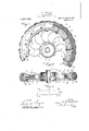
Reference will now be ing, wherein Figure" 1 partly broken away Fig. 2 is a. c w p Fig. 3' is a p an of a detached spring, Fig. 4
had to the draw- '5 a side elevation of a wheel and partly in section,
is a perspective view of the hub partlybroken away andpartly in section, Figs. 5
. and 6 are perspective views of portlons of tire-holding members, Fig. 7 is 'a perspective view of .a. porti on of the felly,
a perspective view of a'portion of the tire. A wheel in accordance with this invention comprises a'metallimhub 1 having a peripheral web 2 intermediate the ends thereof that supports a sleeve 3 arranged circumferen} members, said tire having a I dove-tailed dent-ally displaced, and any suitable antimanently held between the flanges .4 of the ss-sectional view of the same,
and Fig. 8 istially of thehub 1, said sleeve being of a less width than the length of the hub and having the ends thereof provided with peripheral flanges L Ri'veted or otherwlse connected, as at 5 to the sleeve 3 are the inner T-shaped ends 6 .of curved springs 7 and the outenT-shaped, ends of said spring are mounted upon the ends of bolts 8 radially disposed in a felly 9, The outer ends of the spin thave side flanges 1Q engaging the sides of he felly and said bolts are arranged in engagement with the telly by nuts 11. The bolts holda tire member 12 upon the felly 9' and associatedv with said members is another tire member 13 I that is detachable. The detachable member" 13 is retained in engagement with the fellyf by a plurality of bolts 14 and nuts 15 sc'rewed upon said bolts, the bolts 1 1 being arranged I intermediate the bolts 8,in order not to pair the strength or rigidityof the-telly.- I The members12 and. 13 constitute a holder" for-a tire 16 which is 'cla mpedbetweenjfsaid- I tongue 17 held by the'edges of-the members ofthetire 16 has ribs to prevent the/tire.
from-skidding or slipping on smooth and}; 5
wet surfaces.
e The concave tongue permits of the tire being compressed to a degree which tends to bind the tongue 17 against the confronting" beveled sides of the members 12 and 13. It
is impossible for the tire to become .acciskidding device can be used in connection I with the tire.
With the inner ends of the springs persleeve 3 and the outer ends of the springs engaging the sides of. the felly, the springs cannot become laterally displaced and the hub' is yield'ably held with all of the springs cooperating in supportingthe hub normally concentric of the wheel. I While in the drawing there is illustrated a preferred embodiment of the inventiomit is to be understjood1tha't the. structural, eler ments are susceptible to-such variations and modifications as fall. within the: scopesof the appendedv cleim.
A vehicle wheel comprising 'a hub prcr-v vided with a peripheral web, a peripherally 1 flanged sleeve integral with the web, curved 9 a? The tongue 17 is concave ,and' the periphery springs having T-shaped ends, the inner springs to the felly, and a tire carried by the ends of said springs abutting against the felly. 10 flanges of said sleeve, means for fixedly se- In testimony whereof I aflix my signature curing the inner ends of the springs to said in the presence of two Witnesses.
' sleeve, a felly, the outer ends of said GEORGE D. BULMER.
springs abutting against the felly and fur- Witnesses: ther bent to engage the sides of the telly, I THos. V. JoNEs, means'for securing the outer ends of said 1 WM. L. EVANS.
Priority Applications (1)
| Application Number | Priority Date | Filing Date | Title |
|---|---|---|---|
| US72673412A US1059026A (en) | 1912-10-19 | 1912-10-19 | Vehicle-wheel. |
Applications Claiming Priority (1)
| Application Number | Priority Date | Filing Date | Title |
|---|---|---|---|
| US72673412A US1059026A (en) | 1912-10-19 | 1912-10-19 | Vehicle-wheel. |
Publications (1)
| Publication Number | Publication Date |
|---|---|
| US1059026A true US1059026A (en) | 1913-04-15 |
Family
ID=3127279
Family Applications (1)
| Application Number | Title | Priority Date | Filing Date |
|---|---|---|---|
| US72673412A Expired - Lifetime US1059026A (en) | 1912-10-19 | 1912-10-19 | Vehicle-wheel. |
Country Status (1)
| Country | Link |
|---|---|
| US (1) | US1059026A (en) |
Cited By (1)
| Publication number | Priority date | Publication date | Assignee | Title |
|---|---|---|---|---|
| US2869608A (en) * | 1955-11-09 | 1959-01-20 | Palm Roy Inc | Spring wheel |
-
1912
- 1912-10-19 US US72673412A patent/US1059026A/en not_active Expired - Lifetime
Cited By (1)
| Publication number | Priority date | Publication date | Assignee | Title |
|---|---|---|---|---|
| US2869608A (en) * | 1955-11-09 | 1959-01-20 | Palm Roy Inc | Spring wheel |
Similar Documents
| Publication | Publication Date | Title |
|---|---|---|
| US1178887A (en) | Spring-wheel. | |
| US1466133A (en) | Resilient tire | |
| US2505680A (en) | Pneumatic sanding wheel | |
| US1469020A (en) | Resilient channel and cushion tire | |
| US1077799A (en) | Vehicle-wheel. | |
| US801632A (en) | Vehicle-wheel. | |
| US1501583A (en) | Spring wheel | |
| US965443A (en) | Emergency-tire. | |
| US1015888A (en) | Vehicle-wheel. | |
| US1075637A (en) | Spring vehicle-wheel. | |
| US1180671A (en) | Vehicle-tire. | |
| US1588480A (en) | Resilient wheel | |
| US804891A (en) | Vehicle-tire. | |
| US1132462A (en) | Vehicle-wheel. | |
| US1408832A (en) | Pneumatic-tire protector | |
| US1244265A (en) | Spring-wheel. | |
| US1570359A (en) | Antiskid attachment for automobile wheels | |
| US1135290A (en) | Vehicle-wheel. | |
| US1021711A (en) | Vehicle wheel-tire. | |
| US1320401A (en) | Attachment toe | |
| US677867A (en) | Vehicle-tire. | |
| US1083886A (en) | Shoe attachment for automobile-wheels. | |
| US1413159A (en) | darche | |
| US1036599A (en) | Vehicle-wheel. | |
| US654027A (en) | Pneumatic wheel. |