US1058974A - Friction-clutch pulley. - Google Patents
Friction-clutch pulley. Download PDFInfo
- Publication number
- US1058974A US1058974A US70964712A US1912709647A US1058974A US 1058974 A US1058974 A US 1058974A US 70964712 A US70964712 A US 70964712A US 1912709647 A US1912709647 A US 1912709647A US 1058974 A US1058974 A US 1058974A
- Authority
- US
- United States
- Prior art keywords
- shoes
- sleeve
- levers
- clutch
- friction
- Prior art date
- Legal status (The legal status is an assumption and is not a legal conclusion. Google has not performed a legal analysis and makes no representation as to the accuracy of the status listed.)
- Expired - Lifetime
Links
- 241000239290 Araneae Species 0.000 description 8
- 238000010276 construction Methods 0.000 description 2
- 230000000694 effects Effects 0.000 description 2
- 210000005069 ears Anatomy 0.000 description 1
Images
Classifications
-
- F—MECHANICAL ENGINEERING; LIGHTING; HEATING; WEAPONS; BLASTING
- F16—ENGINEERING ELEMENTS AND UNITS; GENERAL MEASURES FOR PRODUCING AND MAINTAINING EFFECTIVE FUNCTIONING OF MACHINES OR INSTALLATIONS; THERMAL INSULATION IN GENERAL
- F16D—COUPLINGS FOR TRANSMITTING ROTATION; CLUTCHES; BRAKES
- F16D13/00—Friction clutches
- F16D13/14—Friction clutches with outwardly-movable clutching members co-operating with the inner surface of a drum or the like
- F16D13/16—Friction clutches with outwardly-movable clutching members co-operating with the inner surface of a drum or the like shaped as radially-movable segments
Definitions
- This invention relates to friction clutches of the type in which the drivin member radially moving shoes or devices that are forced into and out of engagement with the driven member of the clutch.
- the main object of my invention is to provide a clutch of the type mentioned which is so designed that all of the gripplng shoes on the driving member can be adjusted simultaneously, thus insuring an accurate adjustment of the cooperatingfriction surfaces of the clutch and preventing a greater degree of frictional engagement at one point than at another.
- Another object is to provide a friction clutch of novel design which is so constructed that the gripping shoes on the driving member will not drag on the driven member when the clutch is thrown out. And still another object is to provide a strong and serviceable clutch of simple design that can be manufactured at-a low cost.
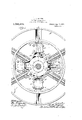
- Figure l of the drawings is a front elevational view of a clutch constructed in accordance with my invent-ion; and .
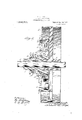
- Fig. 2 is a longitudinal sectional View of the clutch.
- A designates the spider of the driving member of the clutch which is provided with a hub '1'" which is securely connected to the driving shaft 2 in any suitable manner
- B designates the driven member of the clutch herein shown as a pulley provided with a symmetrical hub 3 that is loosely mounted on the driv ng shaft 2.
- the driving member is provided with a plurality of gripping shoes or devioes 4 that are moved radially into and out of engagement with a laterally projecting annular flange or friction ring 5 on one side f the driven member B, sa1d gripping shoes 4 consists ment with the gripping shoes being moved outwardly'into engagement with the flange 5 by a manuallyoperated means under control of the operator, and in the opposite direction out of engagement with said flange by said manually-operated means or by springs or other suit-able resilient devices in case said manually-operated means fails to withdraw the gripping shoes from said flange.
- the grippingv shoes 4 are slidingly mounted in housings or guideways 6 on the spider A of the driven member, each of said housings comprising a detachablecover or capplate 6.
- Each of the links 9 is pivotally connected at 9 to the outer end portion of the gripping shoe with which it coiiperates, and said shoe is provided with an elongated slot, as shown in Fig, 2, so as to provide a clearance for the link 9 and thus permit it to swing on the pivot pin 9 11s a fulcrum when thesleeve 7 is moved longit-udinally of the hub 1 on which it is slidingly mounted.
- the sleeve 7 is moved to the right, looking at Fig. 2.
- a manually-operated device that cooperates with acollar 10, on the sleeve 9, and said sleeve is moved in the opposite direction or to the left so as to withdraw the gripping shoes 4 from enga eflange 5 by said manual.
- yoperated device or by means of coiled expansion springs 11 which. are seated in pockets formed in the spider A of the driving member.
- Means is provided for guiding and limiting the outward movement of the 5 on the driven sleeve 7, namely, the movement of said sleeve in the direction to Withdraw the gripping shoes from engagement with the driven member of the clutch, and in the preferred form of my invention as herein shown, said means consists of guides or studs 1.2 on the spider A that project laterally through openings inears 13 on the sleeve '7 and which are provided with nuts or other suit able adjustable devices'le that cooperate with the ears 13 to limit the outward movement of the sleeve 7.
- the clutch in such a manner that'all of the gripping shoes will be ,adjusted simultaneousl and the same degree when it is desired to c ange I the adjustment of the clutch.
- I accomplish this by providing the driving member with an adjustable part that bears a ainst the levers 8 forming part-of the togg e connections between the gripping shoes 4 and the sleeve 7 so'as to vary the position of said levers;
- the adjustable part of the clutch herein shown consists of the collar 10 previously mentioned which is provided; with internal, screw-threads that cooperate with external screw-threads on the sleeve 7 thereby enabling said collar to be adjusted l ngitudinally of the sleeve 7 so as to move the levers 8 on their fulcrum and thus change the position of the gripping shoes 4 with relation to the sleeve 7.
- Stop screws 15 are adjustably mounted in the outer ends of the levers 8 so as to limit the movement of said levers in one direction and thus cause them to remainstationary with respecttotthe sleeve 7 after the ad usting col lar' lOfQ'has been moved into engagement with the outer ends of the levers 8, as
- a washer 16 may be arranged between the adjusting collar 10 and the outer ends of the levers 8, and means may be provided for locking the collar 10 in adjusted position, the means herein shown consisting of one or more set screws 17 mounted in said collar and adapt- .ed to engage the outer end of the sleeve 7, as shown in Fig. 2.
- the stop screws 15 out.
- the spider A of the driving member of the clutch is provided with laterally projecting flanges 18 that merge into the side walls of said housings and thus rigidly connect all of the housings together, as shown clearly in Fig. 1.
- a friction clutch comprising a driving member provided with a cylindrical-shaped hub, a driven member, gripping shoes car-- ried by one of said members for coiiperating with the other member, a reciprocating actuatin element slidingly mounted on the hub of t e member which carries said gripping shoes, toggle levers pivotally mounted on said hub and pivot ly connected by means of links to said shoes, and an adj usting device on said actuating element that cooperates with said toggle levers so as to eflect the adjustment of all of said gripping shoes simultaneously.
- a friction clutch pulley comprising a driving member provided with closed guideways, a driven member, radially moving shoes slidingly mounted in the guideways in said driving member, a cylindrical hub on said driving member, a movable actuating" element reciprocatingly mounted on said hub, toggles comprising levers pivotally mounted on said hub and links that connect said levers to said gripping shoes, an adjusting device on said actuating element that cooperates with said toggle levers to move same in one direction and thus efl'ect a simultaneous adjustme t of all of the gripping shoes, and adjus ble stops in said levers that bear against said actuating element and thus determine the degree of movement which said adjusting device imparts to said levers.
- a friction clutch pulley comprising a driving member, a driven member, radially moving shoes slidingly mounted in. said driving member, an actuating sleeve slidingly mounted on a hub on said driving member, toggle levers pivotally connected to said sleeve, links that join said levers to said gripping shoes, a rotatable collar mounted on said sleeve and arranged to engage said to gle levers and move them so as to move al of the levers simultaneously I saidtoggle levers simultaneous] oosen with res set to said sleeveand thus vary the position of said gripping shoes, adjustable means for determining the degree of adjustment of said toggle levers by said collar and for holding said levers stationary with respect to said sleeve, and resilient means for actuating said sleeve so as to withdraw said gripping shoes from ongagement with the driven member.
- a friction clutch pulley comprising a driving member, a driven member, radially moving shoes on said driving member for cooperating with said driven member, a mo vable actuating element, toggle levers for connecting said actuating element and gripping shoes together, means for adjusting all of so as to vary the frictional engagement said shoes on the driven member, resilient means interposed between said actuating element and saidadiiving member for. moving said actusting element in a direction to withdraw siiid "gripping shoes from engagement with said driven member, guides on said driving member that pass through said actuating element, and means on said guides for limiting. the movement of said actuating menu-- be when it is acted upon by said resilient means.
- a friction clutch pulley comprising a locsely mounted pulley provided with an annular friction flange
- a driving member having a hub that is securely connected to a driving shaft, radially moving gripping shoes on said drivingv member, a closed housing on said driving member in which said shoes areslidingly mounted, a movable actuating sleeve mounted on the hub of said driving member, toggle levers pivotally mounted on said sleeve, links pivotally connected to said gripping shoes “and to said levers and arranged in slots in said sleeves, and an ZLClJIlStlIlg collar rotatably mounted on said sleeveand arranged to engage said toggle levers so as to effect a simultaneous adjustment of all of the 6.
- a friction clutch loosely mounted annular friction having a hub that gripping shoes.
- a driving member is securely connected to a driving shaft, radially movinggrippin shoes slidiugly mounted in housings in said driving member, a movable actuating sleeve mounted on the hub of said driving member, toggle levers pivotally mounted on said sleeve, links that connect said levers to said gripping shoes, an adjusting collar mounted loosely mounted on a driving shaft, a ringsha ed flange rojecting laterally from said 111 ey, a spi er arranged inside of said ange and having a hub that is rigidly connected to said driving shaft, radially moving gripping shoes slidingly mounted in guideways in said spider, removable mom-- udeways for re-' bers forming art of said taining said s oes in position,'an actuatin sleeve slidingly mounted on the hub of sai spider, toggle levers pivotally connected to said s
Landscapes
- Engineering & Computer Science (AREA)
- General Engineering & Computer Science (AREA)
- Mechanical Engineering (AREA)
- Footwear And Its Accessory, Manufacturing Method And Apparatuses (AREA)
Description
A. HOLZER. FRICTION CLUTCH PULLEY.
' APPLIGATION FILED JULY 16, 191 2.
2 SHEET$-SHEET l.
v ,Zkwz;
Patented Apr: 15, 1913.
H HOLZER.
FRICTION CLUTCH PULLEY.
APPLICATION TILED JULY 16, 1912.
Patented Apr. 15, 1913.
2 SHEETS-@HEET 2.
. [rave/6%];
is provided with a plurality o UNITED snares HIRAM A. HOLZER, OF PITTSBURG', KANSAS,
IANY, 0F SPRINGFIELD, MISSOURI, A
OFFICE.
ASSIGNOR T0 UNITED IROiN WORKS COIL.
CORPORATION OF MISSOURI.
FRICTION-CLUTCH PULLEY.
Specification of Letters Patent.
Application filed July 16, 1912. Serial N 0. 709,647. i
To all whom it may concern:
Be it known that ,I 'HlRAMI A. Honzun, a citizen of the United States, residing at Pittsburg, Kansas, have invented a certain new and useful Impgovement in Friction- Cluteh Pulleys, of which the following is a full, clear, and exact description, such as.
will enable others skilled in the art to which it appertains to make and use the same.
This invention relates to friction clutches of the type in which the drivin member radially moving shoes or devices that are forced into and out of engagement with the driven member of the clutch.
The main object of my invention is to provide a clutch of the type mentioned which is so designed that all of the gripplng shoes on the driving member can be adjusted simultaneously, thus insuring an accurate adjustment of the cooperatingfriction surfaces of the clutch and preventing a greater degree of frictional engagement at one point than at another.
Another object is to provide a friction clutch of novel design which is so constructed that the gripping shoes on the driving member will not drag on the driven member when the clutch is thrown out. And still another object is to provide a strong and serviceable clutch of simple design that can be manufactured at-a low cost.
Other objects and desirablefeatures of my invention will be hereinafter pointed out. c
Figure l of the drawings is a front elevational view of a clutch constructed in accordance with my invent-ion; and .Fig. 2 is a longitudinal sectional View of the clutch.
Referring to the drawings which illustrate the preferred form of my invention, A designates the spider of the driving member of the clutch which is provided with a hub '1'" which is securely connected to the driving shaft 2 in any suitable manner, and B designates the driven member of the clutch herein shown as a pulley provided with a symmetrical hub 3 that is loosely mounted on the driv ng shaft 2. The driving member is provided with a plurality of gripping shoes or devioes 4 that are moved radially into and out of engagement with a laterally projecting annular flange or friction ring 5 on one side f the driven member B, sa1d gripping shoes 4 consists ment with the gripping shoes being moved outwardly'into engagement with the flange 5 by a manuallyoperated means under control of the operator, and in the opposite direction out of engagement with said flange by said manually-operated means or by springs or other suit-able resilient devices in case said manually-operated means fails to withdraw the gripping shoes from said flange. The grippingv shoes 4 are slidingly mounted in housings or guideways 6 on the spider A of the driven member, each of said housings comprising a detachablecover or capplate 6. The means herein shown for actuating the of a sleeve 7 slidingly mounted on the huh I of the spider A of the driving member, adjustabletoggle levers 8 carried by the sleeve 7, and toggle links 9 pivotally connected tothe inner ends of the levers 8 and to the gripping shoes 4, a'lever 8 and link 9 being 'PI'OVldGd for each gripping shoe 4. Each of the links 9 is pivotally connected at 9 to the outer end portion of the gripping shoe with which it coiiperates, and said shoe is provided with an elongated slot, as shown in Fig, 2, so as to provide a clearance for the link 9 and thus permit it to swing on the pivot pin 9 11s a fulcrum when thesleeve 7 is moved longit-udinally of the hub 1 on which it is slidingly mounted. The sleeve 7 is moved to the right, looking at Fig. 2. so-as to force the gripping shoes 4 outwardly into engagement with the friction flange member by a manually-operated device, not shown, that cooperates with acollar 10, on the sleeve 9, and said sleeve is moved in the opposite direction or to the left so as to withdraw the gripping shoes 4 from enga eflange 5 by said manual. yoperated device, or by means of coiled expansion springs 11 which. are seated in pockets formed in the spider A of the driving member. Means is provided for guiding and limiting the outward movement of the 5 on the driven sleeve 7, namely, the movement of said sleeve in the direction to Withdraw the gripping shoes from engagement with the driven member of the clutch, and in the preferred form of my invention as herein shown, said means consists of guides or studs 1.2 on the spider A that project laterally through openings inears 13 on the sleeve '7 and which are provided with nuts or other suit able adjustable devices'le that cooperate with the ears 13 to limit the outward movement of the sleeve 7.
In order to adjust the rip ing shoes 4 accurately I have designed the clutch in such a manner that'all of the gripping shoes will be ,adjusted simultaneousl and the same degree when it is desired to c ange I the adjustment of the clutch. I accomplish this by providing the driving member with an adjustable part that bears a ainst the levers 8 forming part-of the togg e connections between the gripping shoes 4 and the sleeve 7 so'as to vary the position of said levers; The adjustable part of the clutch herein shown consists of the collar 10 previously mentioned which is provided; with internal, screw-threads that cooperate with external screw-threads on the sleeve 7 thereby enabling said collar to be adjusted l ngitudinally of the sleeve 7 so as to move the levers 8 on their fulcrum and thus change the position of the gripping shoes 4 with relation to the sleeve 7. Stop screws 15 are adjustably mounted in the outer ends of the levers 8 so as to limit the movement of said levers in one direction and thus cause them to remainstationary with respecttotthe sleeve 7 after the ad usting col lar' lOfQ'has been moved into engagement with the outer ends of the levers 8, as
shown "in Fig. 2. If desired, a washer 16 may be arranged between the adjusting collar 10 and the outer ends of the levers 8, and means may be provided for locking the collar 10 in adjusted position, the means herein shown consisting of one or more set screws 17 mounted in said collar and adapt- .ed to engage the outer end of the sleeve 7, as shown in Fig. 2. The stop screws 15 out. In order to reinforce and strengthen the housings 6 on which the gripping shoes 4 are slidingly mounted, the spider A of the driving member of the clutch is provided with laterally projecting flanges 18 that merge into the side walls of said housings and thus rigidly connect all of the housings together, as shown clearly in Fig. 1.
One desirable feature of a friction clutch pulley of the construction above-described 'is that all of the gripping shoes bear with equal pressure on the riction flange of the drivenmember owing to the fact that said shoes move in unison or simultaneously when the collar 10 is adusted. And another desirable feature ofsuc a pulley is that all of the gripping shoes can be adjusted quickly and accurately by manipulating only one part, namely, the collar 10. There is no liability of the ripping shoes drag-- ging on the friction flange of the driven member when the clutch is thrown out because the springs 11 are of sufficient tension to force the sleeve 7 outwardly as soon as the operator throws or releases the actuating device, not shown, that shifts said sleeve and the stop screws 15 in the toggle levers 8 prevent said levers from remaining at rest when the sleeve '7 moves outwardly.
vIn addition to the above desirable fea tures my improved clutch pulley is strong and serviceable, it comprises only a few parts of simple construction that are not apt to get out of order, and it can be manufactured cheaply.
Having thus described my invention, what I claim as new and desire to secure by Letters Patent is:
1. A friction clutch comprising a driving member provided with a cylindrical-shaped hub, a driven member, gripping shoes car-- ried by one of said members for coiiperating with the other member, a reciprocating actuatin element slidingly mounted on the hub of t e member which carries said gripping shoes, toggle levers pivotally mounted on said hub and pivot ly connected by means of links to said shoes, and an adj usting device on said actuating element that cooperates with said toggle levers so as to eflect the adjustment of all of said gripping shoes simultaneously.
2. A friction clutch pulley comprising a driving member provided with closed guideways, a driven member, radially moving shoes slidingly mounted in the guideways in said driving member, a cylindrical hub on said driving member, a movable actuating" element reciprocatingly mounted on said hub, toggles comprising levers pivotally mounted on said hub and links that connect said levers to said gripping shoes, an adjusting device on said actuating element that cooperates with said toggle levers to move same in one direction and thus efl'ect a simultaneous adjustme t of all of the gripping shoes, and adjus ble stops in said levers that bear against said actuating element and thus determine the degree of movement which said adjusting device imparts to said levers.
3. A friction clutch pulley comprising a driving member, a driven member, radially moving shoes slidingly mounted in. said driving member, an actuating sleeve slidingly mounted on a hub on said driving member, toggle levers pivotally connected to said sleeve, links that join said levers to said gripping shoes, a rotatable collar mounted on said sleeve and arranged to engage said to gle levers and move them so as to move al of the levers simultaneously I saidtoggle levers simultaneous] oosen with res set to said sleeveand thus vary the position of said gripping shoes, adjustable means for determining the degree of adjustment of said toggle levers by said collar and for holding said levers stationary with respect to said sleeve, and resilient means for actuating said sleeve so as to withdraw said gripping shoes from ongagement with the driven member.
4.. A friction clutch pulley comprising a driving member, a driven member, radially moving shoes on said driving member for cooperating with said driven member, a mo vable actuating element, toggle levers for connecting said actuating element and gripping shoes together, means for adjusting all of so as to vary the frictional engagement said shoes on the driven member, resilient means interposed between said actuating element and saidadiiving member for. moving said actusting element in a direction to withdraw siiid "gripping shoes from engagement with said driven member, guides on said driving member that pass through said actuating element, and means on said guides for limiting. the movement of said actuating menu-- be when it is acted upon by said resilient means.
5. A friction clutch pulley comprising a locsely mounted pulley provided with an annular friction flange,
a driving member having a hub that is securely connected to a driving shaft, radially moving gripping shoes on said drivingv member, a closed housing on said driving member in which said shoes areslidingly mounted, a movable actuating sleeve mounted on the hub of said driving member, toggle levers pivotally mounted on said sleeve, links pivotally connected to said gripping shoes "and to said levers and arranged in slots in said sleeves, and an ZLClJIlStlIlg collar rotatably mounted on said sleeveand arranged to engage said toggle levers so as to effect a simultaneous adjustment of all of the 6. A friction clutch loosely mounted annular friction having a hub that gripping shoes.
pulley comprising a ulley provided With an ange, a driving member is securely connected to a driving shaft, radially movinggrippin shoes slidiugly mounted in housings in said driving member, a movable actuating sleeve mounted on the hub of said driving member, toggle levers pivotally mounted on said sleeve, links that connect said levers to said gripping shoes, an adjusting collar mounted loosely mounted on a driving shaft, a ringsha ed flange rojecting laterally from said 111 ey, a spi er arranged inside of said ange and having a hub that is rigidly connected to said driving shaft, radially moving gripping shoes slidingly mounted in guideways in said spider, removable mom-- udeways for re-' bers forming art of said taining said s oes in position,'an actuatin sleeve slidingly mounted on the hub of sai spider, toggle levers pivotally connected to said sleeve and provided with adjustable stops that strike against the sleeve, links pivotally connected to the inner ends of said levers and to said gripping shoes, and an adjustable member on said sleeve that cooperates with said togglelevers to effect the simultaneous adjustment of all of said ip ing shoes, and means for locking sai adustable member in the position to which it has been moved.
In testimony whereof I hereunto afiix my signature in the presence of two witnesses, this 9th day of July, 1912.
HIRAM A. HOLZER.
Witnesses:
ORA FRITZ, Gno, H, S'ruEssI.
or looking said collar j,
70 pulley having a symmetrical hub that is
Priority Applications (1)
| Application Number | Priority Date | Filing Date | Title |
|---|---|---|---|
| US70964712A US1058974A (en) | 1912-07-16 | 1912-07-16 | Friction-clutch pulley. |
Applications Claiming Priority (1)
| Application Number | Priority Date | Filing Date | Title |
|---|---|---|---|
| US70964712A US1058974A (en) | 1912-07-16 | 1912-07-16 | Friction-clutch pulley. |
Publications (1)
| Publication Number | Publication Date |
|---|---|
| US1058974A true US1058974A (en) | 1913-04-15 |
Family
ID=3127227
Family Applications (1)
| Application Number | Title | Priority Date | Filing Date |
|---|---|---|---|
| US70964712A Expired - Lifetime US1058974A (en) | 1912-07-16 | 1912-07-16 | Friction-clutch pulley. |
Country Status (1)
| Country | Link |
|---|---|
| US (1) | US1058974A (en) |
-
1912
- 1912-07-16 US US70964712A patent/US1058974A/en not_active Expired - Lifetime
Similar Documents
| Publication | Publication Date | Title |
|---|---|---|
| US1851146A (en) | Automatic clutch | |
| US2073146A (en) | Clutch | |
| US2064450A (en) | Clutch | |
| US157660A (en) | Improvement in friction-clutches | |
| US1571015A (en) | Friction clutch for motor vehicles | |
| US2277273A (en) | Friction clutch | |
| US2384405A (en) | Friction clutch | |
| US788726A (en) | Friction-clutch. | |
| US2251862A (en) | Friction clutch | |
| US837632A (en) | Clutch. | |
| US1167117A (en) | Friction-clutch. | |
| US572957A (en) | Friction-clutch | |
| US970459A (en) | Friction-clutch. | |
| US827475A (en) | Clutch. | |
| US533602A (en) | Clutch | |
| US969577A (en) | Frictional clutch or coupling. | |
| US520528A (en) | jones | |
| US161119A (en) | Improvement in friction-clutch pulleys | |
| US519899A (en) | Clutch | |
| US687459A (en) | Friction-clutch. | |
| US1293053A (en) | Clutch mechanism. | |
| US2321565A (en) | Clutch | |
| US413490A (en) | Clutch | |
| US1064242A (en) | Friction-clutch. | |
| US651842A (en) | Friction-clutch. |