US10589366B2 - Table saw insert with lock-down mechanism - Google Patents
Table saw insert with lock-down mechanism Download PDFInfo
- Publication number
- US10589366B2 US10589366B2 US12/931,809 US93180911A US10589366B2 US 10589366 B2 US10589366 B2 US 10589366B2 US 93180911 A US93180911 A US 93180911A US 10589366 B2 US10589366 B2 US 10589366B2
- Authority
- US
- United States
- Prior art keywords
- insert
- lever
- lock
- axis
- table saw
- Prior art date
- Legal status (The legal status is an assumption and is not a legal conclusion. Google has not performed a legal analysis and makes no representation as to the accuracy of the status listed.)
- Active, expires
Links
- KJLPSBMDOIVXSN-UHFFFAOYSA-N 4-[4-[2-[4-(3,4-dicarboxyphenoxy)phenyl]propan-2-yl]phenoxy]phthalic acid Chemical compound C=1C=C(OC=2C=C(C(C(O)=O)=CC=2)C(O)=O)C=CC=1C(C)(C)C(C=C1)=CC=C1OC1=CC=C(C(O)=O)C(C(O)=O)=C1 KJLPSBMDOIVXSN-UHFFFAOYSA-N 0.000 title claims description 30
- 230000007246 mechanism Effects 0.000 title abstract description 21
- 238000009434 installation Methods 0.000 abstract description 2
- 230000003993 interaction Effects 0.000 description 5
- 239000002184 metal Substances 0.000 description 5
- 238000009987 spinning Methods 0.000 description 5
- 239000000463 material Substances 0.000 description 3
- 238000000034 method Methods 0.000 description 2
- 239000004033 plastic Substances 0.000 description 2
- 230000008569 process Effects 0.000 description 2
- 230000000630 rising effect Effects 0.000 description 2
- 239000002023 wood Substances 0.000 description 2
- 229910000831 Steel Inorganic materials 0.000 description 1
- 230000008901 benefit Effects 0.000 description 1
- 230000008859 change Effects 0.000 description 1
- 238000010348 incorporation Methods 0.000 description 1
- 238000012423 maintenance Methods 0.000 description 1
- ISWSIDIOOBJBQZ-UHFFFAOYSA-N phenol group Chemical group C1(=CC=CC=C1)O ISWSIDIOOBJBQZ-UHFFFAOYSA-N 0.000 description 1
- 230000000284 resting effect Effects 0.000 description 1
- 239000010959 steel Substances 0.000 description 1
Images


Classifications
-
- B—PERFORMING OPERATIONS; TRANSPORTING
- B23—MACHINE TOOLS; METAL-WORKING NOT OTHERWISE PROVIDED FOR
- B23D—PLANING; SLOTTING; SHEARING; BROACHING; SAWING; FILING; SCRAPING; LIKE OPERATIONS FOR WORKING METAL BY REMOVING MATERIAL, NOT OTHERWISE PROVIDED FOR
- B23D47/00—Sawing machines or sawing devices working with circular saw blades, characterised only by constructional features of particular parts
- B23D47/02—Sawing machines or sawing devices working with circular saw blades, characterised only by constructional features of particular parts of frames; of guiding arrangements for work-table or saw-carrier
- B23D47/025—Sawing machines or sawing devices working with circular saw blades, characterised only by constructional features of particular parts of frames; of guiding arrangements for work-table or saw-carrier of tables
-
- B—PERFORMING OPERATIONS; TRANSPORTING
- B23—MACHINE TOOLS; METAL-WORKING NOT OTHERWISE PROVIDED FOR
- B23D—PLANING; SLOTTING; SHEARING; BROACHING; SAWING; FILING; SCRAPING; LIKE OPERATIONS FOR WORKING METAL BY REMOVING MATERIAL, NOT OTHERWISE PROVIDED FOR
- B23D45/00—Sawing machines or sawing devices with circular saw blades or with friction saw discs
- B23D45/06—Sawing machines or sawing devices with circular saw blades or with friction saw discs with a circular saw blade arranged underneath a stationary work-table
-
- Y—GENERAL TAGGING OF NEW TECHNOLOGICAL DEVELOPMENTS; GENERAL TAGGING OF CROSS-SECTIONAL TECHNOLOGIES SPANNING OVER SEVERAL SECTIONS OF THE IPC; TECHNICAL SUBJECTS COVERED BY FORMER USPC CROSS-REFERENCE ART COLLECTIONS [XRACs] AND DIGESTS
- Y10—TECHNICAL SUBJECTS COVERED BY FORMER USPC
- Y10T—TECHNICAL SUBJECTS COVERED BY FORMER US CLASSIFICATION
- Y10T83/00—Cutting
- Y10T83/768—Rotatable disc tool pair or tool and carrier
- Y10T83/7684—With means to support work relative to tool[s]
- Y10T83/773—Work-support includes passageway for tool [e.g., slotted table]
Definitions
- the present invention relates to inserts for table saws.
- the insert includes a lock-down mechanism to hold the insert in place.
- a table saw In a workshop environment, such as a wood-working workshop, a table saw is commonly used to cut a workpiece, such as a piece of wood, plastic, metal or the like.
- a table saw is a piece of power equipment that has a flat table to support a workpiece, and a blade extends up through an opening in the table. The workpiece is placed on the table and pushed forward into the spinning blade to make a cut.
- an opening is left in the table, and during use, the opening is filled by a removable table insert.
- the insert has a flat surface to match the surface of the table and a slot through which the blade extends. It is important that the table insert be secured in the saw so that it does not come loose while the blade is spinning, as this would create a hazard.
- Some inserts are designed as “zero-clearance” inserts.
- a zero-clearance insert has a slot that matches as closely as possible the profile or width of the blade.
- a zero-clearance insert is manufactured without a slot for the blade.
- the zero-clearance insert is then installed in a saw with the blade lowered to a position below the table surface.
- the motor is turned on so that the blade spins and the spinning blade is slowly raised so that is cuts through the zero-clearance insert, leaving a slot in the insert that matches as closely as possible the profile of the blade. It is particularly important that the table insert be securely kept in place during this process.
- inserts have been held in place by screws that extend through a hole in the insert and thread into a bore in the table.
- Such a configuration makes it inconvenient for a user to install or remove the insert because a screwdriver would be required. Also, the screw could be lost or a screwdriver might not be readily available.
- This document describes a table insert designed for a table saw which mechanically, and easily, locks in place without the use of tools.
- FIG. 1 shows a table saw
- FIG. 2 shows a table insert with the lever of a locking mechanism pivoted down.
- FIG. 3 shows a table insert with the lever of a locking mechanism pivoted up.
- FIG. 4 shows a view of the table of the saw with some of the table and insert removed.
- FIG. 5 shows a cross-sectional view of FIG. 4 .
- FIG. 6 shows a view of the table of the saw with some of the table removed.
- FIG. 7 shows a cross-sectional view of FIG. 6 .
- FIG. 8 shows the lever of a locking mechanism isolated.
- FIG. 9 shows a side view of the locking mechanism lever of FIG. 8 .
- FIG. 10 shows a rear view of the locking mechanism lever of FIG. 8 .
- FIG. 11 shows a top view of the locking mechanism lever of FIG. 8 .
- FIG. 12 shows and alternative embodiment of a lever.
- FIG. 13 shows a side view of the alternative lever of FIG. 12 .
- FIG. 14 shows a zero-clearance insert without a slot for a blade.
- FIG. 15 shows a zero-clearance insert with a slot for a blade.
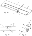
- FIG. 16 shows, in cross-section, a lock-down mechanism using a T-shaped bolt.
- FIG. 17 shows a cross-sectional view of the T-shaped bolt in use.
- FIG. 18 shows the T-shaped bolt in a locked position.
- FIG. 19 shows, in cross-section, a lock-down mechanism using a tab.
- FIG. 20 shows a cross-sectional view of the tab of FIG. 19 in use.
- FIG. 21 shows the tab of FIG. 19 isolated from other structure.
- FIG. 22 shows a lock-down mechanism using a latch.
- FIG. 1 A table saw 10 is shown in FIG. 1 .
- Saw 10 includes a table 12 and a circular blade 14 .
- the blade extends up through a slot 16 in a table insert 18 .
- the insert fits within an opening 20 in the table and the top surface of the insert is nominally co-planar with the top surface of the table.
- a piece of wood, or other material to be cut, is placed on the table and pushed into contact with the spinning blade to make a cut.
- a riving knife 22 or similar component such as a splitter, is mounted under the table behind the blade and also extends up through a slot 24 in table insert 18 .
- Both the riving knife (or splitter) and the blade can be moved up and down together by turning hand wheel 26 , and can be tilted from zero to forty-five degrees to the left by turning hand wheel 28 . Slots 16 and 24 in the table insert accommodate this movement.
- table insert 18 covers opening 20 in table 12 of the saw.
- Opening 20 is an oblong opening with straight sides and semi-circles at each end. Opening 20 surrounds the blade and riving knife and is large enough to allow access to the internal saw assembly so that the operator of the saw can change the blade, install or remove the riving knife, or perform other maintenance tasks.
- Table insert 18 is shaped to closely fit within opening 20 and is designed to sit flush or nearly flush with the table surface so that a workpiece may glide smoothly over the table insert without interference.
- FIGS. 2 and 3 show table insert 18 isolated from the saw.
- the main body 30 of the table insert 18 may be made of a rigid material that resists warping, such as phenolic, or it may be made of plastic that is reinforced by an inner plate of steel or some other metal.
- Two front leveling screws 32 and two rear leveling screws 34 are installed in the table insert.
- the ends of the leveling screws adjacent the top of the insert have a molded hexagonal inset in which the end of a hex wrench can be inserted to turn the screw.
- the opposite or lower ends of the front and rear leveling screws contact ledges 36 and 38 , respectively, that extend underneath the table insert from the underside of table 12 , as shown in FIGS. 5 and 7 .
- the screws allow the operator of the saw to adjust the height of the table insert so that the surface of the table insert is flush, or nearly flush, with the surface of table 12 .
- Two positioning set screws 40 one along the middle of the right side of the table insert and one towards the middle of the rear side of the table insert, allow the table insert to be adjusted so that it fits snuggly side-to-side within opening 20 .
- Two generally rectangular metal plates 42 one along either side of opening 24 in the table insert, provide hard contact surfaces for the sharp tips of anti-kickback pawls that are typically mounted to a splitter incorporated in a blade guard.
- a small cutout 44 in the left plate helps prevent an anti-kickback pawl from catching on the rear leveling screw.
- each rear leveling screw 34 The bottom end of each rear leveling screw includes a head that overlaps the heads of screws threaded into tabs 38 on table 12 , as shown in FIG. 7 .
- the overlap locks down the rear of the insert and prevents the rear of the insert from rising up.
- the front end is held higher than the back end so that the table insert is at a slight angle. This allows the heads of the rear leveling screws to slide under, or out from under, the heads of screws that are mounted in the table on ledges 38 .
- lever 46 The front of table insert 18 is held securely in place within opening 20 by a mechanical locking mechanism that consists of a lever 46 that works in conjunction with ledges 36 formed on the underside of table 12 .
- lever 46 has a handle 48 made of a narrow strip of metal bent to form a semi-circular shape that matches the front end of insert 18 .
- some material from the main body 30 of the table insert is removed at the front end so there is room for lever 46 to fit along the outside of the main body.
- FIGS. 8-11 show various views of lever 46 isolated.
- There is a hole 52 shown in FIG. 8 , at each end of handle 48 , and a screw 54 passes through each hole to attach each end of lever 46 to the right and left side of the insert 18 in such a way to allow the lever to pivot upward about those screws, as shown in FIG. 3 .
- a lift tab 56 is formed at the front of lever 46 by a small, semicircular shaped extension along the top edge of the lever, at the middle of the lever. The extension or tab is bent inward so that it is at a right angle to the front side of the lever.
- Table insert 18 has a recessed area 58 below lift tab 56 that is shaped so that tab 56 is substantially flush with the table top when the lever is down as shown in FIG. 2 .
- the recessed area is also large enough to allow the operator of the saw to place a finger underneath the lift tab in order to lift lever 46 and pivot it upward.
- a side portion 50 extends down below the table insert, as shown in FIG. 2 .
- a projection bends inward at a right angle to create a tab 60 , as shown in FIGS. 8 and 11 .
- the front edge 62 of each tab 60 is shaped to contact the underside of table insert 18 when lever 46 pivots upward to limit how far the lever can pivot upward, as shown in FIG. 3 .
- each tab 60 extends out to form arms 64 .
- Each arm 64 slopes upward for a length and then curves back down slightly at the end to terminate in contact areas 66 , as shown in FIG. 8 .
- Arms 64 are shaped and sized to fit under ledges 36 in the table when lever 46 is pivoted down to hold the insert in place.
- arms 64 are positioned just below ledges 36 on either side of the table insert when the table insert is fully installed. There may be a small gap between the top of arm 64 and the underside of the ledge. In the case of an upward force on the table insert, contact areas 66 at the top of the curved ends of each arm 64 will contact the underside of ledges 36 .
- Contact areas 66 are positioned directly below the pivot axis of lever 46 (which runs through the center of each screw 54 ), or forward of the pivot axis (forward meaning toward lift tab 56 ) so that an upward force acting on the table insert will not tend to pivot lever 46 up; rather, lever 46 will remain locked in place.
- the contact areas are directly below the pivot axes. If the contact areas were past the pivot axes toward the rear of the insert, an upward force on the table insert would tend to pivot lever 46 up and the table insert could be dislodged.
- Arms 64 are strong enough to resist an upward force on the table insert, but also flexible enough to be bent with a tool in order to fit under thicker or thinner ledges 36 , as the thickness of the ledges may vary between different saw tables.
- An alternative configuration of arms 64 are shown in FIGS. 12 and 13 . In this configuration, arms 64 are not configured to be bent to accommodate ledges 36 of varying thickness.
- FIG. 14 shows a zero-clearance insert with a lock-down lever before the slot is cut for the blade.
- a user would lower the blade and position the insert in the table opening and make sure the insert was locked down by the rear screws and the front lock-down lever.
- the user may also place a board across the top of the insert and clamp the board to the saw table. The user would then start the saw and slowly raise the blade.
- the spinning blade would cut a slot in the insert as the blade rises, and the lock-down lever and rear screws would help hold the insert in place against the upward force of the rising blade.
- a zero-clearance insert with a blade slot is shown in FIG. 15 .
- Lever 46 also acts as a handle when pivoted up, which can be used to facilitate installation or removal of the insert from the saw.
- a user would place a finger under lift tab 56 , pivot lever 46 up to move arms 64 out from under ledges 36 , hold and lift up the lever slightly to cause the front end of the insert to rise, and then slide the insert towards the front of the saw to disengage the overlapping rear screws and remove the insert from the saw. The process is repeated in reverse to install the insert in the saw.
- FIGS. 16-18 show another embodiment of a lock-down mechanism for a table saw insert.
- the mechanism includes a T-shaped bolt 70 that threads into a threaded hole 72 in a ledge 74 that extends under the front of the insert from the underside of table 12 .
- a large circular recess 76 in the top of the insert surrounds a slot 78 at the front of the table insert above hole 72 .
- the table insert When bar 80 is rotated so that it is at a 90 degree angle with slot 78 , the table insert will be locked in place.
- the table insert may be removed by placing a finger through another hole 82 in the insert and lifting the front end up allowing bar 80 to pass through slot 78 .
- FIGS. 19-21 show another lock-down mechanism to secure an insert in place.
- a metal tab 90 is attached to the table under the insert and extends up through an opening 92 in the insert.
- the tab is attached to the table by screw 94 .
- the tab is in a closed position with the shoulders or edges 96 of the wider top portion of the tab resting upon a sunken surface 98 on the insert.
- a user flexes the tab so that the upper portion of the tab is moved off of surface 98 into opening 92 where it clears the table insert. With the tab flexed, a user reaches through opening 82 in the insert to lift and remove the insert.
- FIG. 22 shows another lock-down mechanism to secure an insert in place.
- a latch 100 pivots under the insert to hold the insert in place.
- the latch 100 may be designed to lock the insert in place in many different ways.
- the latch may pivot so that one end of the latch is under table 12 or it may pivot so that a notch in one end of the latch fits under the head of a screw 102 that is threaded into the table.
- latch 100 pivots around screw 104 and a spring 106 biases the latch closed.
- a user reaches through opening 82 in the insert, pivots the latch and lifts up the insert.
- the lock-down structures described herein may be thought of as mechanical lock-down means for holding the insert in place. These lock-down structures hold an insert in place, and prevent the insert from moving up, through a physical abutment of parts or through what may be thought of as an inelastic interaction of parts, while still allowing a user to release the lock-down structure and remove the insert without the use of a screwdriver, wrench or other tool.
- arms on a lever may abut or interact with a ledge, and the lever may be pivoted by hand to release the interaction.
- the top of a T-shaped bolt may abut or interact with a surface on the insert, and the T-shaped bolt can be turned by hand to release the abutment.
- An edge or shoulder on a tab may abut or interact with a surface on an insert, and the tab can be flexed to release the abutment.
- a latch may abut or interact with a screw or some other surface, and a user can pivot the latch to release the interaction.
- These types of interactions may be referred to as positive mechanical interactions or as hand-operable mechanical locks.
- These structures would have to undergo an inelastic deformation for the insert to be removed other than by releasing the lock-down structure. This is in contrast to prior mechanisms used to keep an insert in place, such as spring-biased buttons, spring-biased rollers, or leaf springs designed to flex into and out of a notch.
- spring-biased buttons, spring-biased rollers, or leaf springs designed to flex into and out of a notch are examples of mechanisms do not hold the insert in place against an upward force, such as a user pulling up on the insert to remove the insert, or such as cutting a slot in a zero-clearance insert, and
- the table inserts with toolless lock-down mechanisms disclosed herein are applicable to woodworking power tool equipment, and particularly to table saws.
- the described inserts provide a simple and effective means for securing and removing an insert without the use of tools.
Landscapes
- Engineering & Computer Science (AREA)
- Mechanical Engineering (AREA)
- Sawing (AREA)
Abstract
Description
Claims (10)
Priority Applications (6)
| Application Number | Priority Date | Filing Date | Title |
|---|---|---|---|
| US12/931,809 US10589366B2 (en) | 2010-02-19 | 2011-02-11 | Table saw insert with lock-down mechanism |
| US13/854,270 US20170190012A9 (en) | 1999-10-01 | 2013-04-01 | Power equipment with detection and reaction systems |
| US14/720,552 US20150273725A1 (en) | 1999-10-01 | 2015-05-22 | Table saws with detection and reaction systems |
| US14/721,182 US20150321271A1 (en) | 2010-02-19 | 2015-05-26 | Table saw insert with lock-down mechanism |
| US15/924,797 US11548083B2 (en) | 2010-02-19 | 2018-03-19 | Inserts for table saws |
| US16/819,837 US11273504B2 (en) | 2010-02-19 | 2020-03-16 | Table saw insert with lock-down mechanism |
Applications Claiming Priority (2)
| Application Number | Priority Date | Filing Date | Title |
|---|---|---|---|
| US33849310P | 2010-02-19 | 2010-02-19 | |
| US12/931,809 US10589366B2 (en) | 2010-02-19 | 2011-02-11 | Table saw insert with lock-down mechanism |
Related Parent Applications (1)
| Application Number | Title | Priority Date | Filing Date |
|---|---|---|---|
| US13/385,415 Continuation US10967536B2 (en) | 1999-10-01 | 2012-02-17 | Blade guard for a table saw |
Related Child Applications (5)
| Application Number | Title | Priority Date | Filing Date |
|---|---|---|---|
| US12/214,562 Continuation US8079295B2 (en) | 1999-10-01 | 2008-06-20 | Table saw blade guards and blade guard assemblies including lateral blade guards, and table saws including the same |
| US13/854,270 Continuation US20170190012A9 (en) | 1999-10-01 | 2013-04-01 | Power equipment with detection and reaction systems |
| US14/517,522 Continuation US9919369B2 (en) | 2010-02-19 | 2014-10-17 | Inserts for table saws |
| US14/721,182 Continuation US20150321271A1 (en) | 2010-02-19 | 2015-05-26 | Table saw insert with lock-down mechanism |
| US16/819,837 Continuation US11273504B2 (en) | 2010-02-19 | 2020-03-16 | Table saw insert with lock-down mechanism |
Publications (2)
| Publication Number | Publication Date |
|---|---|
| US20110203438A1 US20110203438A1 (en) | 2011-08-25 |
| US10589366B2 true US10589366B2 (en) | 2020-03-17 |
Family
ID=44475370
Family Applications (3)
| Application Number | Title | Priority Date | Filing Date |
|---|---|---|---|
| US12/931,809 Active 2037-09-04 US10589366B2 (en) | 1999-10-01 | 2011-02-11 | Table saw insert with lock-down mechanism |
| US14/721,182 Abandoned US20150321271A1 (en) | 2010-02-19 | 2015-05-26 | Table saw insert with lock-down mechanism |
| US16/819,837 Active US11273504B2 (en) | 2010-02-19 | 2020-03-16 | Table saw insert with lock-down mechanism |
Family Applications After (2)
| Application Number | Title | Priority Date | Filing Date |
|---|---|---|---|
| US14/721,182 Abandoned US20150321271A1 (en) | 2010-02-19 | 2015-05-26 | Table saw insert with lock-down mechanism |
| US16/819,837 Active US11273504B2 (en) | 2010-02-19 | 2020-03-16 | Table saw insert with lock-down mechanism |
Country Status (1)
| Country | Link |
|---|---|
| US (3) | US10589366B2 (en) |
Families Citing this family (18)
| Publication number | Priority date | Publication date | Assignee | Title |
|---|---|---|---|---|
| US9724840B2 (en) | 1999-10-01 | 2017-08-08 | Sd3, Llc | Safety systems for power equipment |
| US9927796B2 (en) | 2001-05-17 | 2018-03-27 | Sawstop Holding Llc | Band saw with improved safety system |
| US9919369B2 (en) * | 2013-10-17 | 2018-03-20 | Sawstop Holding Llc | Inserts for table saws |
| CN102554343B (en) * | 2012-01-17 | 2014-01-29 | 太仓威格玛机械设备有限公司 | Full-automatic corner connector cutting device |
| EP2969340B1 (en) * | 2013-03-13 | 2021-11-17 | Robert Bosch GmbH | Bevel table saw |
| TWI535521B (en) | 2013-08-15 | 2016-06-01 | Rexon Ind Corp Ltd | Insert for circular saw |
| WO2016040432A1 (en) * | 2014-09-09 | 2016-03-17 | Robert Bosch Gmbh | Table top and throat plate for power table saws |
| US10427227B2 (en) | 2015-03-12 | 2019-10-01 | Robert Bosch Tool Corporation | Drop arm reset method |
| US10799964B2 (en) | 2015-03-12 | 2020-10-13 | Robert Bosch Tool Corporation | Table saw with pulley alignment mechanism |
| US10758989B2 (en) | 2015-03-12 | 2020-09-01 | Robert Bosch Tool Corporation | System and method for sensing cable fault detection in a saw |
| US9687922B2 (en) * | 2015-03-12 | 2017-06-27 | Robert Bosch Tool Corporation | Power tool with cammed throat plate |
| US10821529B2 (en) | 2015-03-12 | 2020-11-03 | Robert Bosch Tool Corporation | Power tool with improved belt tensioning |
| US10493543B2 (en) | 2015-03-12 | 2019-12-03 | Robert Bosch Tool Corporation | Power tool motor with reduced electrical noise |
| US10322522B2 (en) | 2015-03-12 | 2019-06-18 | Robert Bosch Tool Corporation | Electrical configuration for object detection system in a saw |
| US10369642B2 (en) | 2015-03-12 | 2019-08-06 | Robert Bosch Tool Corporation | Power tool with protected circuit board orientation |
| CN207189852U (en) | 2017-06-05 | 2018-04-06 | 米沃奇电动工具公司 | Bench saw |
| EP3676055B1 (en) | 2017-08-30 | 2022-07-20 | Milwaukee Electric Tool Corporation | Power tool having object detection |
| US11383401B2 (en) * | 2019-06-13 | 2022-07-12 | Techtronic Cordless Gp | Table saw |
Citations (36)
| Publication number | Priority date | Publication date | Assignee | Title |
|---|---|---|---|---|
| US1183383A (en) | 1915-10-26 | 1916-05-16 | Thomas E Jenkins | Safety device for saws. |
| US2008673A (en) | 1934-03-07 | 1935-07-23 | Walker Turner Company Inc | Power-driven tool |
| US2403247A (en) | 1942-12-19 | 1946-07-02 | Lockheed Aircraft Corp | Fastening device |
| US2569914A (en) | 1948-08-06 | 1951-10-02 | Appleton Electric Co | Cover clamp |
| US2615479A (en) | 1948-06-14 | 1952-10-28 | Roswell D Bearup | Woodsawing machine and shaper attachment therefor |
| US2810412A (en) | 1955-12-27 | 1957-10-22 | George A Roug | Supporting apparatus for a portable rotary power saw |
| CA731978A (en) | 1966-04-12 | J. Kwiatkowski Rudolph | Miter table and saw | |
| US3269433A (en) | 1964-09-02 | 1966-08-30 | Toolkraft Corp | Multi-purpose woodworking tools |
| US3289713A (en) | 1964-10-26 | 1966-12-06 | Emerson Electric Co | Machinery table insert |
| US3490637A (en) | 1968-06-24 | 1970-01-20 | Robert M Pope | Utility marker box |
| US3866502A (en) | 1974-03-08 | 1975-02-18 | Sr Clarence R Brewer | Gang rip saw |
| US4031934A (en) | 1976-09-01 | 1977-06-28 | Rigo Stadler | Adjustable router bit |
| US4058070A (en) | 1976-09-07 | 1977-11-15 | Edna Jones | See-through sewing gauge |
| US4150633A (en) | 1978-02-28 | 1979-04-24 | The Singer Company | Snap-on darning and embroidery plate |
| US4159003A (en) | 1978-04-10 | 1979-06-26 | The Singer Company | Convertible work feeding device for sewing machines |
| US4194456A (en) | 1979-03-15 | 1980-03-25 | The Singer Company | Blind stitch mechanism |
| US4335765A (en) | 1979-11-23 | 1982-06-22 | Murphy Rholand D | Portable multi-purpose construction table |
| US4350193A (en) | 1980-05-01 | 1982-09-21 | Central Quality Industries, Inc. | Power tool accessory table |
| US4395962A (en) | 1981-09-23 | 1983-08-02 | The Singer Company | Straight stitch throat plate for a sewing machine |
| US4487330A (en) | 1984-01-05 | 1984-12-11 | Square D Company | Trim clamp assembly |
| US4543866A (en) | 1983-01-26 | 1985-10-01 | Peter Maier | Table saw outfit |
| US4635692A (en) | 1983-12-22 | 1987-01-13 | Meritcraft Ltd. | Workbench |
| US4694763A (en) | 1980-08-20 | 1987-09-22 | Ssmc Inc. | Sewing machine bed slide retention |
| US5013195A (en) | 1989-05-15 | 1991-05-07 | Frank Strazar | Router guide |
| US5159864A (en) | 1991-09-23 | 1992-11-03 | Wedemeyer Arlan B | Insert for a table saw |
| US5231906A (en) | 1992-09-30 | 1993-08-03 | Julien Kogej | Table saw guard |
| US5725038A (en) | 1996-08-29 | 1998-03-10 | Lee Valley Tools Ltd. | Router baseplate and table |
| US5855234A (en) | 1997-07-14 | 1999-01-05 | Ryobi North America Inc. | Router table assembly with microset throat plate |
| US5857507A (en) | 1996-09-20 | 1999-01-12 | Black & Decker Inc. | Table saw |
| US5901631A (en) | 1997-09-18 | 1999-05-11 | Minarovic; Mike | Wood notching system |
| US5970835A (en) * | 1998-09-10 | 1999-10-26 | Black & Decker Inc. | Throat plate for a tool |
| US6418829B1 (en) | 1994-05-06 | 2002-07-16 | Thomas Stanley Pilchowski | Power tool safety device |
| US6431042B1 (en) | 1994-05-13 | 2002-08-13 | Milwaukee Electric Tool Corporation | Turntable mechanism for a cutting tool |
| US20040159200A1 (en) * | 2003-02-18 | 2004-08-19 | Thomas Stoffel | Zero-clearance table saw insert |
| US20060219076A1 (en) | 2005-03-31 | 2006-10-05 | Gass Stephen F | Table saw throat plates and table saws including the same |
| US7134373B1 (en) * | 2004-02-23 | 2006-11-14 | James Perry Vice | Throat insert for a table saw |
Family Cites Families (3)
| Publication number | Priority date | Publication date | Assignee | Title |
|---|---|---|---|---|
| US3007244A (en) * | 1959-05-11 | 1961-11-07 | Austin Alfred De Vern | Cutting blade holder |
| US5022156A (en) * | 1990-08-10 | 1991-06-11 | Nicholas Kallens | Handle fastener assembly and method of making same |
| US8087173B2 (en) * | 2008-01-30 | 2012-01-03 | Yu Kwong Savio Tang | Modular tool system |
-
2011
- 2011-02-11 US US12/931,809 patent/US10589366B2/en active Active
-
2015
- 2015-05-26 US US14/721,182 patent/US20150321271A1/en not_active Abandoned
-
2020
- 2020-03-16 US US16/819,837 patent/US11273504B2/en active Active
Patent Citations (39)
| Publication number | Priority date | Publication date | Assignee | Title |
|---|---|---|---|---|
| CA731978A (en) | 1966-04-12 | J. Kwiatkowski Rudolph | Miter table and saw | |
| US1183383A (en) | 1915-10-26 | 1916-05-16 | Thomas E Jenkins | Safety device for saws. |
| US2008673A (en) | 1934-03-07 | 1935-07-23 | Walker Turner Company Inc | Power-driven tool |
| US2403247A (en) | 1942-12-19 | 1946-07-02 | Lockheed Aircraft Corp | Fastening device |
| US2615479A (en) | 1948-06-14 | 1952-10-28 | Roswell D Bearup | Woodsawing machine and shaper attachment therefor |
| US2569914A (en) | 1948-08-06 | 1951-10-02 | Appleton Electric Co | Cover clamp |
| US2810412A (en) | 1955-12-27 | 1957-10-22 | George A Roug | Supporting apparatus for a portable rotary power saw |
| US3269433A (en) | 1964-09-02 | 1966-08-30 | Toolkraft Corp | Multi-purpose woodworking tools |
| US3289713A (en) | 1964-10-26 | 1966-12-06 | Emerson Electric Co | Machinery table insert |
| US3490637A (en) | 1968-06-24 | 1970-01-20 | Robert M Pope | Utility marker box |
| US3866502A (en) | 1974-03-08 | 1975-02-18 | Sr Clarence R Brewer | Gang rip saw |
| US4031934A (en) | 1976-09-01 | 1977-06-28 | Rigo Stadler | Adjustable router bit |
| US4058070A (en) | 1976-09-07 | 1977-11-15 | Edna Jones | See-through sewing gauge |
| US4150633A (en) | 1978-02-28 | 1979-04-24 | The Singer Company | Snap-on darning and embroidery plate |
| US4159003A (en) | 1978-04-10 | 1979-06-26 | The Singer Company | Convertible work feeding device for sewing machines |
| US4194456A (en) | 1979-03-15 | 1980-03-25 | The Singer Company | Blind stitch mechanism |
| US4335765A (en) | 1979-11-23 | 1982-06-22 | Murphy Rholand D | Portable multi-purpose construction table |
| US4350193A (en) | 1980-05-01 | 1982-09-21 | Central Quality Industries, Inc. | Power tool accessory table |
| US4694763A (en) | 1980-08-20 | 1987-09-22 | Ssmc Inc. | Sewing machine bed slide retention |
| US4395962A (en) | 1981-09-23 | 1983-08-02 | The Singer Company | Straight stitch throat plate for a sewing machine |
| US4543866A (en) | 1983-01-26 | 1985-10-01 | Peter Maier | Table saw outfit |
| US4635692A (en) | 1983-12-22 | 1987-01-13 | Meritcraft Ltd. | Workbench |
| US4487330A (en) | 1984-01-05 | 1984-12-11 | Square D Company | Trim clamp assembly |
| US5013195A (en) | 1989-05-15 | 1991-05-07 | Frank Strazar | Router guide |
| US5159864A (en) | 1991-09-23 | 1992-11-03 | Wedemeyer Arlan B | Insert for a table saw |
| US5231906A (en) | 1992-09-30 | 1993-08-03 | Julien Kogej | Table saw guard |
| US6418829B1 (en) | 1994-05-06 | 2002-07-16 | Thomas Stanley Pilchowski | Power tool safety device |
| US6431042B1 (en) | 1994-05-13 | 2002-08-13 | Milwaukee Electric Tool Corporation | Turntable mechanism for a cutting tool |
| US5725038A (en) | 1996-08-29 | 1998-03-10 | Lee Valley Tools Ltd. | Router baseplate and table |
| US5857507A (en) | 1996-09-20 | 1999-01-12 | Black & Decker Inc. | Table saw |
| US5855234A (en) | 1997-07-14 | 1999-01-05 | Ryobi North America Inc. | Router table assembly with microset throat plate |
| US5901631A (en) | 1997-09-18 | 1999-05-11 | Minarovic; Mike | Wood notching system |
| US5970835A (en) * | 1998-09-10 | 1999-10-26 | Black & Decker Inc. | Throat plate for a tool |
| US6076445A (en) | 1998-09-10 | 2000-06-20 | Black & Decker Inc. | Throat plate for a tool |
| US6422116B1 (en) | 1998-09-10 | 2002-07-23 | Black & Decker Inc. | Throat plate for a tool |
| US20040159200A1 (en) * | 2003-02-18 | 2004-08-19 | Thomas Stoffel | Zero-clearance table saw insert |
| US7134373B1 (en) * | 2004-02-23 | 2006-11-14 | James Perry Vice | Throat insert for a table saw |
| US20060219076A1 (en) | 2005-03-31 | 2006-10-05 | Gass Stephen F | Table saw throat plates and table saws including the same |
| US20090293692A1 (en) * | 2005-03-31 | 2009-12-03 | Gass Stephen F | Table saw throat plates and table saws including the same |
Also Published As
| Publication number | Publication date |
|---|---|
| US20110203438A1 (en) | 2011-08-25 |
| US20150321271A1 (en) | 2015-11-12 |
| US20200215629A1 (en) | 2020-07-09 |
| US11273504B2 (en) | 2022-03-15 |
Similar Documents
| Publication | Publication Date | Title |
|---|---|---|
| US11273504B2 (en) | Table saw insert with lock-down mechanism | |
| US7806032B2 (en) | Table saw guard system side barrier | |
| US7997176B2 (en) | Table saw throat plates and table saws including the same | |
| US11548083B2 (en) | Inserts for table saws | |
| US20070204733A1 (en) | Side Pressure Splitter | |
| US20150321374A1 (en) | Multifunction cutting tool guide | |
| TWI647039B (en) | Power equipment with quick release anti-kickback device | |
| US10875156B2 (en) | Clamp and an anti-pivot and lock mechanism for a clamp | |
| US11345057B1 (en) | Fence stop system for a saw and method thereof | |
| US7040206B2 (en) | Straddle safety pusher system | |
| US8632285B2 (en) | Router table clamp system and router table including the clamp system | |
| US20090183799A1 (en) | Planer with carriage locking mechanism | |
| US20150151371A1 (en) | Table saw throat plates and table saws including the same | |
| US20030209121A1 (en) | Clamping and guiding device for working table | |
| US20100206153A1 (en) | Spreader mounting structure for saw machine | |
| EP3475039B1 (en) | Power tool apparatus with a turntable having a rotatable member with a plurality of work surfaces | |
| US20140116220A1 (en) | Table saw hold down for wide work pieces | |
| EP2625349A1 (en) | An adjustable template and a method for operating the template | |
| JP5920020B2 (en) | Portable cutting machine | |
| JPH0457161B2 (en) |
Legal Events
| Date | Code | Title | Description |
|---|---|---|---|
| AS | Assignment |
Owner name: SD3, LLC, OREGON Free format text: ASSIGNMENT OF ASSIGNORS INTEREST;ASSIGNORS:NENADIC, JOHN P.;WRIGHT, JAMES F. W.;GASS, STEPHEN F.;REEL/FRAME:025952/0049 Effective date: 20110310 |
|
| AS | Assignment |
Owner name: SAWSTOP HOLDING LLC, OREGON Free format text: CHANGE OF NAME;ASSIGNOR:SD3, LLC;REEL/FRAME:044367/0140 Effective date: 20170703 |
|
| STPP | Information on status: patent application and granting procedure in general |
Free format text: NON FINAL ACTION MAILED |
|
| STCV | Information on status: appeal procedure |
Free format text: NOTICE OF APPEAL FILED |
|
| STCV | Information on status: appeal procedure |
Free format text: APPEAL BRIEF (OR SUPPLEMENTAL BRIEF) ENTERED AND FORWARDED TO EXAMINER |
|
| STPP | Information on status: patent application and granting procedure in general |
Free format text: NOTICE OF ALLOWANCE MAILED -- APPLICATION RECEIVED IN OFFICE OF PUBLICATIONS |
|
| FEPP | Fee payment procedure |
Free format text: ENTITY STATUS SET TO UNDISCOUNTED (ORIGINAL EVENT CODE: BIG.); ENTITY STATUS OF PATENT OWNER: LARGE ENTITY |
|
| STPP | Information on status: patent application and granting procedure in general |
Free format text: PUBLICATIONS -- ISSUE FEE PAYMENT VERIFIED |
|
| STCF | Information on status: patent grant |
Free format text: PATENTED CASE |
|
| MAFP | Maintenance fee payment |
Free format text: PAYMENT OF MAINTENANCE FEE, 4TH YEAR, LARGE ENTITY (ORIGINAL EVENT CODE: M1551); ENTITY STATUS OF PATENT OWNER: LARGE ENTITY Year of fee payment: 4 |