US10589250B2 - Automated purification and formulation device for radiopharmaceutical compounds - Google Patents
Automated purification and formulation device for radiopharmaceutical compounds Download PDFInfo
- Publication number
- US10589250B2 US10589250B2 US15/698,350 US201715698350A US10589250B2 US 10589250 B2 US10589250 B2 US 10589250B2 US 201715698350 A US201715698350 A US 201715698350A US 10589250 B2 US10589250 B2 US 10589250B2
- Authority
- US
- United States
- Prior art keywords
- automated
- valve
- coupled
- fluid
- subsystem
- Prior art date
- Legal status (The legal status is an assumption and is not a legal conclusion. Google has not performed a legal analysis and makes no representation as to the accuracy of the status listed.)
- Active, expires
Links
- 239000000203 mixture Substances 0.000 title claims abstract description 126
- 238000009472 formulation Methods 0.000 title claims abstract description 124
- 238000000746 purification Methods 0.000 title claims abstract description 99
- 150000001875 compounds Chemical class 0.000 title claims abstract description 39
- 239000012217 radiopharmaceutical Substances 0.000 title claims abstract description 34
- 229940121896 radiopharmaceutical Drugs 0.000 title claims abstract description 34
- 230000002799 radiopharmaceutical effect Effects 0.000 title claims abstract description 34
- 238000010790 dilution Methods 0.000 claims abstract description 55
- 239000012895 dilution Substances 0.000 claims abstract description 55
- 238000002414 normal-phase solid-phase extraction Methods 0.000 claims abstract description 53
- 238000004128 high performance liquid chromatography Methods 0.000 claims abstract description 33
- 239000012530 fluid Substances 0.000 claims description 82
- 239000000047 product Substances 0.000 claims description 60
- 238000002347 injection Methods 0.000 claims description 50
- 239000007924 injection Substances 0.000 claims description 50
- 239000002699 waste material Substances 0.000 claims description 45
- 239000012467 final product Substances 0.000 claims description 28
- 230000005855 radiation Effects 0.000 claims description 22
- 239000003153 chemical reaction reagent Substances 0.000 claims description 20
- 238000004140 cleaning Methods 0.000 claims description 19
- 239000011261 inert gas Substances 0.000 claims description 19
- 238000000034 method Methods 0.000 claims description 19
- FAPWRFPIFSIZLT-UHFFFAOYSA-M Sodium chloride Chemical compound [Na+].[Cl-] FAPWRFPIFSIZLT-UHFFFAOYSA-M 0.000 claims description 15
- 238000010977 unit operation Methods 0.000 claims description 14
- 230000015572 biosynthetic process Effects 0.000 claims description 12
- 239000000243 solution Substances 0.000 claims description 10
- 239000011780 sodium chloride Substances 0.000 claims description 8
- 239000007864 aqueous solution Substances 0.000 claims description 6
- 239000010789 controlled waste Substances 0.000 claims description 4
- 238000012546 transfer Methods 0.000 claims description 4
- 238000001514 detection method Methods 0.000 claims description 3
- 238000005086 pumping Methods 0.000 claims description 3
- 230000004044 response Effects 0.000 claims description 3
- 239000002904 solvent Substances 0.000 claims description 3
- 238000005755 formation reaction Methods 0.000 claims description 2
- 230000002194 synthesizing effect Effects 0.000 claims description 2
- 238000010828 elution Methods 0.000 abstract description 3
- 239000000523 sample Substances 0.000 description 41
- 239000007788 liquid Substances 0.000 description 18
- 230000008569 process Effects 0.000 description 16
- LFQSCWFLJHTTHZ-UHFFFAOYSA-N Ethanol Chemical compound CCO LFQSCWFLJHTTHZ-UHFFFAOYSA-N 0.000 description 14
- 238000003786 synthesis reaction Methods 0.000 description 14
- 238000002600 positron emission tomography Methods 0.000 description 13
- IJGRMHOSHXDMSA-UHFFFAOYSA-N Atomic nitrogen Chemical compound N#N IJGRMHOSHXDMSA-UHFFFAOYSA-N 0.000 description 10
- XLYOFNOQVPJJNP-UHFFFAOYSA-N water Substances O XLYOFNOQVPJJNP-UHFFFAOYSA-N 0.000 description 10
- 238000006243 chemical reaction Methods 0.000 description 7
- 239000000700 radioactive tracer Substances 0.000 description 7
- WEVYAHXRMPXWCK-UHFFFAOYSA-N Acetonitrile Chemical compound CC#N WEVYAHXRMPXWCK-UHFFFAOYSA-N 0.000 description 6
- 239000003960 organic solvent Substances 0.000 description 6
- 239000012071 phase Substances 0.000 description 6
- 229910052757 nitrogen Inorganic materials 0.000 description 5
- 229910001220 stainless steel Inorganic materials 0.000 description 5
- 239000010935 stainless steel Substances 0.000 description 5
- 241001302890 Parachondrostoma toxostoma Species 0.000 description 3
- 238000004364 calculation method Methods 0.000 description 3
- 238000011161 development Methods 0.000 description 3
- 238000003384 imaging method Methods 0.000 description 3
- 239000012535 impurity Substances 0.000 description 3
- 239000013067 intermediate product Substances 0.000 description 3
- 230000037361 pathway Effects 0.000 description 3
- 229920000642 polymer Polymers 0.000 description 3
- 230000002285 radioactive effect Effects 0.000 description 3
- 239000011347 resin Substances 0.000 description 3
- 229920005989 resin Polymers 0.000 description 3
- 238000000926 separation method Methods 0.000 description 3
- 239000002594 sorbent Substances 0.000 description 3
- 241000124008 Mammalia Species 0.000 description 2
- 206010028980 Neoplasm Diseases 0.000 description 2
- KRHYYFGTRYWZRS-BJUDXGSMSA-N ac1l2y5h Chemical compound [18FH] KRHYYFGTRYWZRS-BJUDXGSMSA-N 0.000 description 2
- 238000004458 analytical method Methods 0.000 description 2
- 201000011510 cancer Diseases 0.000 description 2
- 238000004891 communication Methods 0.000 description 2
- 239000000356 contaminant Substances 0.000 description 2
- 239000012043 crude product Substances 0.000 description 2
- 238000007405 data analysis Methods 0.000 description 2
- 238000002059 diagnostic imaging Methods 0.000 description 2
- 238000009509 drug development Methods 0.000 description 2
- 238000001035 drying Methods 0.000 description 2
- 238000011156 evaluation Methods 0.000 description 2
- 238000001704 evaporation Methods 0.000 description 2
- KRHYYFGTRYWZRS-BJUDXGSMSA-M fluorine-18(1-) Chemical compound [18F-] KRHYYFGTRYWZRS-BJUDXGSMSA-M 0.000 description 2
- 238000004519 manufacturing process Methods 0.000 description 2
- 238000005259 measurement Methods 0.000 description 2
- 239000012264 purified product Substances 0.000 description 2
- 239000000376 reactant Substances 0.000 description 2
- 238000011160 research Methods 0.000 description 2
- 239000007790 solid phase Substances 0.000 description 2
- 239000000126 substance Substances 0.000 description 2
- 231100000331 toxic Toxicity 0.000 description 2
- 230000002588 toxic effect Effects 0.000 description 2
- 241000282412 Homo Species 0.000 description 1
- BAVYZALUXZFZLV-UHFFFAOYSA-O Methylammonium ion Chemical group [NH3+]C BAVYZALUXZFZLV-UHFFFAOYSA-O 0.000 description 1
- 239000004696 Poly ether ether ketone Substances 0.000 description 1
- 239000004809 Teflon Substances 0.000 description 1
- 229920006362 Teflon® Polymers 0.000 description 1
- 238000002835 absorbance Methods 0.000 description 1
- 239000000654 additive Substances 0.000 description 1
- 238000013459 approach Methods 0.000 description 1
- JUPQTSLXMOCDHR-UHFFFAOYSA-N benzene-1,4-diol;bis(4-fluorophenyl)methanone Chemical compound OC1=CC=C(O)C=C1.C1=CC(F)=CC=C1C(=O)C1=CC=C(F)C=C1 JUPQTSLXMOCDHR-UHFFFAOYSA-N 0.000 description 1
- 239000006227 byproduct Substances 0.000 description 1
- OKTJSMMVPCPJKN-BJUDXGSMSA-N carbon-11 Chemical compound [11C] OKTJSMMVPCPJKN-BJUDXGSMSA-N 0.000 description 1
- 230000007248 cellular mechanism Effects 0.000 description 1
- 230000008859 change Effects 0.000 description 1
- 230000001276 controlling effect Effects 0.000 description 1
- 238000001816 cooling Methods 0.000 description 1
- 230000000881 depressing effect Effects 0.000 description 1
- 238000003745 diagnosis Methods 0.000 description 1
- LOKCTEFSRHRXRJ-UHFFFAOYSA-I dipotassium trisodium dihydrogen phosphate hydrogen phosphate dichloride Chemical compound P(=O)(O)(O)[O-].[K+].P(=O)(O)([O-])[O-].[Na+].[Na+].[Cl-].[K+].[Cl-].[Na+] LOKCTEFSRHRXRJ-UHFFFAOYSA-I 0.000 description 1
- 238000011049 filling Methods 0.000 description 1
- 229920005570 flexible polymer Polymers 0.000 description 1
- 239000007789 gas Substances 0.000 description 1
- 230000036541 health Effects 0.000 description 1
- 238000010438 heat treatment Methods 0.000 description 1
- 229940025708 injectable product Drugs 0.000 description 1
- 238000009434 installation Methods 0.000 description 1
- 230000010354 integration Effects 0.000 description 1
- 238000002156 mixing Methods 0.000 description 1
- 238000012986 modification Methods 0.000 description 1
- 230000004048 modification Effects 0.000 description 1
- 230000009456 molecular mechanism Effects 0.000 description 1
- 239000002953 phosphate buffered saline Substances 0.000 description 1
- 229920002530 polyetherether ketone Polymers 0.000 description 1
- 238000002360 preparation method Methods 0.000 description 1
- 239000012857 radioactive material Substances 0.000 description 1
- 238000003608 radiolysis reaction Methods 0.000 description 1
- 230000001105 regulatory effect Effects 0.000 description 1
- 238000012827 research and development Methods 0.000 description 1
- 239000012487 rinsing solution Substances 0.000 description 1
- 238000002390 rotary evaporation Methods 0.000 description 1
- 238000012163 sequencing technique Methods 0.000 description 1
- 241000894007 species Species 0.000 description 1
- 238000003756 stirring Methods 0.000 description 1
- 231100000440 toxicity profile Toxicity 0.000 description 1
- 239000012498 ultrapure water Substances 0.000 description 1
- 238000011144 upstream manufacturing Methods 0.000 description 1
Images


Classifications
-
- B—PERFORMING OPERATIONS; TRANSPORTING
- B01—PHYSICAL OR CHEMICAL PROCESSES OR APPARATUS IN GENERAL
- B01J—CHEMICAL OR PHYSICAL PROCESSES, e.g. CATALYSIS OR COLLOID CHEMISTRY; THEIR RELEVANT APPARATUS
- B01J19/00—Chemical, physical or physico-chemical processes in general; Their relevant apparatus
- B01J19/0006—Controlling or regulating processes
- B01J19/004—Multifunctional apparatus for automatic manufacturing of various chemical products
-
- B—PERFORMING OPERATIONS; TRANSPORTING
- B01—PHYSICAL OR CHEMICAL PROCESSES OR APPARATUS IN GENERAL
- B01J—CHEMICAL OR PHYSICAL PROCESSES, e.g. CATALYSIS OR COLLOID CHEMISTRY; THEIR RELEVANT APPARATUS
- B01J19/00—Chemical, physical or physico-chemical processes in general; Their relevant apparatus
- B01J19/24—Stationary reactors without moving elements inside
-
- A—HUMAN NECESSITIES
- A61—MEDICAL OR VETERINARY SCIENCE; HYGIENE
- A61K—PREPARATIONS FOR MEDICAL, DENTAL OR TOILETRY PURPOSES
- A61K2121/00—Preparations for use in therapy
-
- B—PERFORMING OPERATIONS; TRANSPORTING
- B01—PHYSICAL OR CHEMICAL PROCESSES OR APPARATUS IN GENERAL
- B01J—CHEMICAL OR PHYSICAL PROCESSES, e.g. CATALYSIS OR COLLOID CHEMISTRY; THEIR RELEVANT APPARATUS
- B01J2219/00—Chemical, physical or physico-chemical processes in general; Their relevant apparatus
- B01J2219/00049—Controlling or regulating processes
- B01J2219/00164—Controlling or regulating processes controlling the flow
-
- B—PERFORMING OPERATIONS; TRANSPORTING
- B01—PHYSICAL OR CHEMICAL PROCESSES OR APPARATUS IN GENERAL
- B01J—CHEMICAL OR PHYSICAL PROCESSES, e.g. CATALYSIS OR COLLOID CHEMISTRY; THEIR RELEVANT APPARATUS
- B01J2219/00—Chemical, physical or physico-chemical processes in general; Their relevant apparatus
- B01J2219/00049—Controlling or regulating processes
- B01J2219/00191—Control algorithm
-
- G—PHYSICS
- G21—NUCLEAR PHYSICS; NUCLEAR ENGINEERING
- G21F—PROTECTION AGAINST X-RADIATION, GAMMA RADIATION, CORPUSCULAR RADIATION OR PARTICLE BOMBARDMENT; TREATING RADIOACTIVELY CONTAMINATED MATERIAL; DECONTAMINATION ARRANGEMENTS THEREFOR
- G21F7/00—Shielded cells or rooms
- G21F7/04—Shielded glove-boxes
-
- G—PHYSICS
- G21—NUCLEAR PHYSICS; NUCLEAR ENGINEERING
- G21G—CONVERSION OF CHEMICAL ELEMENTS; RADIOACTIVE SOURCES
- G21G1/00—Arrangements for converting chemical elements by electromagnetic radiation, corpuscular radiation or particle bombardment, e.g. producing radioactive isotopes
- G21G1/0005—Isotope delivery systems
-
- G—PHYSICS
- G21—NUCLEAR PHYSICS; NUCLEAR ENGINEERING
- G21G—CONVERSION OF CHEMICAL ELEMENTS; RADIOACTIVE SOURCES
- G21G4/00—Radioactive sources
- G21G4/04—Radioactive sources other than neutron sources
- G21G4/06—Radioactive sources other than neutron sources characterised by constructional features
- G21G4/08—Radioactive sources other than neutron sources characterised by constructional features specially adapted for medical application
Definitions
- the technical field generally relates to devices and methods used in the automated preparation of radiopharmaceuticals including Positron Emission Tomography (PET) probes.
- PET Positron Emission Tomography
- PET Positron Emission Tomography
- probes are traditionally synthesized by skilled radiochemists using specialized equipment and facilities that reduce their radiation exposure when working with large quantities of short-lived isotopes necessary to produce a final dose sufficient for imaging a human.
- automated radiosynthesizers that can produce a variety of different probes with minimal human intervention or radiation exposure has aimed to simplify routine synthesis of PET probes, especially for the clinic. As such, these synthesizers can be operated by technicians and do not require a highly trained radiochemist. Additionally, some automated systems can be configured to prepare different PET probes and thus also act as valuable tools for researchers developing new synthesis protocols for novel probes.
- the ELIXYS radiosynthesizer (Sofie Biosciences, Inc., Culver City, Calif.) is a disposable cassette-based, automated multi-reactor radiosynthesizer that is designed for both the development of new synthesis protocols as well as routine clinical and pre-clinical probe production. While synthesis operations for PET probes have been automated, once the probe has been produced, the final product that is injected into the subject often requires subsequent purification and formulation to remove or reduce exposure to potentially toxic organic solvents and chemical impurities. In some synthesis operations, the output of automated synthesizers is coupled to an entirely different purification system (e.g., high performance liquid chromatography HPLC) that is run by its own separate automated control system.
- HPLC high performance liquid chromatography
- FIG. 1 illustrates a sequence of operations used to generate an injectable PET tracer according to the prior art.
- users had to employ multiple different types of systems to produce a final, injectable product. Not only is this expensive but it also means that users have to switch between different control systems for the various sub-systems, and the equipment takes up valuable space within the lead-shielded hot cell where the radiochemistry takes place. Different computers and control software are needed for each process making the overall automation process more complicated and expensive.
- a device for purifying and formulating a radiopharmaceutical compound such as a PET tracer including an automated purification subsystem and an automated formulation subsystem. These two subsystems are contained or housed within a single device and are controlled using a computer controller that interfaces with the device.
- the controller is the same controller that is used to control operations of the radiosynthesizer.
- the purification subsystem is used to take a crude radioactive product that has been generated from a radiosynthesizer and load the same into a sample loop (ins some embodiments one of a plurality of loops) using an automated HPLC injection valve. The crude product in the sample loop is delivered to one of a plurality of columns after passing through a column selector valve.
- the product components e.g., product, contaminants, residual reactants
- the product components are detected using an in-line UV detector and radiation detector.
- a computer controlled downstream fraction collection valve is actuated to pass these fractional components to waste, one or more fraction collection containers (e.g., tubes or vials), or a product output line.
- the automated formulation subsystem includes a dilution reservoir that receives the fraction or product contained in the product output line (i.e., the product that is to be formulated).
- the diluted fraction or product is pushed onto a solid-phase extraction (SPE) cartridge using a compressed source of inert gas that enters the dilution reservoir.
- the fraction or product becomes trapped on the sorbent material (e.g., resin) contained therein while the liquid in which the product is dissolved passes through the resin and into a waste container.
- a multi-port syringe pump is provided that includes an output line that connects to a computer controlled cartridge valve that is located upstream of the SPE cartridge. The pump is used to first rinse the SPE with water to remove impurities or organic solvents.
- an eluting liquid such as ethanol is aspirated and then pumped through the SPE cartridge to release the trapped product.
- the eluted fluid that contains the fraction or product of interest is transferred to a final product container (e.g., a vial).
- the pump then pumps a saline or other aqueous solution through the SPE cartridge and into the final product container for reformation (e.g., to ensure that ethanol content is below the allowable limit).
- the radiopharmaceutical compound contained in the final product container is ready for use.
- a device for purifying and formulating a radiopharmaceutical compound such as a PET tracer includes an automated purification subsystem that includes a computer controlled injection valve coupled to a high performance liquid chromatography (HPLC) pump, a plurality of sample loops, and an output line from the injection valve, the computer controlled injection valve having one or more ports configured to receive an input fluid containing the radiopharmaceutical compound, wherein one of the plurality of sample loops is connected to the HPLC pump and the output line from the injection valve and another sample loop is connected to the port configured to receive the input fluid.
- An automated column selector valve is coupled to the output line from the injection valve and is configured to select one of a plurality of columns for fluid to pass through. The output from the column goes first through a UV detector and a radiation detector to a downstream fraction selector valve that is located downstream of the detectors and configured to divert fluid flow to one of a product output, waste output, and fraction output.
- the device also includes an automated formulation subsystem coupled to an output of the downstream fraction selector valve that contains the desired product to be formulated.
- the automated formulation subsystem includes a dilution reservoir configured to receive the product fraction from the downstream fraction selector valve, the dilution reservoir being fluidically coupled to a solid-phase extraction cartridge.
- a computer controlled pump e.g., syringe pump
- a computer controlled pump is coupled to a plurality of different fluid reagents that include a wash solution, a saline solution, and an eluting solution, the computer controlled pump configured to pump selected the fluid reagents through the solid-phase extraction cartridge via a computer controlled cartridge valve interposed between the dilution reservoir and the solid-phase extraction cartridge.
- a final output line is fluidically coupled to the output of the solid-phase extraction cartridge, wherein a computer controlled waste valve is located downstream of the solid-phase extraction cartridge and can select between directing the fluid path to waste or to a final product container.
- Product is first trapped in the SPE cartridge which is then followed by rinsing the SPE cartridge with water. The trapped product is then eluted off of the SPE cartridge using an eluting liquid. This eluted product may be transferred to a final product container which can then be reformulated by passing a saline or other aqueous solution into the final product container. Alternatively, the eluted product may be transferred back to the automated radiosynthesizer for subsequent chemical reactions. In the latter configuration, the device for purifying and formulating a radiopharmaceutical compound is used as an intermediate step in the chemical synthesis.
- a system for the formation, purification, and formulation of a radiopharmaceutical compound includes a radiosynthesizer device configured for synthesizing radiopharmaceutical compound, an automated purification subsystem, an automated formulation subsystem, and a computer accessible controller interfacing the with the radiosynthesizer device, the automated purification subsystem, and the automated formulation subsystem, wherein one or more operations of the automated purification subsystem, the automated formulation subsystem, and the controller are programmable by a user.
- the automated purification subsystem includes a computer controlled injection valve coupled to a high performance liquid chromatography (HPLC) pump, one or more sample loops, and an output line from the injection valve, the computer controlled injection valve having one or more ports configured to receive an input fluid containing the radiopharmaceutical compound from the radiosynthesizer device, wherein one of the sample loops is connected to the HPLC pump and the output line.
- HPLC high performance liquid chromatography
- An automated column selector valve is coupled to the output line from the injection valve and configured to select one of a plurality of columns to be used for sample purification. The column output is then directed into one or more detectors (e.g., a UV detector and radiation detector) for sample detection.
- detectors e.g., a UV detector and radiation detector
- a downstream fraction selector valve is configured to divert fluid flow to one of a product output, waste output, and fraction output.
- the fractions that are collected can be used by the chemist or operator to determine, for example, elution times for various products.
- the fractions may also be used to analyze product purity.
- Fractions can also be analyzed for new probe development. Fraction analysis is also used to tailor or optimize the conditions for separation of the desired products contained in the sample.
- the automated formulation subsystem is coupled to the product output of the downstream fraction selector valve and includes a dilution reservoir configured to receive a product fraction from the downstream fraction selector valve, the dilution reservoir fluidically coupled to a solid-phase extraction cartridge.
- a compressed source of inert gas is coupled to the dilution reservoir via an automated valve, wherein the compressed source of inert gas pushes fluid contents contained in the dilution reservoir into the solid-phase extraction cartridge in response to actuation of the automated valve.
- a computer controlled pump e.g., syringe pump
- a computer controlled pump is coupled to a plurality of different fluid reagents and configured to pump selected fluid reagents through the solid-phase extraction cartridge via a computer controlled cartridge valve interposed between the dilution reservoir and the solid-phase extraction cartridge.
- a final output line is fluidically coupled to an output of the solid-phase extraction cartridge, wherein a computer controlled waste valve is coupled to the final output line to divert fluid flow to waste or the final output line.
- a computer accessible controller interfaces the with the radiosynthesizer device, the automated purification subsystem, and the automated formulation subsystem, wherein one or more operations of the automated purification subsystem, the automated formulation subsystem, and the controller are programmable by a user.
- Product is trapped in the SPE cartridge followed by rinsing with water.
- the trapped product is then eluted off of the SPE cartridge using an eluting liquid.
- This eluted product may be transferred to a final product container which can then be reformulated by passing a saline or other aqueous solution into the final product container.
- the final product may also be transferred back into the radiosynthesizer instrument for additional chemical synthesis steps (e.g., intermediate purification).
- FIG. 1 illustrates a process for the formulation and concentration of a PET tracer according to the prior art.
- FIG. 2 illustrates a process for the formulation and concentration of a PET tracer according to one embodiment of the invention.
- FIG. 3 illustrates a complete system that incorporates a radiosynthesizer, purification and formulation device (connected to an HPLC pump), and common controller. Also illustrated is a computing device that runs software thereon that is used, in conjunction with software contained on the controller, to control, program, and view data generated by the radiosynthesizer device and the purification and formulation device.
- FIG. 4 illustrates a perspective view (front) of the purification and formulation device according to one embodiment.
- FIG. 5 illustrates a front view of the purification and formulation device of FIG. 4 .
- FIG. 6 illustrates another perspective view (rear) of the purification and formulation device of FIG. 4 .
- FIG. 7 illustrates an interior view of the purification and formulation device with a portion of the housing removed.
- FIG. 8 illustrates a schematic layout of the flow paths in the purification and formulation device.
- N.O. for the valves stands for “normally open.”
- N.C. stands for “normally closed.”
- C stands for common or the common fluid pathway.
- FIG. 9 illustrates an enlarged view of the injection valve of FIG. 8 .
- FIG. 10 illustrates the flow path utilized in the FORMULATION: TRAP operation.
- the thick, darkened lines illustrate the flow path for this particular unit operation.
- FIG. 11 illustrates the flow path utilized in the FORMULATION: RINSE operation.
- the thick, darkened lines illustrate the flow path for this particular unit operation.
- FIG. 12 illustrates the flow path utilized in the FORMULATION: ELUTE operation.
- the thick, darkened lines illustrate the flow path for this particular unit operation.
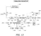
- FIG. 13 illustrates the flow path utilized in the FORMULATION: RECONSTITUTE operation.
- the thick, darkened lines illustrate the flow path for this particular unit operation.
- FIG. 14 illustrates an example of the GUI that is displayed to the user on the computing device that is used to program, control, and analyze data generated by the devices described herein.
- FIG. 15 illustrates an example of the GUI when the formulation subsystem functionality has been selected by the user.
- FIG. 16 illustrates an example of the GUI that is used for data analysis.
- FIG. 2 illustrates an overview of a process for the formulation and concentration of a radiopharmaceutical compound (e.g., PET tracer) according to one embodiment of the invention.
- a radioisotope is first generated or produced as seen in operation 10 .
- the radioisotope is typically generated in a nuclear reactor, cyclotron, or generator. These radioisotopes may be produced on-site or ordered from a third party vendor.
- radioisotopes There are hundreds of radioisotopes that are used for medical applications. Of particular interest for medical imaging applications is the radioisotope fluorine-18 (F-18), which has become a key radioisotope that is used for cancer diagnosis, treatment evaluation, as well as a tool for research into cancer biology and drug development.
- F-18 radioisotope fluorine-18
- Carbon-11 is another example of a radioisotope used in medical imaging applications (C-11). It should be understood, however, that the invention describe herein may be used with any number of radioisotopes.
- a radiopharmaceutical compound such as a PET tracer is synthesized using a radiosynthesizer 100 (illustrated in FIG. 3 ).
- the radiosynthesizer 100 is typically an automated device that is used to perform the chemical synthesis operations that are needed to generate the desired radiopharmaceutical compound.
- the radiosynthesizer 100 contains the reagents needed to generate the radiopharmaceutical compound as well as the flow paths, chemical reaction and other sites needed during the synthesis process.
- a radiosynthesizer 100 is the ELIXYS radiosynthesizer 100 available from Sofie Biosciences (Culver City, Calif.) which is multi-reactor radiosynthesizer 100 that provides the user to perform one, two, or three pot synthesis.
- the ELIXYS radiosynthesizer 100 utilizes a reagent delivery robot for liquid handling and disposable cassettes 102 ( FIG.
- the ELIXYS radiosynthesizer 100 utilizes an intuitive graphical user interface which enables drag-and-drop unit operations to be performed according to the synthesis protocol being used.
- the ELIXYS radiosynthesizer 100 is described, for example, in Claggett et al., Simplified programming and control of automated radiosynthesizers through unit operations, EJNMMI Research, 3: 53 (2013) and in U.S. Patent Application Publication No. 2016/0280734, which are incorporated by reference herein.
- the radiosynthesizer 100 is typically its own separate device (i.e., Device # 1 ).
- radiosynthesizer 100 and the purification and formulation device 200 are illustrated as being two separate devices or modules that coordinate and work together, in another alternative embodiment, the functionality of the radiosynthesizer 100 and the purification and formulation device 200 may be incorporated into a single device.
- a separate purification and formulation device 200 includes functionality to purify and formulate the radiopharmaceutical compound that is generated from radiosynthesizer 100 .
- the radiosythesizer 100 generates a final product that contains contaminants, unreacted products, undesirable solvents and the like that need to be removed prior to use in mammals (e.g., humans).
- radiopharmaceutical compounds are often produced in organic solvents such as acetonitrile, which is toxic above certain concentrations. Prior to being used in the human body, acetonitrile must be brought down to acceptable levels. Similar toxicity profiles exist for other organic solvents and reagents used in the production of radiopharmaceutical compounds. Purification is also needed to remove unwanted radioactive compounds that could interfere with the imaging process.
- the purification and formulation device 200 includes both a purification subsystem 202 as well as a formulation subsystem 204 that purifies the radiopharmaceutical compound to remove unwanted chemical byproducts or reactants as well as, in some embodiments, formulate a final solution that that contains the radiopharmaceutical compound that is ready for use in a mammal.
- formulation may include reducing the concentration of ethanol (EtOH) to allowable levels through the dilution with saline or other aqueous solution. It may also include the addition of compounds that are used to adjust and/or stabilize pH, increase solubility, protect against radiolysis, etc. As seen in FIG.
- this purification and formulation device 200 (i.e., Device # 2 ) performs purification of the radiopharmaceutical compound using HPLC as seen in operation 14 followed by formulation and concentration of the radiopharmaceutical compound as illustrated in operation 16 .
- controller 206 is provided for the control of both the radiosynthesizer 100 and the purification and formulation device 200 .
- a user is able to control and program not only the synthesis operations of the radiosynthesizer 100 but also the operations of the purification and formulation subsystems 202 , 204 .
- FIG. 3 illustrates the integration of the radiosynthesizer 100 and the purification and formulation device 200 through the use of a single controller 206 .
- both the radiosynthesizer 100 and the purification and formulation device 200 are located inside a hot cell 209 .
- a hot cell 209 is a radiation shielded enclosure or working area that contains components that are in contact with radioactive materials.
- the controller 206 is located outside of the hot cell 209 .
- the controller 206 includes a housing 212 that contains an embedded computer 214 that drives or operates the various subsystems of both the radiosynthesizer 100 and the purification and formulation device 200 using software 221 .
- the controller 206 interfaces with the radiosynthesizer 100 and the purification and formulation device 200 via data cables 216 . These may include Ethernet cables and video cables when cameras are integrated into the radiosynthesizer 100 and the purification and formulation device 200 .
- FIG. 3 further illustrates an HPLC pump 218 that interfaces fluidically with the purification and formulation device 200 .
- the HPLC pump 218 is used to push the generated radiopharmaceutical compound from the radiosynthesizer 100 through the purification and formulation device 200 for purification using various liquid mobile phases (e.g., up to four (4) mobile phases may be used in many HPLC pumps). Control of the HPLC pump 218 is also controlled by the controller 206 via its interface with the purification and formulation device 200 .
- the HPLC pump 218 may be located external to the hot cell 209 ( FIG. 3 ), internal to the hot cell 209 , or located within the purification and formulation device 200 .
- FIG. 3 The HPLC pump 218 may be located external to the hot cell 209 ( FIG. 3 ), internal to the hot cell 209 , or located within the purification and formulation device 200 .
- the 3 further illustrates a computing device 208 that is used by the operator to interface with the controller 206 .
- the computing device 208 may include a personal computer, laptop, tablet pc, mobile phone, or the like.
- the computing device 208 contains software 220 located thereon that is used by the operator to access software 221 that is run from the embedded computer 214 to select the operations to be performed by the radiosynthesizer 100 and/or the purification and formulation device 200 .
- GUI graphical user interface
- unit operations include: ADD (for adding a reagent to a reaction vessel); EVAPORATE (for evaporating the contents of a reaction vessel); TRANSFER (for transferring the contents of one reactor to a next reactor; for transfer to an HPLC loop; or for transfer to the HPLC loop on the purification and formulation device 200 ); REACT (seals the reactor vessel to underside of disposable cartridge and heats); PROMPT (pauses sequence run and prompts the user); MOVE (moves a reactor to the front position for reaction vessel removal and/or installation and prompts the user); TRAPF18 (e.g., traps [ 18 F]Fluoride on a quaternary methylammonium (QMA) cartridge); ELUTEF 18 (uses a reagent to elute [ 18 F]Fluoride off a QMA cartridge); MIX (mixes the contents of a reactor by stirring); EXTERNALADD (allows the user to externally add a reagent via tubing);
- the computing device 208 may connect wirelessly (or wired) to the controller 206 using a wireless router or other connection (not shown) typically used to connect electronic devices in a wireless manner.
- computing device 208 may connect to the controller 206 using a secure wireless Wi-Fi network or Bluetooth® connection.
- the software 221 that is executed on the controller 206 that is accessed by the computing device 208 may, in some embodiments, be an application or “app” 220 that is executed on the device 208 . These types of application are common on tablet computers and mobile phone devices.
- the unit operations and their sequence are programmed by the user (e.g., by sequencing serial operations or selecting from pre-set operations) which are then executed by the controller 206 and electronics board 310 to control various computer controlled valves, pumps, and other components including, but not limited to, liquid sensors 274 , 276 , injection valve 240 , column selector valve 242 , UV detector 300 , radiation detector 302 and amplifier 304 , cartridge valve 316 , waste valve 318 , cleaning valve 320 , pressure release valve 324 , pressure regulator 400 set-points, syringe pump 306 , and camera 314 .
- FIG. 4 illustrates a perspective view of the purification and formulation device 200 .
- FIG. 5 illustrates a front facing view of the purification and formulation device 200 .
- the purification and formulation device 200 is contained within a housing 230 that can be positioned in the hot cell 209 adjacent to radiosynthesizer 100 .
- the output line of the radiosynthesizer 100 which is typically polymer tubing is connected to the injection valve 240 of the purification and formulation device 200 via input lines coupled to cassettes 102 .
- FIG. 8 illustrates two such input lines 340 , 342 which may also referred to as “output” lines from the radiosynthesizer 100 .
- line refers to a conduit such as tubing that is used to carry fluid from one point to another.
- Lines can be metallic (e.g., stainless steel) as well as polymer tubing (e.g., 1 ⁇ 8 inch or 1/16 inch O.D. Teflon tubing).
- the injection valve 240 contains ten (10) ports with one of the ports being connected to the output line of the radiosynthesizer 100 . As best seen in FIG. 9 , two of the ports are connected to a first sample loop 344 while another two ports are connected to a second sample loop 346 . Two additional ports on the injection valve 240 lead to waste lines 352 .
- Another port is coupled to the HPLC pump 218 .
- the remaining two ports on the injection valve 240 are connected to the outputs from the radiosynthesizer 100 (which serve as input lines 340 , 342 to the purification and formulation device 200 ). For example, outputs from two different cassettes 102 are connected to the injection valve 240 .
- the injection valve 240 is a bi-state valve and is used to change the position of flow paths. As explained herein, actuation of the injection valve 240 toggles the configuration of the sample loops 344 , 346 between an “injection” position and a “load” position.
- the column selector valve 242 is used to select, during any particular purification run, one of a plurality of columns 243 ( FIG. 8 ) that are held in a column holder 244 is affixed housing 230 .
- the column holder 244 contains clips 246 that are used to hold the individual columns 243 in place.
- Stainless steel or another type of tubing e.g., PEEK
- PEEK polyethylene stylene
- stainless steel or another type of tubing connects the ports on the column selector valve 242 to the individual columns 243 .
- the column selector valve 242 includes pre-column valve components as well as post-column valve components that actuate pre and post column flow paths to selectively place the desired column 243 in the flow path.
- a final product output fitting 248 that is used to connect to flexible tubing that either leads to a final product container 250 (as seen in FIGS. 8, 10-13 ) in one embodiment or, in another embodiment, leads back to the radiosynthesizer 100 .
- This latter configuration is for when an intermediate product may need to be purified and reacted further (e.g., mid-synthesis purification). The intermediate product may undergo purification and then sent back to the radiosynthesizer 100 for additional unit operations (e.g., reactions).
- the fittings described herein are typically flangeless nut fittings or flangeless ferrule fittings which are commonly used for pressurized fluid applications.
- a SPE cartridge 252 is illustrated secured to the face of the formulation device 200 using a clip 254 . Fluid flows through the SPE cartridge 252 via fittings 256 , 258 .
- FIG. 4 also illustrates the dilution reservoir 260 along with corresponding dilution reservoir fittings 262 , 264 , 266 . Each of these fittings serves a different function.
- One fitting 262 is used to deliver a product fraction to the dilution reservoir 260 (i.e., product in).
- Another fitting 264 is used for air vent and also to deliver compressed gas (e.g., nitrogen) to the dilution reservoir 260 to push fluid out of the dilution reservoir 260 for downstream formulation operations.
- compressed gas e.g., nitrogen
- the dilution reservoir 260 includes a removable cap 261 that includes corresponding ports or fittings that corresponding to dilution reservoir fittings 262 , 264 , 266 and tubing which extends into the dilution reservoir 260 .
- a fraction tube holder 268 can hang from the housing 230 and hold fraction tubes 270 . Vials could also be used in place of fraction tubes 270 .
- the fraction tubes 270 are used to collect different fractions obtained after passing through the column 242 and out one of the fraction fittings 272 (four (4) are illustrated but different numbers may be used).
- the outputs from the fraction fittings 272 coupled to the fraction collection valve 322 may themselves be used to route products back to the radiosynthesizer 100 for intermediate purification and further reactions.
- a compressed, inert gas is used to push fluid out of the dilution reservoir 260 in a preferred embodiment, air could also be used to push fluid out of the dilution reservoir 260 .
- the air could be compressed or it may be contained in a syringe or other pumping device that can be actuated to displace liquid in the dilution reservoir 260 .
- FIGS. 4 and 5 also illustrate liquid sensors 274 , 276 . These liquid sensors 274 , 276 are used to detect the presence (or absence) of liquid in the two outputs from the radiosynthesizer 100 . Flexible polymer tubing which connects the respective cassette 102 outputs from the radiosynthesizer 100 is placed in each respective sensor 274 , 276 .
- FIG. 6 illustrates a perspective view of the back side of the purification and formulation device 200 . Two fans 280 , 282 are mounted to the housing 230 and are used to cool the interior electronic and other heat generating components (e.g., UV sensor 300 ).
- Electronic input/output ports 284 are located on the back face of the housing 230 and are used to connect to the internal control electronics via the electronics board 310 including, for example, a video I/O port, HPLC pump port, Ethernet port, etc.
- a switchable power input 286 is provided which connects the purification and formulation device 200 to conventional source of A/C power.
- Three syringe pump inputs or fittings 288 are also provided which connect to inputs used for the syringe pump (e.g., water, saline solution, eluting solution) as described herein.
- An inert gas input 290 is located on the back face of the housing 230 and is connected to a source of inert gas such as nitrogen.
- Three waste ports or fittings 292 are also located on the back face of the housing 230 and connect to flexible tubing (not shown) that leads to waste container(s).
- FIG. 7 illustrates an interior view of the purification and formulation device 200 with a portion of the housing 230 removed.
- a UV detector 300 Located inside the purification and formulation device 200 is a UV detector 300 .
- the UV detector 300 monitors product after traveling through the HPLC column 243 .
- the UV detector 300 can monitor the absorbance of the product(s) passing through polymer tubing at one wavelength between 200 nm and 800 nm.
- Data from the UV detector 300 is transmitted to the controller 206 and then to the computing device 208 where data can be displayed to the user using the graphical user interface 222 as seen in FIG. 14 .
- a radiation detector 302 is located immediately downstream of the UV detector 300 (with respect to flow path) and measures gamma rays emitted by the decaying radioisotope.
- a radiation detector 302 amplifier 304 is also located in the purification and formulation device 200 that is used to amplify the signal from the radiation detector 302 .
- data from the radiation detector 302 is transmitted to the controller 206 and then displayed on the graphical user interface 22 of the computing device 208 .
- Additional detectors could also be incorporated into the flow path. These include, for example, sensors that measure refractive indices, conductivity, and pulsed amperometric detectors (for non-radioactive species).
- a syringe pump 306 is also located in the purification and formulation device 200 and is used during the formulation operations.
- the syringe pump 306 is a six (6) port syringe pump that includes an output port, waste port, one input air port (for pushing residual eluting fluid through the lines when the output of the purification and formulation device 200 returns back to the radiosynthesizer 100 ), and three fluid input ports.
- One port is coupled via a fluid line to container or reservoir (e.g., Falcon tube) that holds water, another is coupled via a fluid line to a container or reservoir that holds saline, and the final input is coupled via a fluid line to a container or reservoir that holds the eluting fluid.
- container or reservoir e.g., Falcon tube
- the final input is coupled via a fluid line to a container or reservoir that holds the eluting fluid.
- An electronics board 310 is also located in the in the purification and formulation device 200 and is used to interface with and control the various sub-systems including the liquid sensors 274 , 276 , injection valve 240 , column selector valve 242 , UV detector 300 , radiation detector 302 , cartridge valve 316 , waste valve 318 , cleaning valve 320 , pressure release valve 326 , pressure regulator 400 , syringe pump 306 , camera 314 .
- Commands and data are communicated with the controller 206 using an Ethernet cable or other communication cable which carries data communications and a video cable that carries the video feed from the camera 314 to the controller 206 .
- the information is read by the software 221 contained on the controller 206 and is then communicated with the computing device 208 for displaying data or assisting the user in making decisions using the GUI 222 .
- a pressure regulator 400 is located in the in the purification and formulation device 200 and is used to regulate the pressure of the inert gas (e.g., nitrogen) that is used to push product from the dilution reservoir 260 during the formulation process as well as being used for cleaning operations.
- a camera 314 is located in the purification and formulation device 200 and is used to generate live video the dilution reservoir 260 which is then transmitted via the controller 206 to the computing device 208 and user interface 222 for viewing ( FIG. 15 ). The camera 314 is focused on the bottom of the dilution reservoir 260 and indicates to the user how much fluid remains in the reservoir. In some concentration and formulation processes, the user may want to ensure that the dilution reservoir 260 has the appropriate amount of fluid and is not fully exhausted which may damage the trapped probe no the SPE cartridge 252 .
- the inert gas e.g., nitrogen
- a series of valves 316 , 318 , 320 , 322 , 324 are located in the purification and formulation device 200 and are used to divert various flow paths as described in more detail below. These include a cartridge valve 316 that is used during the formulation process to deliver fluid containing the product from the dilution reservoir 260 to the SPE cartridge 252 or delivery fluid from the syringe pump 306 to the SPE cartridge 252 . Waste valve 318 is used to divert fluid from the SPE cartridge 252 either to waste or the final product container 250 .
- Cleaning valve 320 is used to send pressurized inert gas (e.g., nitrogen) through various lines for cleaning the purification and formulation device 200 .
- pressurized inert gas e.g., nitrogen
- Fraction collection valve 322 is used to divert fractions to either the fraction tubes 270 to the dilution reservoir 260 for subsequent formulation, or to one of the waste ports 292 on the back of the unit.
- Pressure release valve 324 is used to permit the passage of air during the filling of the dilution reservoir 260 with liquid.
- pressure release valve 324 is also connected to pressurized inert gas which is used to push fluid out of the dilution reservoir 260 and onto the SPE cartridge 252 during the formulation process.
- FIG. 8 illustrates a schematic layout of the flow paths in the purification and formulation device 200 .
- the formulation subsystem 204 is illustrated by the dashed line in FIG. 8 while the purification subsystem 202 includes the remaining components and processes.
- the injection valve 240 is coupled at one port to the HPLC pump 218 via stainless steel tubing (or other type of tubing) which delivers the carrier/mobile phase used for the HPLC separation process. Multiple different carrier/mobile phases can be run through the HPLC pump 218 as well as mixtures of the same.
- FIG. 9 illustrates an enlarged view of the injection valve 240 .
- the injection valve 240 is coupled at another port to a first sample input 340 which, in one embodiment, is the output line from the radiosynthesizer 100 from a first cassette 102 .
- the injection valve 240 is coupled at another port to a second sample input 342 which, in one embodiment, is the output line from the radiosynthesizer 100 from a second cassette 102 .
- Liquid sensors 274 , 276 are located in respective fluid lines that connect each cassette 102 to the ports on the injection valve 240 .
- a first sample loop 344 is connected to two ports on the injection valve 240 which is used to hold sample from the first sample input 340 .
- a second sample loop 346 is connected to two ports on the injection valve 240 which is used to hold sample from the second sample input 342 .
- the sample loops 344 , 346 can contain set volumes of fluid, for example, 5 mL of sample.
- the two sample loops 344 , 346 permit two different purifications runs to be run on the purification and formulation device 200 .
- the injection valve 240 is a two-position valve; when one sample loop (e.g., 344 ) is in the “load” position, the other loop (e.g., 346 ) is in the “inject.” Actuation of the injection valve 240 reverses the respective load and injection positions for the sample loops 344 , 346 . As best seen in FIG. 9 , the second loop 346 is in the “load” position while the first loop 344 is in the “inject” position. Note that in an alternative embodiment, sample may be injected into a sample loop 344 , 346 manually via input lines 340 , 342 using a syringe or the like.
- the injection valve 240 is also coupled to two waste lines 348 , 350 that direct fluid contained therein to waste containers or receptacles 352 .
- the injection valve 240 further includes an output line 354 (e.g., stainless steel) that is connected to the input of the column selector valve 242 .
- the column selector valve 242 is able to connect one of a plurality of columns 243 that may be loaded into the device into the fluid path of the instrument.
- Fraction collection valve 322 also includes a waste line 356 that is connected to a waste container or receptacle 357 via waste ports or fittings 292 .
- the fraction collection valve 322 also includes a product line 358 that diverts product to the dilution reservoir 260 which is already pre-loaded or filled with a volume of high-purity water by the user (capacity is 100 ml) into which the product will become diluted.
- the dilution reservoir 260 also contains an output line 360 that extends into the bottom of the dilution reservoir 260 and is connected at the other end to the cartridge valve 316 .
- the outlet of the cartridge valve 316 is connected to an output line 362 that delivers fluid to the SPE cartridge 252 via port 256 . Fluid exits the SPE cartridge 252 and then passes through port 258 .
- the other inlet of the cartridge valve 316 is coupled to the output line 363 of the syringe pump 306 .
- the syringe pump 306 is a six (6) port syringe pump with another port connected to waste line 364 that connects to a waste container or receptacle 358 via waste ports or fittings 292 . Another port of the syringe pump 306 connects to an input line 366 that connects to a container or receptacle 368 that contains water. Another port of the syringe pump 306 connects to an input line 370 that connects to a container or receptacle 372 that contains a saline solution.
- Still another port of the syringe pump 306 connects to an input line 374 that connects to a container or receptacle 376 that eluting fluid (e.g., ethanol or EtOH).
- Another port of the syringe port 306 is connected to an input line 378 that is open to air 380 that is used to push residual fluid in the fluid carrying lines when product is sent back to the radiosynthesizer 100 for additional unit operations.
- a sterile air filter 381 may be interposed between the air source 380 and the input to the syringe pump 306 .
- the SPE cartridge 252 is coupled to the waste valve 318 via output line 382 .
- the waste valve 318 includes a waste line 384 that connects to the waste container or receptacle 386 via waste ports or fittings 292 .
- the waste valve 318 is also coupled to an output line 388 that delivers product to the final product container 250 .
- the final product container 250 may include a sterile vial containing a septum which is penetrated by a needle or the like that is secured to a sterile filter 390 .
- the final product container 250 may be contained in a lead pig 251 that limits the emission of radiation.
- a vent line 392 is provided along with a sterile filter 394 so that air contained in the final product container 250 can vent out when liquid is delivered to the final product container 250 .
- a pressure regulated inert gas source 400 (e.g., nitrogen) is seen in FIG. 8 connected to the cleaning valve 320 and the pressure release valve 324 .
- the pressurized inert gas source 400 delivers inert gas to the dilution reservoir 260 to push liquid containing the radiopharmaceutical compound into the output line 360 when the pressure release valve 324 is activated.
- the pressurized inert gas source 400 further is used to clean various fluid lines by passing drying inert gas via cleaning valve 320 during a cleaning procedure.
- FIGS. 10-13 illustrate the schematic layout of the flow paths used in the four (4) step FORMULATION unit operations. These include FORMULATION: TRAP ( FIG. 10 ); FORMULATION: RINSE ( FIG. 11 ); FORMULATION: ELUTE ( FIG. 12 ); FORMULATION: RECONSTITUTE ( FIG. 13 ). As seen in FIG. 10 ; FORMULATION: TRAP ( FIG. 10 ); FORMULATION: RINSE ( FIG. 11 ); FORMULATION: ELUTE ( FIG. 12 ); FORMULATION: RECONSTITUTE ( FIG. 13 ). As seen in FIG.
- the pressure release valve 324 and the cartridge valve 316 are actuated so that pressurized inert gas from pressure regulator 400 enters the dilution reservoir 260 and pushes liquid containing the radiopharmaceutical compound into the output line 360 where it enters line 362 and into the SPE cartridge 252 whereby the radiopharmaceutical compound becomes “trapped” on the solid phase sorbent material contained therein (e.g., resin).
- the waste valve 318 is positioned to divert fluid the line 384 and waste container or receptacle 386 .
- the syringe pump 306 is activated to pump water from container or receptacle 368 into output lines 366 , 363 .
- the cartridge valve 316 is actuated to pass the water into line 362 where the contents of the SPE cartridge 252 are washed with water. This removes impurities and cleans the fluid lines of organic solvents.
- the waste valve 318 is positioned to divert fluid the line 384 and waste container or receptacle 386 .
- the volume of rinsing solution may be adjusted using the software 222 on the computing device 208 .
- the syringe pump 306 is activated to pump eluting fluid (e.g., EtOH) from the container or receptacle 376 into output lines 374 , 363 .
- eluting fluid e.g., EtOH
- the cartridge valve 316 is actuated to pass the eluting fluid into line 362 where the radiopharmaceutical compound that is trapped in the SPE cartridge 252 elutes off the solid phase sorbent material and into the eluting liquid.
- the waste valve 318 is actuated to pass this eluting fluid into output line 388 where is passes through the sterile filter 390 and into the final product container 250 .
- the syringe pump 306 is activated to pump a saline solution or fluid (e.g., phosphate buffered saline) from the container or receptacle 372 into output lines 370 , 363 .
- the cartridge valve 316 is actuated to pass the saline solution or other buffered aqueous solution into line 362 and through the SPE cartridge 252 .
- the waste valve 318 is actuated to pass this saline solution into output line 388 where is passes through the sterile filter 390 and into the final product container 250 .
- This step of the FORMULATION operation allows any residual organic solvents or other unwanted compounds to be diluted to an acceptable level so that the radiopharmaceutical compound is ready for use.
- the syringe pump 306 never encounters any crude or purified product or any of the solvents that may be involved in the TRAP operation.
- the syringe pump 306 is only programmed to use the fluid path 363 as the output line; it never aspirates fluid through this line.
- the source of air 380 is pumped by the syringe pump 306 through the sterile filter 381 and into the downstream lines 363 , 388 to chase the ethanol or other eluting fluid through the lines.
- the purification and formulation device 200 may also utilize an automated cleaning operation for both the purification 202 and formulation 204 flow paths.
- a mobile phase is pumped by an HPLC pump 218 through the injector valve 240 , column selector valve 242 , column(s) 243 , UV detector 300 , radiation detector 302 , cleaning valve 320 , fraction collection valve 322 , product line 358 , waste line 356 , and the lines (e.g., four) connected to the fraction containers 270 .
- the mobile phase is collected the dilution reservoir 260 as well as fraction containers 270 .
- the HPLC pump 218 turns off.
- the cleaning valve 320 then activates and the pressure regulator 400 outputs compressed inert gas for a programmed time and at a programmed pressure.
- the fraction collection valve 322 cycles between all outputs (described above) to thoroughly dry the lines.
- the formulation clean operation cleans the valves and lines used in the FORMULATION operations ( FIGS. 10-13 ).
- the dilution reservoir 260 is filled with ethanol (e.g., 100 mL) and the saline line 370 and water line 366 are placed in a waste container.
- a cleaning solution e.g., ethanol
- the final product line 388 is also placed in a waste container.
- the SPE cartridge 252 is removed and the input/output fittings 256 , 258 are connected together.
- the syringe pump 306 aspirates the cleaning solution or air to rinse and dry all formulation subsystem 204 fluid paths. Again, both cleaning operations may be performed automatically by the controller 206 .
- FIG. 14 illustrates an example of the GUI 222 that is displayed to the user on the computing device 208 .
- the user is given current information from the purification subsystem 202 regarding a current purification process being run on the purification and formulation device 200 .
- the GUI 222 includes a navigation button 500 as well as indicates which subsystem is selected (i.e., purification subsystem 202 or formulation 204 subsystem) by indicator 502 (in FIG. 14 purification is selected but for formulation, indicator 502 will be moved to indicate selection of the formulation operation as seen in FIG. 15 ).
- the GUI 222 provides the user with the selected pathway of the fraction collection valve 322 (i.e., product line 358 , fraction 270 , or waste 356 ).
- the fraction collection valve 322 is diverting product as seen by highlighted selection 504 .
- the GUI 222 further includes a graphing screen 506 that provides live data from the UV detector 300 and/or the radiation detector 302 .
- Various graphing options are provided as seen in option menu 508 . These options include AU (for UV graphs), mV (for radiation graphs), output overlay, record, clear, and zero.
- the GUI 222 also provides a panel of information 510 for control and feedback. This panel 510 displays current operational conditions and configurations of the purification subsystem 202 .
- various fractions that are separated in the purification subsystem may be selected by the user using a touch button found on the GUI 222 such that the particular fraction is delivered to the fraction collection tubes or vials 270 or delivered as the product to the dilution reservoir 260 .
- This is a process whereby fractions are manually selected by the user.
- the software itself can be programmed to automatically select various fractions for shunting to either the collection tubes or vials 270 or the main product line 358 .
- Automated control of the fraction collection valve 322 may look to real time or near real time data generated by the UV detector 300 and radiation detector 302 as well as known elapsed elution times of purified product from the columns 243 to identify suspect or desired fractions of interest. Peak detection algorithms may look at designated time windows and/or set threshold values for the output of UV and/or radiation peaks which can then be used to trigger actuation of the fraction collection valve 322 .
- FIG. 15 illustrates an example of the GUI 222 that is displayed to the user on the computing device 208 when the formulation subsystem 204 is selected by the user as indicated by indicator 502 .
- a step selection menu 512 is provided to the user to program and monitor various aspects of the formulation operation. This includes the TRAP operation, the RINSE operation, the ELUTE operation, and the RECONSTITUTE operation.
- the user is provided with a control window 514 that can be used to adjust various operational parameters via edit button 516 .
- GUI 222 also illustrates a live video image 518 of the dilution reservoir 260 taken with camera 314 .
- FIG. 16 illustrates another example of the GUI 222 that is displayed to the user on the computing device 208 and used for data analysis.
- a graph window 520 is provided that is used to display UV data, radiation data, or both.
- Buttons 522 are selected or deselected to display or hide the desired data. Fractions, if not already named, can be manually named using fraction naming fields 524 .
- the GUI 222 also provides the user the ability to analyze various peaks present in the data fields. For example, the user is able to perform a baseline peak area calculation using baseline button 526 . In this example, the radiation detector data is analyzed for peak # 1 . After identifying the peak and baseline, the software automatically calculates peak area, peak time, and peak height which are displayed in peak output window 528 .
- Peak area may also be expressed as a percentage of the total area, for example, by depressing the area button 529 (which toggles between absolute and percentage values).
- Point-to-point calculation for peak areas is performed using the point-point button 530 as illustrated in FIG. 16 . In peak-to-peak calculation two points are defined that define a line to which the peak is integrated.
- Data can be exported using export buttons 532 (e.g., batch data or raw .CSV data). Analysis data may be saved or cleared using save button 534 and clear button 536 .
Landscapes
- Chemical & Material Sciences (AREA)
- Organic Chemistry (AREA)
- Chemical Kinetics & Catalysis (AREA)
- Engineering & Computer Science (AREA)
- Manufacturing & Machinery (AREA)
- Medicines Containing Antibodies Or Antigens For Use As Internal Diagnostic Agents (AREA)
Abstract
Description
Claims (20)
Priority Applications (1)
| Application Number | Priority Date | Filing Date | Title |
|---|---|---|---|
| US15/698,350 US10589250B2 (en) | 2016-09-07 | 2017-09-07 | Automated purification and formulation device for radiopharmaceutical compounds |
Applications Claiming Priority (2)
| Application Number | Priority Date | Filing Date | Title |
|---|---|---|---|
| US201662384490P | 2016-09-07 | 2016-09-07 | |
| US15/698,350 US10589250B2 (en) | 2016-09-07 | 2017-09-07 | Automated purification and formulation device for radiopharmaceutical compounds |
Publications (2)
| Publication Number | Publication Date |
|---|---|
| US20180065103A1 US20180065103A1 (en) | 2018-03-08 |
| US10589250B2 true US10589250B2 (en) | 2020-03-17 |
Family
ID=61281898
Family Applications (1)
| Application Number | Title | Priority Date | Filing Date |
|---|---|---|---|
| US15/698,350 Active 2038-03-25 US10589250B2 (en) | 2016-09-07 | 2017-09-07 | Automated purification and formulation device for radiopharmaceutical compounds |
Country Status (1)
| Country | Link |
|---|---|
| US (1) | US10589250B2 (en) |
Cited By (2)
| Publication number | Priority date | Publication date | Assignee | Title |
|---|---|---|---|---|
| US12078625B2 (en) | 2019-04-25 | 2024-09-03 | The Regents Of The University Of California | System and method for high-throughput radio thin layer chromatography analysis |
| US12564840B2 (en) | 2019-08-08 | 2026-03-03 | The Regents Of The University Of California | High throughput radiochemistry system |
Families Citing this family (4)
| Publication number | Priority date | Publication date | Assignee | Title |
|---|---|---|---|---|
| US10895563B2 (en) | 2014-02-26 | 2021-01-19 | Trace-Ability, Inc. | Palette-based systems for analyte characterization |
| US11002717B2 (en) * | 2014-02-26 | 2021-05-11 | Trace-Ability, Inc. | Systems and methods for characterizing radioactive analytes |
| BE1030296B1 (en) * | 2022-02-24 | 2023-09-19 | Out And Out Chemistry | Collection system for the recovery of a separated radioactive fraction |
| CN116216301B (en) * | 2023-05-06 | 2023-07-04 | 成都德力斯实业有限公司 | Radioactive sterile injection production line |
Citations (8)
| Publication number | Priority date | Publication date | Assignee | Title |
|---|---|---|---|---|
| US20060245980A1 (en) | 2005-05-01 | 2006-11-02 | Iba Molecular North America, Inc | Apparatus and method for producing radiopharmaceuticals |
| JP2009047454A (en) | 2007-08-14 | 2009-03-05 | Sumitomo Heavy Ind Ltd | Ri compound synthetic apparatus |
| US7586102B2 (en) | 2006-08-14 | 2009-09-08 | Board Of Regents The University Of Texas System | Automated system for formulating radiopharmaceuticals |
| US7897935B2 (en) | 2008-11-06 | 2011-03-01 | Quark Technologies Australia Pty Ltd. | Radiopharmaceutical purification |
| US20120108858A1 (en) | 2010-10-28 | 2012-05-03 | Maxim Kiselev | Method and device for manufacturing of radiopharmaceuticals |
| KR20130002795A (en) | 2011-06-29 | 2013-01-08 | 박태권 | Structure for installing support of exercise apparatus for whole body |
| US20130020727A1 (en) | 2011-07-15 | 2013-01-24 | Cardinal Health 414, Llc. | Modular cassette synthesis unit |
| WO2014160799A1 (en) | 2013-03-26 | 2014-10-02 | The Regents Of The University Of California | An automated, multi-pot high-pressure radio-synthesizer for production of pet tracers |
-
2017
- 2017-09-07 US US15/698,350 patent/US10589250B2/en active Active
Patent Citations (9)
| Publication number | Priority date | Publication date | Assignee | Title |
|---|---|---|---|---|
| US20060245980A1 (en) | 2005-05-01 | 2006-11-02 | Iba Molecular North America, Inc | Apparatus and method for producing radiopharmaceuticals |
| US7586102B2 (en) | 2006-08-14 | 2009-09-08 | Board Of Regents The University Of Texas System | Automated system for formulating radiopharmaceuticals |
| JP2009047454A (en) | 2007-08-14 | 2009-03-05 | Sumitomo Heavy Ind Ltd | Ri compound synthetic apparatus |
| US7897935B2 (en) | 2008-11-06 | 2011-03-01 | Quark Technologies Australia Pty Ltd. | Radiopharmaceutical purification |
| US20120108858A1 (en) | 2010-10-28 | 2012-05-03 | Maxim Kiselev | Method and device for manufacturing of radiopharmaceuticals |
| KR20130002795A (en) | 2011-06-29 | 2013-01-08 | 박태권 | Structure for installing support of exercise apparatus for whole body |
| US20130020727A1 (en) | 2011-07-15 | 2013-01-24 | Cardinal Health 414, Llc. | Modular cassette synthesis unit |
| WO2014160799A1 (en) | 2013-03-26 | 2014-10-02 | The Regents Of The University Of California | An automated, multi-pot high-pressure radio-synthesizer for production of pet tracers |
| US20160280734A1 (en) | 2013-03-26 | 2016-09-29 | The Regents Of The University Of California | An automated, multi-pot high-pressure radio-synthesizer for production of pet tracers |
Non-Patent Citations (26)
| Title |
|---|
| Ackermann, Uwe et al., Fully automated synthesis and coupling of [18F]FBEM to glutathione using iPHASE FlexLab module, J. Label Compd. Radiopharm 2014, 57, 115-120. |
| Ackermann, Uwe et al., Synthesis of F-18 Fluoroestradiol Using the Flexlab Radiosynthesizer, Centre for PET, Austin Hospital, Studley Road, Melbourne VIC 3084, Australia, Ludwig Institute for Cancer Research, Melbourne Centre for Clinical Sciences, Eastern Heal, Box Hill Hospital, undated, (1page). |
| Alauddin, Mian M. et al., Synthesis of [18F]-labeled 72′-deoxy-2′-fluoro-5-methyl-1-B-D-arabinofuranosyluracil([18F]-FMAU), J Label Compd Radiopharm 2002; 45: 583-590. |
| Alauddin, Mian M. et al., Synthesis of [18F]-labeled adenosine analogues as potential PET imaging agents, J Label Compd Radiopharm 2003; 46: 805-814. |
| Anderson, Harry et al., Improved synthesis of 2′-deoxy-2′[18F]-fluoro-1-B-D-arabinofuranosyl-5-iodouraci ([18F]-FIAU), Nuclear Medicine and Biology 37 (2010) 439-442. |
| Cai, Hangcheng et al., The improved synthesis of 5-substituted 2′[18F]fluoro-2′-deoxy-arabinofuranosyluracil derivatives ([18F]FEAU, [18F]FFAU, [18F]FCAU, [18F]FBAU and [18F]FIAU) using a multistep one-pot strategy, Nuclear Medicine and Biology 38 (2011) 659-666. |
| Chin, Frederick T. et al., Semiautomated Radiosynthesis and Biological Evaluation of [18F]FEAU: A Novel PET Imaging Agent for HSV1-tk/sr39tk Reported Gene Expression, Mol Imaging Biol (2008) 10:82-91. |
| Claggett, Shane B et al., Simplified programming and control of automated radiosynthesizers through unit operations, EJNMMI Research 2013, 3:53 (13pages). |
| Coenen, H.H. et al., Fluorine-18 radiopharmaceuticals beyong [18F]FDG for use in oncology and neurosciences, Nuclear Medicine and Biology 37 (2010) 727-740. |
| Explora FM, Explora FM Formulation Module, http://www.siemens.com, Siemens Healthcare Limited-2017-(1page). |
| Explora FM, Explora FM Formulation Module, http://www.siemens.com, Siemens Healthcare Limited-2017—(1page). |
| Goh, Yit Wooi et al., Fully automated Click radiolabeling for [18F] FLETT and the synthesis and coupling of [18F]FBEM to glutathione using the iPHASE FlexLab module, Centre for PET, Austin Health, Heidelberg, Australia, The University of Melbourne, Australia, Ecole Nationale Superieure de Chimie de Rennes, France, IPHASE technologies, Australia, undated, (1page). |
| Herman, Henry et al., Flexible radiosynthesizer capable of multi-pot high temperature and pressure reactions, Crump Institute Molecular Imaging, UCLA, Department of Molecular & Medical Pharmacology, UCLA, Sofie Biosciences, Inc. (Abstract) (2011) (1page). |
| Herman, Henry et al., Flexible radiosynthesizer capable of multi-pot high temperature and pressure reactions, Crump Institute Molecular Imaging, UCLA, Department of Molecular & Medical Pharmacology, UCLA, Sofie Biosciences, Inc. (PPT) (2011) (24pages). |
| Herman, Henry et al., Multi-pot radiosynthesizer capable of high-pressure reactions for production of [18F]FAC and analogs, J. Nucl Med. 2011; 52 (Supplement 1):1440. |
| Keng, Pei Yuin et al., Emerging Technologies for Decentralized Production of PET Tracers, Positron Emission Tomography-Current Clinical and Research Aspects, www.intechopen.com, InTech; 2012; 153-182. |
| Keng, Pei Yuin et al., Emerging Technologies for Decentralized Production of PET Tracers, Positron Emission Tomography—Current Clinical and Research Aspects, www.intechopen.com, InTech; 2012; 153-182. |
| Li, Zibo et al., Automated synthesis of 2′-deoxy-2′-[18F]fluoro-5-methyl-1-B-D-arabinofuranosyluracil ([18F]-FMAU) using a one reactor radiosynthesis module, Nuclear Medicine and Biology 38 (2011) 201-206. |
| Moore, Melissa D. et al., ARC-P HS+: A versatile radiosynthesizer for the production of PET tracers, AACR Annual Meeting, Mar. 31-Apr. 4, 2012, Chicago, IL (1page). |
| Paolillo, Vincenzo et al., A fully automated synthesis of [18F]-FEAU and [18F]-FMAU using a novel dual reactor radiosynthesis module, J. Label Compd. Radiopharm 2009, 52, 553-558. |
| Patt, Marianne et al., Fully automated radiosynthesis of both enantiomers of [18F]Flubatine under GMP conditions for human application, Applied Radiation and Isotopes 80 (2013) 7-11. |
| PCT International Preliminary Report on Patentability (Chapter I of the Patent Cooperation Treaty) for PCT/US2014/031905, Applicant: The Regents of the University of California, Form PCT/IB/326 and 373, dated Oct. 8, 2015 (7pages). |
| PCT International Search Report for PCT/US2014/031905, Applicant: The Regents of the University of California, Form PCT/ISA/210 and 220, dated Jul. 25, 2014 (5pages). |
| PCT Written Opinion of the International Search Authority for PCT/US2014/031905, Applicant: The Regents of the University of California,, Form PCT/ISA/237, dated Jul. 25, 2014 (5pages). |
| Product Description and Specification, Catalog No. 4, Syntra RNplus Research, Synthra GmbH, Albert-Einstein-Ring 21, D-22761 Hamburg, Germany (2015). |
| Sachinidis, John I et al., Automation for Optimised Production of Fluorine-18-Labelled Radiopharmaceuticals, Current Radiopharmaceuticals, 2010, 3, 248-253. |
Cited By (2)
| Publication number | Priority date | Publication date | Assignee | Title |
|---|---|---|---|---|
| US12078625B2 (en) | 2019-04-25 | 2024-09-03 | The Regents Of The University Of California | System and method for high-throughput radio thin layer chromatography analysis |
| US12564840B2 (en) | 2019-08-08 | 2026-03-03 | The Regents Of The University Of California | High throughput radiochemistry system |
Also Published As
| Publication number | Publication date |
|---|---|
| US20180065103A1 (en) | 2018-03-08 |
Similar Documents
| Publication | Publication Date | Title |
|---|---|---|
| US10589250B2 (en) | Automated purification and formulation device for radiopharmaceutical compounds | |
| US9481705B2 (en) | Modular radiochemistry synthesis system | |
| US9063158B2 (en) | Multi-stream high-pressure liquid chromatography module | |
| CA2823918C (en) | Modular system for radiosynthesis with multi-run capabilities and reduced risk of radiation exposure | |
| US20250258147A1 (en) | Radiopharmaceutical Production System and Quality Control System Utilizing High Performance Liquid Chromatography | |
| US20110008215A1 (en) | Modular system for radiosynthesis with multi-run capabilities and reduced risk of radiation exposure | |
| JP2009501138A (en) | System and method for processing chemical substances, computer program for controlling such a system, and computer-readable storage medium | |
| JP2010531295A (en) | Microfluidic Radiosynthesis System for Positron Emission Tomography Biomarkers (Related Application) This application is a US Provisional Application No. 60 / 923,086 filed Apr. 12, 2007, April 2007. U.S. Provisional Application No. 60 / 923,407 filed on Jan. 13, U.S. Patent Provisional Application No. 11 / 895,636, filed Aug. 23, 2007, and Jan. 2008 Claims priority based on US Provisional Patent Application No. 61 / 010,822, filed on Jan. 11, the contents of each of which are incorporated herein by reference in their entirety. | |
| US10473668B2 (en) | Self-shielded, benchtop radio chemistry system with a plurality shielded carriers containing a disposable chip cassette | |
| US20130023657A1 (en) | System for radiopharmaceutical preparation involving solid and liquid phase interactions | |
| US20140213757A1 (en) | Cassette for radiopharmaceutical synthesis | |
| US11846621B2 (en) | Method of determining radiation characteristic of a sample | |
| US20150160171A1 (en) | Automated Quality Control System for Radiopharmaceuticals | |
| Mc Veigh et al. | Microfluidic synthesis of radiotracers: recent developments and commercialization prospects | |
| EP2650681B1 (en) | Radiopharmaceutical production system and quality control system utilizing high performance liquid chromatography | |
| Schopf et al. | Automation of a positron-emission tomography (PET) radiotracer synthesis protocol for clinical production | |
| US10065985B2 (en) | Method for fully automated synthesis of 16β-18F-fluoro-5α-dihydrotestosterone (18F-FDHT) | |
| WO2016130458A1 (en) | Automated quality control system for radiopharmaceuticals | |
| JPH07318695A (en) | Method and apparatus for automatically synthesizing compound containing radioactive nuclide | |
| Satyamurthy et al. | Modular radiochemistry synthesis system | |
| Diaz et al. | Development and validation of a semi-automated [13N] Ammonia preparation system for clinical research | |
| Ruth et al. | Automated radiochemistry through transducers: Light from the far side |
Legal Events
| Date | Code | Title | Description |
|---|---|---|---|
| FEPP | Fee payment procedure |
Free format text: ENTITY STATUS SET TO UNDISCOUNTED (ORIGINAL EVENT CODE: BIG.); ENTITY STATUS OF PATENT OWNER: SMALL ENTITY |
|
| FEPP | Fee payment procedure |
Free format text: ENTITY STATUS SET TO SMALL (ORIGINAL EVENT CODE: SMAL); ENTITY STATUS OF PATENT OWNER: SMALL ENTITY |
|
| AS | Assignment |
Owner name: THE REGENTS OF THE UNIVERSITY OF CALIFORNIA, CALIFORNIA Free format text: ASSIGNMENT OF ASSIGNORS INTEREST;ASSIGNOR:VAN DAM, R. MICHAEL;REEL/FRAME:044133/0159 Effective date: 20170910 Owner name: THE REGENTS OF THE UNIVERSITY OF CALIFORNIA, CALIF Free format text: ASSIGNMENT OF ASSIGNORS INTEREST;ASSIGNOR:VAN DAM, R. MICHAEL;REEL/FRAME:044133/0159 Effective date: 20170910 |
|
| AS | Assignment |
Owner name: NATIONAL INSTITUTES OF HEALTH (NIH), U.S. DEPT. OF HEALTH AND HUMAN SERVICES (DHHS), U.S. GOVERNMENT, MARYLAND Free format text: CONFIRMATORY LICENSE;ASSIGNOR:UNIVERSITY OF CALIFORNIA LOS ANGELES;REEL/FRAME:044229/0665 Effective date: 20171018 Owner name: NATIONAL INSTITUTES OF HEALTH (NIH), U.S. DEPT. OF Free format text: CONFIRMATORY LICENSE;ASSIGNOR:UNIVERSITY OF CALIFORNIA LOS ANGELES;REEL/FRAME:044229/0665 Effective date: 20171018 |
|
| STPP | Information on status: patent application and granting procedure in general |
Free format text: DOCKETED NEW CASE - READY FOR EXAMINATION |
|
| STPP | Information on status: patent application and granting procedure in general |
Free format text: NON FINAL ACTION MAILED |
|
| STPP | Information on status: patent application and granting procedure in general |
Free format text: NOTICE OF ALLOWANCE MAILED -- APPLICATION RECEIVED IN OFFICE OF PUBLICATIONS |
|
| STPP | Information on status: patent application and granting procedure in general |
Free format text: PUBLICATIONS -- ISSUE FEE PAYMENT VERIFIED |
|
| STCF | Information on status: patent grant |
Free format text: PATENTED CASE |
|
| MAFP | Maintenance fee payment |
Free format text: PAYMENT OF MAINTENANCE FEE, 4TH YR, SMALL ENTITY (ORIGINAL EVENT CODE: M2551); ENTITY STATUS OF PATENT OWNER: SMALL ENTITY Year of fee payment: 4 |
|
| AS | Assignment |
Owner name: JPMORGAN CHASE BANK, N.A., AS COLLATERAL AGENT, NEW YORK Free format text: SECURITY INTEREST;ASSIGNOR:SOFIE BIOSCIENCES, INC.;REEL/FRAME:067581/0341 Effective date: 20240531 |