US1058877A - Typographic composing-machine. - Google Patents
Typographic composing-machine. Download PDFInfo
- Publication number
- US1058877A US1058877A US51977309A US1909519773A US1058877A US 1058877 A US1058877 A US 1058877A US 51977309 A US51977309 A US 51977309A US 1909519773 A US1909519773 A US 1909519773A US 1058877 A US1058877 A US 1058877A
- Authority
- US
- United States
- Prior art keywords
- matrices
- distributer
- box
- magazines
- teeth
- Prior art date
- Legal status (The legal status is an assumption and is not a legal conclusion. Google has not performed a legal analysis and makes no representation as to the accuracy of the status listed.)
- Expired - Lifetime
Links
- 239000011159 matrix material Substances 0.000 description 30
- 230000000153 supplemental effect Effects 0.000 description 11
- 241000239290 Araneae Species 0.000 description 7
- 238000010276 construction Methods 0.000 description 5
- 230000001965 increasing effect Effects 0.000 description 4
- 230000000284 resting effect Effects 0.000 description 3
- 238000005266 casting Methods 0.000 description 2
- 230000001419 dependent effect Effects 0.000 description 2
- 230000003028 elevating effect Effects 0.000 description 2
- 230000005484 gravity Effects 0.000 description 2
- 230000000717 retained effect Effects 0.000 description 2
- 238000000926 separation method Methods 0.000 description 2
- 240000007594 Oryza sativa Species 0.000 description 1
- 235000007164 Oryza sativa Nutrition 0.000 description 1
- 238000000034 method Methods 0.000 description 1
- 235000009566 rice Nutrition 0.000 description 1
- 239000011435 rock Substances 0.000 description 1
Images



Classifications
-
- B—PERFORMING OPERATIONS; TRANSPORTING
- B41—PRINTING; LINING MACHINES; TYPEWRITERS; STAMPS
- B41B—MACHINES OR ACCESSORIES FOR MAKING, SETTING, OR DISTRIBUTING TYPE; TYPE; PHOTOGRAPHIC OR PHOTOELECTRIC COMPOSING DEVICES
- B41B11/00—Details of, or accessories for, machines for mechanical composition using matrices for individual characters which are selected and assembled for type casting or moulding
- B41B11/18—Devices or arrangements for assembling matrices and space bands
Definitions
- My invention relates to improvements in typographic composing machines of the class which uses matrices having one or more characters thereon; the matrices after being used to produce a type or line of type are distributed automatically into a magazine.
- the object of my invention is to provide means whereby a greater number of different fonts of matrices may be available without changing the font in the magazine or changing the magazine with the font therein.
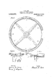
- To accomplish this I provide a plurality of magazines and mechanism for distributing matrices of different fonts into their respective magazines. I attain these objects by the mechanism illustrated in the accompanying drawings, in which Figure 1, is a top view with .a portion of the distributer ring and plate removed; Fig. 2, is a vertical section on line a, u, Fig. 1;
- Fig. 3 is a top view of the magazine and their supporting framework
- Fig. 4 is a vertical section of the distributer rings on line a), c, Fig. 1 and w, to, Fig. 5
- Fig. 5 is a view of a portion of the distributer rings projected on a straight line
- Fig. 6, is an elevation of the separating boxes, with one side of one of the boxes removed
- Fig. 7 is an end elevation partly in section of the separating boxes on line m, m, Fig. 6
- Fig. 8 is
- Fig. 9 is a view of a portion of the distributer rings projected on a straight line
- Fig. 10 is a vertical cross section of the distributer rings on linez, a
- Fig. 11, is an elevation of the elevator
- Figs. 12, 13, and 14 are face views of the several cams, for operating various parts of the mechanism
- Fig. 15, is an inverted plan view of several different matrices showing the grooves which reduce all the matrices at one point to a common thickness.
- A, a, B, 7), C, 0, and D are the magazines which are arranged in the form of a ring, about a cen- Specification of Letters Patent.
- F, and f are the distributer rings upon which the matrices are conveyed to their proper channel in the magazines.
- the G is the conveyer having the buckets H, and it, into which the matrices drop from the distributer boxes.
- the buckets H. and h. are similar to each other, but are arranged in concentric circles, the buckets it. being toward the center of the conveyer G.
- These buckets consist of rectangular buckets open at the top and bottom so that the matrices can enter through their top opening and leave through the bottom.
- the purpose of these buckets is to prevent the matrices from becoming dislodged from the distributing rings by lateral or other movements, before they reach their respective channels in the magazines; and the matrices therefore hang .loosely into the buckets from the distributing rings while traveling from the separating device to the several channels of the magazines.
- the conveyer G has a rotating movement by means of which the matrices after dropping into the conveyer buckets are moved onto and along the distributer rings.
- the chutes K, and Ir are the magazine chutes through which the matrices are guided to their respective channels in the magazines.
- the chutes K, and 7s guide the matrices, as they are released from the distributer rings, into alternate channels in the magazines, the chute K, guiding the matrices released from the distributer ring F, into alternate channels 'in the magazines, while the chute Z0, guides ,the matrices released from the distributer ring f, into the channels adjacent to and alternate with the channels which receive the matrices from the chute K.
- R is the elevator which takes the matrices after a line has been cast and lifts them up to a position ready for separation and distribution.
- the elevator comprises a bar 1 having teeth, representing the full matrix combination, and therefore adapted to receive the matrices longitudinally thereon and retain them during the elevating operation.
- the horizontal bar 1, is carried by the upright plate 2, which has a sliding dovetail connection with the upright 3, by which are fed longitudinally upon the teeth of the bar 1, while the latter is in its lowered position in the usual manner; and the bar 1, is elevated to the position shown in Fig. .6,
- the bar 2 is vertically guided.
- the matrices when the matrices are in position to be received in the separating boxes.
- N. and n are separating boxes, arranged preferably side by side in the same plane and in line with the bar 1, of the elevator, when the latter is in its raised position.
- the box N. is in direct line with the bar 1, and receives all the matrices from the latter,
- the box at. is arranged to one side of the box N. and receives its matrices from the box N.
- the matrices from the elevating bar 1 to the separating box N. they are arranged to lie in sets in the box N. in such different relative positions that the separating device will be able to select certain of the matrices from the box N. for distribution to the box n.
- matrices e. have slots 34, at the top and through these slots the matrices are divided into allotments.
- a plate 35 Depending downwardly in the box N. is a plate 35, preferably slanting at its front end as shown in Fig. 6, and extending upwardly from the bottom of the box N. is a plate 36; both ofwhich are preferably extended beyond thebox n. toward the bar 1.
- the plates 35, and 36 tend to separate the matrices E. and 6. so that they will lie in different horizontal planes when they come into the box N.
- those matrices 0, having the slot 34:, in their upper edge will straddle the plate 35. and as they have no slot in the bottom, they will be raised by the plate 36 and will travel into box N. on the higher level.
- the matrices E, having the slot 33, in their lower end will straddle the plate 36, but as they.
- the plates 37, which support the matrices in the box N. are preferably extended beyond the gap between the bar 1, and box N. so that the matrices will be prevented from falling while being transferred to box N.
- the matrices E. and 6, will now lie in the position shown in the right of Fig. 7, the matrices 6, being raised slightly above the matrices E.
- the matrices e, in box N. are to be separated from the matrices E. and are to be placed in the box n. Just previous to feeding the matrices into the box n. the elevator O. is lowered so that the plate 21, which has a V shaped rail, the notches of which correspond to a full matrix combination, is in line w1th the combination of the upper matrices, a.
- the matrices When the matrices are moved into the box N. and caused to travel on different planes, the matrices 0, will engage on the teeth of the plate 21, of the elevator while the matrices E. which travel on the lower plane will not engage the elevator.
- the elevator O. is raised by mechanism set forth herein to carry the matrices 0, out of the box N. and is moved laterally, over the box n. and is lowered, sufficient to present the matrices 6, into the box a.
- This completes the allotment and the box N. may if both matrices E, and e are being used simultaneously in the machine, have matrices E, while the matrices 6, will be suspended from theelevator rail 21, in the box a. I prefer to fulcrum the plate 22, of the elevator upon the arm 23, so that it may swing slightly.
- the M and m are the distributer boxes from which the allotments of matrices are distributed to the conveyer G.
- the box M. is in line with the separating box N. while the box m is in line with the box at.
- the boxes M and m are provided with bottom rails 43, which support the matrices and with side rails 42, which engage the side recesses of the matrices and on these rails 42, and 43, the matrices travel when passing from the boxes N. and n to the conveyer.
- To move matrices in the separating and distributing boxes I provide a slide consisting of a plate P. the part 5, of which is connected witha slide 6, which travels in a guide pocket 4:; and the slide 6, is connected with a link 8, which latter is fulcrumed to the end of a lever 7.
- the plate P When the elevator bar 1, is raised, the plate P, is withdrawn beyond the matrices in the elevator.
- the plate P. is moved forward by lever 7 to force the matrices from the bar 1, into the separating box N. when the movement of plate P ceases, by reason of the shape of the cam 12, long enough for the elevator O. to take the matrices c from the box N. and place them in a.
- the plate P. is then farther advanced and causes the matrices E. in box N to move into the distributer box M and the matrices e in box at will be moved into box m. This will cause any matrices which were previously in the distributer boxes M and m to feed toward the escapement device.
- the bell crank lever 7, is actuated through the link 9, and the cam lever 10, movable in guide 11.
- the cam lever 10 is actuated by the cam 12, through the cam roller 13.
- the cam 12, is secured to the shaft 14, which receives its motion through the bevel gear 15, on the shaft 1 1, and the bevel gear 16, on the vertical shaft 18, movable in bearings 19, in the column 20, and actuated by anysuitable means at the base of the column, not shown.
- the matrix slide cam 12 through intermediate connections actuates the matrix slide in its outward motion while its inward motion to move the line of matrices into the separating boxes and from the separating boxes into the distributer boxes is accomplished by means of the spring 17.
- the lever 23, is connected at its fulcrum end to the slide 27, movable in the guide 28; the cam lever 24, is connected at its fulcrum end to the guide 28, and has the cam roller 26, through which the lever 24, is actuated by the cam 25 on the shaft 14.
- the cam lever 24, is connected to the lever 23, by the link 32, by which means the movement of the cam lever 24, is transferred to the lever 23, causing it to raise matrices 6, out of the box N, and lower them into the box a.
- connection 29, has a roller 31, through which it is actuated by the cam 30, on the shaft 14, causing the slide 27 to reciprocate in its guide 28, by which means the lever 23, afterraising the matrices 6, out of the box N, is moved to such a position that the matrices are over the box n, when the matrices are lowered into the box a, by the ac tion of the cam 25, the lever 24, and the lever 23.
- the tilting rail 38 is designed to be moved to admit the passage of the matrices e, and after the matrices 6, pass the tilting rail 38, it is moved to its normal position by the spring 107, thereby preventing the matrices E, from assuming The rail 38 rocks on a pintle 38 and, when the matrices e, are
- the matrices E, and e have the separating grooves 39 extending inwardly from one face thereof, by which the matrices are 1 all reduced to the same thickness at that point by which means a thick matrix is caused to pass the separators 47 in the dis tributer boxes M, and m, while only one boxes N, and a.
- the boxes M, and m are;
- the separators 47 shown in Fig. 6, and in dotted lines in Fig. 8, are thin plates which enter the matrix separator grooves 39, as the matrix passes downward in the act of being released from the distributer boxes, thus preventing more than one matrix from passing out of each of the boxes at one time.
- the separators are of similar construction to ones in use in devices of this class and are therefore well known in the art.
- the distributer boxes M, and m each have the releasing pawl 50, having the lip 51, which engages the leading matrix, resting on it an amount equal to the thickness of the thinnest matrices.
- the pawl 50 is held against the stop 53, by the spring 52, and has a movement suflicient to push the matrix clear of the stops 45, and 46.
- the pawl 50 is actuated by the pawl levers 54, as shown in Figs. 1 and 2.
- the pawl levers 54 are actuated by the cam lever 55, which is actuated by the cam 56, on the shaft 57, which receives its motion through the bevel gear 58; and the bevel gear 59, on the vertical shaft 60, having the spur driving gear 61, which is in mesh with the circular rack 62, attached to the spider 63, which supports the conveyer G.
- the cam movement raises the matrix releasing pawl 50, and the reverse movement which releases the matrices from the stops is accomplished by the spring 64.
- the distributer rings F, and f are attached to the plate 65; which is attached to the spider 66, which also acts as a support for the releasing pawl driving mechanism.
- the plate 65 has an opening 67, which is directly below the opening 41, in the distributer box supporting plate, and through which opening the matrices pass into the conveyer Gr.
- the inner ends of the bars 68 are in contact with the teeth 71 of the automatic stop ring 71, which ring is mounted to turn freely on the rollers 72.
- the ring 71 is held in normal position by the ing it against the tension of the spring 73.
- a downwardly projecting lug 75 which normally acts as a rest for the stud 76, on the trip 77; when the ring 71, is moved out of normal position as described above, the lug 75, is moved out of contact with the stud 76, and the grip 78, is brought into contact with the clutch 80, engaging one of the notches 108,
- the movement of the conveyer G, and its supporting and actuating mechanism is accomplished by the following devices :
- the gear 84 is fast on the shaft 18, and transmits the movement of said shaft through the intermediate gears 85, and 86', to the gear 87, which is attached to the bevel gear 88; 87, and 88, turning on the column 20, which forms the bearings for the vertical shaft 18.
- the bevel gear 88 is in mesh with the bevel gear 106, which is attached to the friction disk 82, and turns with it freely on the shaft 89, when the clutch disk 81, is held out of contact with the friction disk 82, by the clutch grip 7 8, engaging the notches in the clutch 80, by the action of the stop ring 71, when moved out of its normal position by the bucket bars 68.
- the clutch disk 81 is in frictional contact with the friction disk 82, by means of the spring 88; the clutch disk 81, is free to move longitudinally on the shaft 89.
- the plate 91 is dependent from the distributer bar plate 65, and prevents the matrices from falling out of the bottom of the bucket-s H, and h, when dropping into the buckets from the distributer boxes, and while being moved by the conveyer to the point where they engage and are supported by the teeth of the distributer rings.
- a straight distributer bar having a V-shaped edge having seven teeth thereon, which engage the teeth of the matrices and by which the matrices are supported as they are moved along the bar until they reach a point in the length of the bar where they are released.
- a bar having seven teeth a series of combinations are formed which may distribute one hundred and twenty-six matrices and this number may be increased by adding one or more teeth to the bar, but I have preferred to use a ring having duplicate sections having seven teeth arranged in combinations, thereby distributing double the number of matrices from a single ring.
- the two sections of the distributer rings have duplications of the combinations formed by the seven teeth 011 the rings and as is well known the number of matrices capable of being distributed by the combinations formed are in geometrical progression, two teeth distributing two matrices, three teeth distributing 4, four teeth 8, five teeth 16, six teeth 32, and seven teeth 64, making a total of 126, and by repeating the combinations on a similar and adjacent section of the ring and providing means which is hereinafter described, to convey the matrices designed to distribute from the second section, over the first section, I am enabled to double the distributing capacity of the combinations on the ring and by using two such rings I am enabled to quadruple the distributing capacity of the machine.
- the outside distributer ring F, and the inside distributer ring f are concentric and similar, the ring F, being divided into two sections, and the ring f, into two sections, the first and second section of each ring having its teeth arranged preferably in the same combination and adapted to distribute matrices having the teeth arranged in the same combination so that any letter of one font would be released in the same position relative to the firstsection of the distributer ring F, as the same letter of another font to its corresponding second section of the distributer ring F, and the same with the ring f.
- the distributer ring f is set one half the pitch in advance of the ring F, so that the first matrix to be released from the ring f, will be released at a point midway between the first and second matrices on the ring F, and the same with all the matrices of the font to distribute from the ring f.
- the arrangement of the teeth on the distributer rings and on the matrices which form the combinations are well known to ones skilled in the art, but thesupplemental teeth on the rings and on the matrices have not been used or known so far as I am aware.
- the matrices When the matrices are released from the distributer rings they drop out of the conveyer buckets into the chutes arranged concentrically to correspond with the distributer rings. As one half of the matrices are distributed from the ringF, and one half from the ring f, the matrices on the ring f, are released at a point intermediate between the releasing points of the adjacent matrices on the ring F, so that the chutes are staggered, the chutes 70, being one half the pitch in advance of the chutes K, and the chutes K, are circumferentially over the first,third,fifth,etc.,channels of the magazines; while the chutes 7c, are circumferentially over the second, fourth, sixth, etc., channels of the magazines, one half of the matrices being delivered from the ring F, through the chute K, and one half from the ring f, through the chute is, into alternate channels in the magazines.
- the magazines are arranged around a central point and are supported on the
- the magazines may be rotated around the central supporting column 20, in order to facilitate the removal and replacing of magazines, but when in use the magazines are stationary.
- the magazines are independently removable from the supporting bar 105, so that any one or all of them may be readily removed and replaced by others having different styles of type.
- the magazines A, B, G, and D would have about ninety channels and a, b, and 0, about thirty-six channels, but I have shown a lesser number in the drawing in order to avoid confusion of lines.
- Either of the two distributers and its feeding devices may be operated independently and singly as might be desired if matrices of such a size were used as would be too,
- the operation of my improved device is as follows:
- the matrices are of the same general character as the matrices used in well known line casting machines and differ only in having the slots 33, and 34, and in having the supplemental teeth as shown at 102 and 103, Fig. 4.
- the line of matrices after the cast therefrom, is taken to the distributing mechanism as is done in machines of the character of the linotype, as is well understood by ones conversant with the art. I accomplish this by the tooth bar 1 of the elevator It, shown in Fig. 6, with two matrices thereon and also in Fig. 1, which shows a top View.
- the tooth bar 1 has seven teeth corresponding to the grooves between the seven teeth of a pi matrix or one which has the full number of seven teeth; the tooth bar 1, is attached to a slide 2, vertically movable in ways 3.
- the matrices on the tooth bar are raised to and presented in line with the separating box N, in which they are separated, the matrices E, having the slot 33, remaining in the box N, while the matrices e, having the slot 34, are removed to the separating box a, by the tooth bar 21, of the separating elevator O.
- the matrices E, having the slot 33 are pushed downward by the upper center rail 35, the lower center rail 36, entering the slot 33.
- the matrices 6, having the slot 34, are not acted on by the upper center rail 35, and are supported by the lower center rail 36, in such position that they pass on to the tooth bar 21.
- the lower side rails 37 are higher at their outer ends and slope from the higher to the lower level as indicated by the dot-ted lines in Fig. 6; this acts as a support for the matrices under the lugs at the sides while they are passing off the tooth bar 1, onto the upper center rail 35, and the lower center rail 36.
- the matrices now occupy the two positions, on and below the tooth bar 21, of the elevator O, as shown in Figs.
- the elevator O with its matrices e is removed from the separating box N, to the box a, leaving the matrices E, in the box N.
- the matrices E, in the box N are supported by their lower lugs resting on the side rails 37, and by one of their upper lugs resting on the tilting rail 38, which is made movable in order to allow the passage of the matrices e, while being lifted out of the box N.
- the matrices are moved from the elevator R, to the separating box N, by the matrix slide P, which is withdrawn to clear the outer end of the tooth bar 1, on the elevator R, while the elevator R, is being raised with a line of matrices from the casting position to the position shown in Fig. 6, after which the slide P, moves the matrix line into the separating box N; the movement of the slide P, ceases, by reason of the shape of cam 12, until the matrices e, are removed from the box N, to the box a, when its movement is continued and the portions of the matrix line in the separating boxes N, and a, are moved by the slide P, into the distributer boxes M, and m.
- the matrices E, in the box M, and the matrices e, in the box m, under the action of the slide P, are forced against the stops 45, on the stop rails 42, and the stops 46, on the upper stop rails 44.
- the leading matrix is clear of the rails 43, and the thinner matrices are also clear of the points of the separators 47, and the thicker matrices pass the points of the separators by having the grooves 39, which reduces all the matrices to a uniform thickness at these points.
- the top of the leading matrix is under the lip 51, of the releasing pawl 50, which has the lip 51, so as to engage only one matrix at one time; the pawl 50, being held against the leading matrix by the spring 52, shown in Fig. 6.
- the pawl 50 is forced downward far enough for the leading matrix to be pushed clear of the stops 45, and 46; the leading matrix under the action of the slide P, will be forced outward and under the action of gravity will move downward between the inclined ends 48, of the rails 43, and the plate 49, through the opening 41, in the plate 40, and the opening 67, in the plate 65, and drop into the buckets H, and h, of the conveyor G, shown in Fig. 1, the distributer rings and distributer ring plate being shown broken away.
- the conveyer G has a continuous movement and is timed to correspond with the movement of the releasing pawls 50, in the boxes M, and m.
- the matrices are prevented from falling through the conveyor buckets by the plate 91, shown in Fig. 2.
- the matrices are supported by the plate 91, until the rotation of the conveyer moves them on to the distributer rings F, and f, when they are supported by the teeth of the matrices engaging the teeth of the distributer rings.
- the construction of the distributer rings is similar to ones heretofore in use except that the rings are circular instead of being straight bars, and have supplemental teeth 96, 97, 98, and 99, to engage supplemental teeth on the outside of the upper lugs of the matrices as shown in Fig. 4; this construction enables me to distribute double the number of matrices from each of the distributer rings, without increasing the number of teeth in the V-shaped groove of the matrix.
- each matrix on the distributer rings is similar to that used on distributer bars of well known construction, the matrices having some of their teeth cut away so that they have no support from such teeth and some of the teeth of the rings being cut away at certain points, which forms a combination, causing each matrix to be released from the distributer ring when it reaches its proper position with reference to its channel in the magazine.
- Each distributer ring consists of two similar sections,
- I provide the supplemental teeth 96, and 97, on the ring F, and 98, and 99, on f, which supplemental teeth extend to the end of the first section of F, and to the end of the first section of f, and the matrices designed to distribute from the first section of F, and the first section of f, have no supplemental teeth, while the matrices designed to distribute from the second section of F, and the second section of f, have the teeth as shown at 102 and 108, Fig.
- a series of magazines arranged in the form of a circle a fixed distance around a central point, and a plurality of distributing means arranged around the said central point and at different radial distances from said central point, means for delivering matrices to said distributing means, and means whereby said distributing means will each distribute to a predetermined number of the channels of said magazine.
- a plurality of magazines arranged around a central point and at substantially the same radial distance from said point, a plurality of distributer rings arranged around the same aforesaid central point and at different radial distances therefrom; means for conveying matrices on to and along said rings, means for releasing the matrices from said rings at certain predetermined points and means for guiding the matrices from the distributer rings to the magazines.
- means for separating a line of matrices into certain predetermined allotments means for separating a line of matrices into certain predetermined allotments, a plurality of distributer rings, arranged around a central. point each of said distributer rings being adapted to distribute one of said allotments of matrices, and means for delivering the said allotments of matrices to its corresponding distributer ring.
- a distributer ring having teeth arranged in combinations to distribute matrices to said magazines, the said distributer ring having a section adapted to distribute matrices into a predetermined number of said magazines and a sec end section adapted to receive matrices that pass over the first section and are not adapted to be distributed therefrom and having teeth arranged in combinations similar to the first section, adapted to distribute mat.
- a distributer ring having teeth arranged in combinations to distribute matrices to said magazines the said distributer ring having a section adapted to distribute matrices into a predetermined number of said magazines, and a second section having teeth arranged in combinations similar to said first section and adapted to receive matrices that pass over the first section of the distributer ring and adapted to distribute matrices into another predetermined number of said magazines, and carrying over bars coextensive with the said first section of the distributer ring adapted to engage teeth on the matrices outside and i11-' dependent of the teeth of their combination for the purpose of carrying over a portion of the matrices from one section to another of the distributer ring.
- a plurality of magazines, distributer rings each having a section adapted to distribute matrices into a predetermined number of said magazines, and a second section adapted to distribute matrices into another predetermined number of said magazines the first section of each of said distributing rings having supplemental teeth to prevent the matrices designed to distribute from the said second section of the distributer rings from being distributed from the first section of the rings and means for dividing a line of matrices into allotments and feeding the separate allotments to the said rings for distribution therefrom.
- a series of magazines arranged in the form of a circle at a fixed distance around a central point, a distributing means for delivering matrices to said magazines arranged around the central point, a conveyer arranged around the central point and adapted to propel the matrices along the distributer, means for operating the conveyer and means for automatically stopping the conveyer and adapted to be actuated by a matrix upon the failure of the latter to properly discharge from the distributer.
- a series of magazines arranged in the form of a circle at a fixed distance around a central point, a plurality of distributing means, each of Which is adapted to deliver matrices to said magazines, arranged concentrically around the centrahpoint, and a conveyer adapted to propel the matrices along both distributers, means for operating the conveyer and means for automatically stopping the conveyer and adapted to be actuated by the matrices on either distributer, upon the failure of a matrix to deliver properly.
- the separating boxes N, and n in substantially the same horizontal plane, means for separating a line of matrices into two allotments in the box N, in difi'erent horizontal planes and means for transferring one of said allotments to the box a, so that the allotment in the box a, Will occupy substantially the same horizontal plane as the allotment in the box N.
- the magazine A a distributing means adapted to distribute a part of a font of matrices into the magazine A, a second distributing means adapted to distribute another part of the same font of matrices into the magazine A, the separating boxes N, and 12, adapted to separate a font of matrices into tWo parts and the distributer boxes M, and m, located between the separating boxes N, and n, and the aforesaid distributing means, means for transferring matrices from the separating box N, to the distributer box M, and from the separating box n, to the distributer box at, and means for delivering the tWo aforesaid parts of the font of matrices in the boxes M, and m, to their respective distributing means.
- the magazine A the distributer ring F, adapted to distribute a part of a font of matrices into the magazine A
- the distributer ring f adapted to distribute another part of the same font of matrices into the magazine A
- the conveyer G to move the matrices on to and along the said distributer rings F, and f
- the guides K to guide the matrices from the distributer ring F, to the magazine A
- the guides 70 to guide the matrices from the distributer ring f, to the magazine A.
- the matrix elevator R adapted to present a line of matrices to the box N, means for transferring a line of matrices from the elevator R, to the box N, in two horizontal planes, the separating elevator 0, adapted to receive the matrices transferred to the box N, in the higher horizontal plane and transfer the said matrices to the box a, in substantially the same horizontal plane as the matrices remaining in the box N.
- separating boxes means for advancing matrices along one of said boxes, means for causing said matrices to assume different horizontal planes in said box, and means for engaging the matrices in one of said planes and adapted to transfer such matrices to the other of said separating boxes.
- separating boxes means for advancing matrices along one of said boxes, means for causing said matrices to assume different horizontal planes as they are advanced and an elevator adapted to receive the matrices in one of said planes as they are advanced in said first box and adapted to transfer said matrices to said second box.
- separating boxes means for advancing matrices along one of said boxes, means for causing said matrices to lie in different horizontal planes as they are advanced and an elevator having teeth arranged to engage the ordinary combination in matrices and adapted to receive thereon the matrices in one of said planes as the matrices are advanced in said first separating box and adapted to transfer the matrices so engaged to the other of said separating boxes.
- an elevator R for lifting aline of matrices, separating boxes, N, 17,, means for delivering matrices from the elevator R. to the box N.
- an elevator 0. adapted to transfer selected matrices from the box N. to the box 1%. and distributer boxes M., m., adapted to receive matrices respectively from the boxes N, and a.
- the separating box N the tilting rail 38 to support matrices in the box N
- the distributer box M means for transferring matrices from the box N, to the box M, means for supporting the matrices in the box M, stops to limit the movement of said matrices, means for advancing the matrices against the said stops, and means for releasing the matrices successively from the said steps.
- a plurality of magazines arranged around a central point, a distributer ring having teeth arranged in combinations to distribute matrices simultaneously into the plurality of magazines, means for conveying said matrices on to and along said distributer ring and means for guiding said matrices from the distributing points of said distributer ring to the magazines.
- a plurality of magazines arranged around a central point and distributing means having points of support and points of release arranged in a combination for delivering matrices simultaneously to said magazines, and means for delivering matrices to the said distributing means.
- a magazine designed to receive a font of matrices, means for separating a line of matrices into two allotments before distribution, a distributing means to distribute one of said allotments of matrices into the said magazine, a second distributing means to distribute the second allotment of matrices into the same magazine, and means located between the said separating means and the said distributing means for feeding the allotments of matrices to their respective distributing means.
- a magazine designed to receive a font of matrices, means for separating a line of matrices into two allotments before distribution, a distributing means to distribute one of said allotments into the said magazine, a second distributing means to distribute the second allotment of matrices into the same magazine and means located between the said separating means and the said distributing means for feeding the allotments of matrices to their respective distributing means, said distributing means, each being adapted to distribute to a predetermined number of the channels of the magazine.
- a magazine designed to receive a font of matrices, means for separating a line of matrices into two allotments before distribution, a distributing means to distribute one of said allotments into the said magazine, a second distributing means to distribute the second allotment of matrices into the same magazine and means located between the said separating means and the said distributing means for feeding the allotments of matrices to their respective distributing means said distributing means being adapted to distribute their matrices into alternate channels of the magazine.
- a magazine designed to receive a font of matrices
- means for separating a line of matrices into two allotments before distribution means for separating a line of matrices into two allotments before distribution, a distributing means to distribute one of said allotments into predetermined channels of said magazine, a second distributing means to distribute the second allotment of matrices into channels of the same magazine alternating with those of said first channels, the said distributing means being arranged whereby the matrices on each will travel in the same-direction, means for feeding the allotments of matrices to their respective distributing means and means for simultaneously conveying the matrices along each of said distributing means whereby the latter will distribute simultaneously to their respective channels.
- a plurality of independently removable magazines adapted to receive fonts or parts of fonts of matrices, said magazines being arranged around a central point, and a distributer ring having teeth arranged in combinations and adapted to deliver matrices of the different fonts or parts of fonts simultaneously to their respective magazines.
- a plurality of magazines arranged around a central point a distributer ring arranged around the same central point, said distributer ring having teeth arranged in combinations and adapted to simultaneously distribute matrices into the said several magazines, a rotating conveyer to move the said matrices on to and along said distributer ring, and means for actuating said conveyer.
- a plurality of magazines arranged around a central point in the form of a circle, a plurality of distributer rings arranged at different distances from, and around the central point, said distributer rings having teeth arranged in combinations and the teeth of both rings being adapted to distribute into said magazines, a rotating conveyer arranged to move the matrices on, to, and along the said distributer rings, and means for actuating said conveyer.
- a circular distributer bar a rotary wheel provided with means for advancing the matrices along the distributer bar, means for supporting the composed line of matrices in juxtaposition to the distributer, means for carrying the individual matrices from said support to the distributer, and connections between said carrying means and the matrix advancing means, whereby the action of the carrying means is properly timed With reference to the advancing means.
Landscapes
- Branching, Merging, And Special Transfer Between Conveyors (AREA)
Description
E. M. LOW.
TYPOGRAPHIG GOMPOSING MACHINE.
APPLICATION FILED SEPT. 27, 1909.
1,058,877. Patented Apr. 1 5, 1913.,
4 SHEETS-SHEET 1.
7AM, 6W
E. M. LOW.
TYPOGRAPHIG comrosme MACHINE.
APPLICATION IILED SEPT. 27, 1909. 1,058,877. Patented Apr. 15, 191-3.
4 SHEETS-SHEBT Z.
3 IIVVENTOR- WITNESSES.
E. M. LOW. TYPOGRAPHIG GOMPOSING MACHINE.
APPLICATION FILED SEPT. 27, 1909. 1,058,877. Patented Apr. 15, 1913.
, 4 SHEETS-SHEET 3.
W A9 5 O 7 0 E 4 A m; 1 4 6 M 5 1 1 4 4 4 6 M 4 MW 1 i]! 1. 1
4 4 a /m 2 a; 2 m 3: 4 z 8 2, 3 a 10+ 4 0 M 4 fla W WITNESSES. I/VVENTOR COLUMBIA vLANoukAr-H co.,wAs111Ns'roN. II. c.
E. M. LOW.
TYPOGRAPHIG GOMPOSING MACHINE.
APPLICATION FILED SEPT. 27, 1909.
Patented Apr. 15, 1913.
4 SHEETS-SHEET 4.
UNITED STATES PATENT OFFICE.
EVERETT M. LOW, 01? NEW YORK, N. Y.
TYPOGRAPHIG COMPOSING-MACHINE.
To all whom it may concern:
Be it known that I, EVERETT M. Low, a citizen of the United States, residing at New York, Brooklyn, in the county of Kings and 5 State of New York, have invented a new and useful Improvement in Typographic Composing-Machines, of which the following is a specification.
My invention relates to improvements in typographic composing machines of the class which uses matrices having one or more characters thereon; the matrices after being used to produce a type or line of type are distributed automatically into a magazine.
The object of my invention is to provide means whereby a greater number of different fonts of matrices may be available without changing the font in the magazine or changing the magazine with the font therein. To accomplish this I provide a plurality of magazines and mechanism for distributing matrices of different fonts into their respective magazines. I attain these objects by the mechanism illustrated in the accompanying drawings, in which Figure 1, is a top view with .a portion of the distributer ring and plate removed; Fig. 2, is a vertical section on line a, u, Fig. 1;
Fig. 3, is a top view of the magazine and their supporting framework; Fig. 4, is a vertical section of the distributer rings on line a), c, Fig. 1 and w, to, Fig. 5; Fig. 5, is a view of a portion of the distributer rings projected on a straight line; Fig. 6, is an elevation of the separating boxes, with one side of one of the boxes removed; Fig. 7 is an end elevation partly in section of the separating boxes on line m, m, Fig. 6; Fig. 8, is
a sectional elevation of the distributer boxes on line y, 3 Fig. 6; Fig. 9, is a view of a portion of the distributer rings projected on a straight line; Fig. 10, is a vertical cross section of the distributer rings on linez, a, Fig. 9. Fig. 11, is an elevation of the elevator, Figs. 12, 13, and 14 are face views of the several cams, for operating various parts of the mechanism, and Fig. 15, is an inverted plan view of several different matrices showing the grooves which reduce all the matrices at one point to a common thickness.
Similar reference characters refer to similar parts throughout the several views.
Referring to the drawings, A, a, B, 7), C, 0, and D, are the magazines which are arranged in the form of a ring, about a cen- Specification of Letters Patent.
Application fi1ed September 27, 1909.
Patented Apr. 15, 1913.
Serial No. 519,773.
tral point and in which the matrices E and e, are retained.
F, and f, are the distributer rings upon which the matrices are conveyed to their proper channel in the magazines.
G, is the conveyer having the buckets H, and it, into which the matrices drop from the distributer boxes. The buckets H. and h. are similar to each other, but are arranged in concentric circles, the buckets it. being toward the center of the conveyer G. These buckets consist of rectangular buckets open at the top and bottom so that the matrices can enter through their top opening and leave through the bottom. The purpose of these buckets is to prevent the matrices from becoming dislodged from the distributing rings by lateral or other movements, before they reach their respective channels in the magazines; and the matrices therefore hang .loosely into the buckets from the distributing rings while traveling from the separating device to the several channels of the magazines. The conveyer G, has a rotating movement by means of which the matrices after dropping into the conveyer buckets are moved onto and along the distributer rings.
K, and Ir, are the magazine chutes through which the matrices are guided to their respective channels in the magazines. The chutes K, and 7s, guide the matrices, as they are released from the distributer rings, into alternate channels in the magazines, the chute K, guiding the matrices released from the distributer ring F, into alternate channels 'in the magazines, while the chute Z0, guides ,the matrices released from the distributer ring f, into the channels adjacent to and alternate with the channels which receive the matrices from the chute K.
R is the elevator which takes the matrices after a line has been cast and lifts them up to a position ready for separation and distribution. The elevator comprises a bar 1 having teeth, representing the full matrix combination, and therefore adapted to receive the matrices longitudinally thereon and retain them during the elevating operation. The horizontal bar 1, is carried by the upright plate 2, which has a sliding dovetail connection with the upright 3, by which are fed longitudinally upon the teeth of the bar 1, while the latter is in its lowered position in the usual manner; and the bar 1, is elevated to the position shown in Fig. .6,
the bar 2, is vertically guided. The matrices when the matrices are in position to be received in the separating boxes.
N. and n are separating boxes, arranged preferably side by side in the same plane and in line with the bar 1, of the elevator, when the latter is in its raised position. The box N. is in direct line with the bar 1, and receives all the matrices from the latter,
but in separated relation; while the box at. is arranged to one side of the box N. and receives its matrices from the box N. In transferring the matrices from the elevating bar 1, to the separating box N. they are arranged to lie in sets in the box N. in such different relative positions that the separating device will be able to select certain of the matrices from the box N. for distribution to the box n.
When on the bar 1, all the matrices lie in the same horizontal plane but the matrices are provided with certain slots in which certain plates cooperate to place the matrices in condition for separation. Certain of the matrices E. for instance have slots 33, at
the bottom, while other matrices e. have slots 34, at the top and through these slots the matrices are divided into allotments. Depending downwardly in the box N. is a plate 35, preferably slanting at its front end as shown in Fig. 6, and extending upwardly from the bottom of the box N. is a plate 36; both ofwhich are preferably extended beyond thebox n. toward the bar 1.
When the matrices are moved from the bar l,toward the box N. the plates 35, and 36 tend to separate the matrices E. and 6. so that they will lie in different horizontal planes when they come into the box N. As the matrices come to the ends of plates 35 and 36, those matrices 0, having the slot 34:, in their upper edge will straddle the plate 35. and as they have no slot in the bottom, they will be raised by the plate 36 and will travel into box N. on the higher level. The matrices E, having the slot 33, in their lower end will straddle the plate 36, but as they.
have no slot in their upper edge they will be engaged by the plate 35, and will be lowered, and caused to travel into the box N. on a lower plane than the matrices e. The plates 37, which support the matrices in the box N. are preferably extended beyond the gap between the bar 1, and box N. so that the matrices will be prevented from falling while being transferred to box N. The matrices E. and 6, will now lie in the position shown in the right of Fig. 7, the matrices 6, being raised slightly above the matrices E.
The matrices e, in box N. are to be separated from the matrices E. and are to be placed in the box n. Just previous to feeding the matrices into the box n. the elevator O. is lowered so that the plate 21, which has a V shaped rail, the notches of which correspond to a full matrix combination, is in line w1th the combination of the upper matrices, a. When the matrices are moved into the box N. and caused to travel on different planes, the matrices 0, will engage on the teeth of the plate 21, of the elevator while the matrices E. which travel on the lower plane will not engage the elevator.
The elevator O. is raised by mechanism set forth herein to carry the matrices 0, out of the box N. and is moved laterally, over the box n. and is lowered, sufficient to present the matrices 6, into the box a. This completes the allotment and the box N. may if both matrices E, and e are being used simultaneously in the machine, have matrices E, while the matrices 6, will be suspended from theelevator rail 21, in the box a. I prefer to fulcrum the plate 22, of the elevator upon the arm 23, so that it may swing slightly.
M and m are the distributer boxes from which the allotments of matrices are distributed to the conveyer G. The box M. is in line with the separating box N. while the box m is in line with the box at. The boxes M and m are provided with bottom rails 43, which support the matrices and with side rails 42, which engage the side recesses of the matrices and on these rails 42, and 43, the matrices travel when passing from the boxes N. and n to the conveyer.
To move matrices in the separating and distributing boxes I provide a slide consisting of a plate P. the part 5, of which is connected witha slide 6, which travels in a guide pocket 4:; and the slide 6, is connected with a link 8, which latter is fulcrumed to the end of a lever 7. When the elevator bar 1, is raised, the plate P, is withdrawn beyond the matrices in the elevator. After the elevator has presented the matrices in line with box N. the plate P. is moved forward by lever 7 to force the matrices from the bar 1, into the separating box N. when the movement of plate P ceases, by reason of the shape of the cam 12, long enough for the elevator O. to take the matrices c from the box N. and place them in a. box/11,. The plate P. is then farther advanced and causes the matrices E. in box N to move into the distributer box M and the matrices e in box at will be moved into box m. This will cause any matrices which were previously in the distributer boxes M and m to feed toward the escapement device.
The bell crank lever 7, is actuated through the link 9, and the cam lever 10, movable in guide 11. The cam lever 10 is actuated by the cam 12, through the cam roller 13. The cam 12, is secured to the shaft 14, which receives its motion through the bevel gear 15, on the shaft 1 1, and the bevel gear 16, on the vertical shaft 18, movable in bearings 19, in the column 20, and actuated by anysuitable means at the base of the column, not shown.
The matrix slide cam 12, through intermediate connections actuates the matrix slide in its outward motion while its inward motion to move the line of matrices into the separating boxes and from the separating boxes into the distributer boxes is accomplished by means of the spring 17.
The lever 23, is connected at its fulcrum end to the slide 27, movable in the guide 28; the cam lever 24, is connected at its fulcrum end to the guide 28, and has the cam roller 26, through which the lever 24, is actuated by the cam 25 on the shaft 14. The cam lever 24, is connected to the lever 23, by the link 32, by which means the movement of the cam lever 24, is transferred to the lever 23, causing it to raise matrices 6, out of the box N, and lower them into the box a.
The connection 29, has a roller 31, through which it is actuated by the cam 30, on the shaft 14, causing the slide 27 to reciprocate in its guide 28, by which means the lever 23, afterraising the matrices 6, out of the box N, is moved to such a position that the matrices are over the box n, when the matrices are lowered into the box a, by the ac tion of the cam 25, the lever 24, and the lever 23.
The hereinbefore described movements cause the lever 23, to move the tooth bar 21, and with it the matrices e, thereon from the position shown in Fig. 7, in the box N, to the position shown in the box a.
To prevent the matrices E, from being displaced when the matrices e, are removed from the box N, the tilting rail 38, is designed to be moved to admit the passage of the matrices e, and after the matrices 6, pass the tilting rail 38, it is moved to its normal position by the spring 107, thereby preventing the matrices E, from assuming The rail 38 rocks on a pintle 38 and, when the matrices e, are
an inclined position.
lifted outof the box N, the end of the rail 38 above its pintle is acted upon.
The matrices E, and e, have the separating grooves 39 extending inwardly from one face thereof, by which the matrices are 1 all reduced to the same thickness at that point by which means a thick matrix is caused to pass the separators 47 in the dis tributer boxes M, and m, while only one boxes N, and a. The boxes M, and m, are;
identical in construction and a description of one serves to descrlbe them both.
The
distributor boxes M, and m, and the separating boxes N, and a, are secured to the the matrix line is held against the stops 45,
on' the stop rails 42, and the stops 46, on the upper stop rails 44. The separators 47 shown in Fig. 6, and in dotted lines in Fig. 8, are thin plates which enter the matrix separator grooves 39, as the matrix passes downward in the act of being released from the distributer boxes, thus preventing more than one matrix from passing out of each of the boxes at one time.
The separators are of similar construction to ones in use in devices of this class and are therefore well known in the art.
The distributer boxes M, and m, each have the releasing pawl 50, having the lip 51, which engages the leading matrix, resting on it an amount equal to the thickness of the thinnest matrices. The pawl 50, is held against the stop 53, by the spring 52, and has a movement suflicient to push the matrix clear of the stops 45, and 46. The pawl 50, is actuated by the pawl levers 54, as shown in Figs. 1 and 2.
The pawl levers 54 are actuated by the cam lever 55, which is actuated by the cam 56, on the shaft 57, which receives its motion through the bevel gear 58; and the bevel gear 59, on the vertical shaft 60, having the spur driving gear 61, which is in mesh with the circular rack 62, attached to the spider 63, which supports the conveyer G. The cam movement raises the matrix releasing pawl 50, and the reverse movement which releases the matrices from the stops is accomplished by the spring 64.
The distributer rings F, and f, are attached to the plate 65; which is attached to the spider 66, which also acts as a support for the releasing pawl driving mechanism. The plate 65, has an opening 67, which is directly below the opening 41, in the distributer box supporting plate, and through which opening the matrices pass into the conveyer Gr.
the spider 63. The inner ends of the bars 68, are in contact with the teeth 71 of the automatic stop ring 71, which ring is mounted to turn freely on the rollers 72. The ring 71, is held in normal position by the ing it against the tension of the spring 73.
On the under side of ring 71, 1s a downwardly projecting lug 75, which normally acts as a rest for the stud 76, on the trip 77; when the ring 71, is moved out of normal position as described above, the lug 75, is moved out of contact with the stud 76, and the grip 78, is brought into contact with the clutch 80, engaging one of the notches 108,
in the clutch 80, by the action of the spring 79, drawing the clutch disk 81, away from the friction disk 82,'against which it is nor mally held by the spring 83, and thereby stopping the movement of the conveyer G, and its actuating mechanism. The movement of the conveyer G, and its supporting and actuating mechanism is accomplished by the following devices :The gear 84, is fast on the shaft 18, and transmits the movement of said shaft through the intermediate gears 85, and 86', to the gear 87, which is attached to the bevel gear 88; 87, and 88, turning on the column 20, which forms the bearings for the vertical shaft 18.
The bevel gear 88, is in mesh with the bevel gear 106, which is attached to the friction disk 82, and turns with it freely on the shaft 89, when the clutch disk 81, is held out of contact with the friction disk 82, by the clutch grip 7 8, engaging the notches in the clutch 80, by the action of the stop ring 71, when moved out of its normal position by the bucket bars 68. When the stop ring 71, is in its normal position the clutch disk 81, is in frictional contact with the friction disk 82, by means of the spring 88; the clutch disk 81, is free to move longitudinally on the shaft 89. but cannot turn on it, so that when the clutch disk 81, is in contact with the friction disk 82, the bevel gear 106 which is secured to the friction disk 82, cannot rotate on the shaft 89, and the shaft 89, cannot rotate as it is secured in the collar 90, which is free to move around the column 20, with the conveyer spider 63. thereby transmitting the motion of the bevel gear 88, to the spider 63, which carries the conveyer G, and its buckets H, and it. As the releasing pawls in the distributer boxes are actuated by the circular rack 62, attached to the spider 63, the movements of the releasing pawls are in time with the movement of the conveyer Gr.
The plate 91, is dependent from the distributer bar plate 65, and prevents the matrices from falling out of the bottom of the bucket-s H, and h, when dropping into the buckets from the distributer boxes, and while being moved by the conveyer to the point where they engage and are supported by the teeth of the distributer rings.
In machines of this class a straight distributer bar is used having a V-shaped edge having seven teeth thereon, which engage the teeth of the matrices and by which the matrices are supported as they are moved along the bar until they reach a point in the length of the bar where they are released. With a bar having seven teeth, a series of combinations are formed which may distribute one hundred and twenty-six matrices and this number may be increased by adding one or more teeth to the bar, but I have preferred to use a ring having duplicate sections having seven teeth arranged in combinations, thereby distributing double the number of matrices from a single ring. The two sections of the distributer rings have duplications of the combinations formed by the seven teeth 011 the rings and as is well known the number of matrices capable of being distributed by the combinations formed are in geometrical progression, two teeth distributing two matrices, three teeth distributing 4, four teeth 8, five teeth 16, six teeth 32, and seven teeth 64, making a total of 126, and by repeating the combinations on a similar and adjacent section of the ring and providing means which is hereinafter described, to convey the matrices designed to distribute from the second section, over the first section, I am enabled to double the distributing capacity of the combinations on the ring and by using two such rings I am enabled to quadruple the distributing capacity of the machine.
I have shown in Fig. 3, seven magazines and the first sections of the rings distribute into the first four magazines, A, a, B, and b, and the second sections of the rings distribute into the next three magazines C, c, and D. By this arrangement of duplicate sections of the distributer ring and using two rings, each having duplicate sections as described above and distributing from the two rings into alternate channels of the magazines, I am enabled to distribute quadruple the number of matrices that can be distributed with 'a single bar of one section such as is now in use. It has heretofore been impracticable to use the ordinary distributer bar to its full limit owing to the excessive width of the magazine, it only being used, so far as I am aware, to distribute ninety different matrix characters into corresponding channels of a single magazine.
The outside distributer ring F, and the inside distributer ring f, are concentric and similar, the ring F, being divided into two sections, and the ring f, into two sections, the first and second section of each ring having its teeth arranged preferably in the same combination and adapted to distribute matrices having the teeth arranged in the same combination so that any letter of one font would be released in the same position relative to the firstsection of the distributer ring F, as the same letter of another font to its corresponding second section of the distributer ring F, and the same with the ring f. To do this it is necessary to provide some means to carry the font designed to distribute from the second section over the first section, otherwise they would not be retained on the first section while passing over it; this is accomplished by the supplemental teeth 96, and 97, on F, and 98, and 99 on f; these teeth onlyeXtend to the end of the first section on F, and the first section on f, and the matrices designed to distribute from the first section of F, and the first section of f, have no supplemental teeth as shown at 100, and 101, Fig. 4, while the matrices designed to distribute from the second section of F, and the second section of f, have the supplemental teeth as shown at 102, and 108, Fig. 4. The distributer ring f, is set one half the pitch in advance of the ring F, so that the first matrix to be released from the ring f, will be released at a point midway between the first and second matrices on the ring F, and the same with all the matrices of the font to distribute from the ring f. The arrangement of the teeth on the distributer rings and on the matrices which form the combinations are well known to ones skilled in the art, but thesupplemental teeth on the rings and on the matrices have not been used or known so far as I am aware.
When the matrices are released from the distributer rings they drop out of the conveyer buckets into the chutes arranged concentrically to correspond with the distributer rings. As one half of the matrices are distributed from the ringF, and one half from the ring f, the matrices on the ring f, are released at a point intermediate between the releasing points of the adjacent matrices on the ring F, so that the chutes are staggered, the chutes 70, being one half the pitch in advance of the chutes K, and the chutes K, are circumferentially over the first,third,fifth,etc.,channels of the magazines; while the chutes 7c, are circumferentially over the second, fourth, sixth, etc., channels of the magazines, one half of the matrices being delivered from the ring F, through the chute K, and one half from the ring f, through the chute is, into alternate channels in the magazines. The magazines are arranged around a central point and are supported on the rim 105, of the spider 10%, the hub of which is rotatably mounted on the column 20; the magazines are preferably arranged in pairs A,
and a, B, and b, C, and c, and D; A, B, C,
C, 0, and D, receive their matrices from the second sections of the rings F, and f. This arrangement of the magazines regarding size and position is not necessary as any other arrangement may be made by making a corresponding arrangement of the teeth on the distributer rings and of the chutes K, and 70.
I have shown seven magazines but a greater number may be used without increasing the machine to an impracticable size. The method of constructing these magazines is apparent to one conversant with the art; it has been heretofore necessary to use a magazine much wider at the ingress than at the egress end in order to obtain sufficient room for the matrices to enter the chutes leading to the channels of the magazine, but I overcome this by using more than one distributer ring and d1str1buting into alternate channels, thus economizing space where most advantageous and increasing the number of magazines which may be used.
If desired the magazines may be rotated around the central supporting column 20, in order to facilitate the removal and replacing of magazines, but when in use the magazines are stationary.
The magazines, as is apparent in the drawings, are independently removable from the supporting bar 105, so that any one or all of them may be readily removed and replaced by others having different styles of type.
In practice the magazines A, B, G, and D, would have about ninety channels and a, b, and 0, about thirty-six channels, but I have shown a lesser number in the drawing in order to avoid confusion of lines.
Either of the two distributers and its feeding devices may be operated independently and singly as might be desired if matrices of such a size were used as would be too,
large to pass each other in the channels of the magazine, in which case only one distributing means would be used, distributing into alternate channels in the magazines and using double the number of magazines to contain a certain number of matrices, as would be used if they were of such size as to be distributed into all of the channels of the magazines by the two distributing means working in conjunction.
The operation of my improved device is as follows: The matrices are of the same general character as the matrices used in well known line casting machines and differ only in having the slots 33, and 34, and in having the supplemental teeth as shown at 102 and 103, Fig. 4. The line of matrices after the cast therefrom, is taken to the distributing mechanism as is done in machines of the character of the linotype, as is well understood by ones conversant with the art. I accomplish this by the tooth bar 1 of the elevator It, shown in Fig. 6, with two matrices thereon and also in Fig. 1, which shows a top View. The tooth bar 1 has seven teeth corresponding to the grooves between the seven teeth of a pi matrix or one which has the full number of seven teeth; the tooth bar 1, is attached to a slide 2, vertically movable in ways 3. The matrices on the tooth bar are raised to and presented in line with the separating box N, in which they are separated, the matrices E, having the slot 33, remaining in the box N, while the matrices e, having the slot 34, are removed to the separating box a, by the tooth bar 21, of the separating elevator O. The matrices E, having the slot 33, are pushed downward by the upper center rail 35, the lower center rail 36, entering the slot 33. The matrices 6, having the slot 34, are not acted on by the upper center rail 35, and are supported by the lower center rail 36, in such position that they pass on to the tooth bar 21. The lower side rails 37, are higher at their outer ends and slope from the higher to the lower level as indicated by the dot-ted lines in Fig. 6; this acts as a support for the matrices under the lugs at the sides while they are passing off the tooth bar 1, onto the upper center rail 35, and the lower center rail 36. The matrices now occupy the two positions, on and below the tooth bar 21, of the elevator O, as shown in Figs. 6, and 7 The elevator O, with its matrices e is removed from the separating box N, to the box a, leaving the matrices E, in the box N. The matrices E, in the box N, are supported by their lower lugs resting on the side rails 37, and by one of their upper lugs resting on the tilting rail 38, which is made movable in order to allow the passage of the matrices e, while being lifted out of the box N. The matrices are moved from the elevator R, to the separating box N, by the matrix slide P, which is withdrawn to clear the outer end of the tooth bar 1, on the elevator R, while the elevator R, is being raised with a line of matrices from the casting position to the position shown in Fig. 6, after which the slide P, moves the matrix line into the separating box N; the movement of the slide P, ceases, by reason of the shape of cam 12, until the matrices e, are removed from the box N, to the box a, when its movement is continued and the portions of the matrix line in the separating boxes N, and a, are moved by the slide P, into the distributer boxes M, and m. The matrices E, in the box M, and the matrices e, in the box m, under the action of the slide P, are forced against the stops 45, on the stop rails 42, and the stops 46, on the upper stop rails 44. In the above described position the leading matrix is clear of the rails 43, and the thinner matrices are also clear of the points of the separators 47, and the thicker matrices pass the points of the separators by having the grooves 39, which reduces all the matrices to a uniform thickness at these points. The top of the leading matrix is under the lip 51, of the releasing pawl 50, which has the lip 51, so as to engage only one matrix at one time; the pawl 50, being held against the leading matrix by the spring 52, shown in Fig. 6. The pawl 50, is forced downward far enough for the leading matrix to be pushed clear of the stops 45, and 46; the leading matrix under the action of the slide P, will be forced outward and under the action of gravity will move downward between the inclined ends 48, of the rails 43, and the plate 49, through the opening 41, in the plate 40, and the opening 67, in the plate 65, and drop into the buckets H, and h, of the conveyor G, shown in Fig. 1, the distributer rings and distributer ring plate being shown broken away. The conveyer G, has a continuous movement and is timed to correspond with the movement of the releasing pawls 50, in the boxes M, and m. The matrices are prevented from falling through the conveyor buckets by the plate 91, shown in Fig. 2.
The matrices are supported by the plate 91, until the rotation of the conveyer moves them on to the distributer rings F, and f, when they are supported by the teeth of the matrices engaging the teeth of the distributer rings. The construction of the distributer rings is similar to ones heretofore in use except that the rings are circular instead of being straight bars, and have supplemental teeth 96, 97, 98, and 99, to engage supplemental teeth on the outside of the upper lugs of the matrices as shown in Fig. 4; this construction enables me to distribute double the number of matrices from each of the distributer rings, without increasing the number of teeth in the V-shaped groove of the matrix. The arrangement of the teeth on the distributer rings is similar to that used on distributer bars of well known construction, the matrices having some of their teeth cut away so that they have no support from such teeth and some of the teeth of the rings being cut away at certain points, which forms a combination, causing each matrix to be released from the distributer ring when it reaches its proper position with reference to its channel in the magazine. Each distributer ring consists of two similar sections,
having teeth of the same combinations and consequently adapted to distribute matrices having teeth of the same combinations and in order to prevent the matrices designed to distribute into the magazines C, 0, and D, from distributing into the magazines A, a, B, and Z), I provide the supplemental teeth 96, and 97, on the ring F, and 98, and 99, on f, which supplemental teeth extend to the end of the first section of F, and to the end of the first section of f, and the matrices designed to distribute from the first section of F, and the first section of f, have no supplemental teeth, while the matrices designed to distribute from the second section of F, and the second section of f, have the teeth as shown at 102 and 108, Fig. 4:, to engage the supplemental teeth 96, 97, 98, and 99, on the distributer rings. The matrices supported by their teeth engaging the teeth of the distributer rings, are moved along the distributer rings to a point where the teeth of the matrices no longer engage the teeth of the distributer rings by reason of the teeth on the distributer rings which supports the matrices of that particular character, being cut away, allowing the matrices of that character to fall through the conveyer bucket of the conveyer G, and enter the chute K, from the distributer ring F, and chute is, from the distributer ring f, shown in Fig. 2, which leads to the corresponding channel in the magazine. The matrices under the action of gravity pass through the chute into its channel in the magazine where they rest in superimposed position until released by means common to this class of machines which is well known to ones conversant with the art to which it belongs.
Having thus described my invention, what I claim and desire to secure by Letters Patent is 1. In a machine of the class described, a series of magazines arranged in the form of a circle a fixed distance around a central point and a plurality of distributing means for delivering matrices to said magazines arranged around the central point and at different radial distances therefrom, each of said distributers being adapted to distribute to the said magazines.
2. In a machine of the class described a series of magazines arranged in the form of a circle a fixed distance around a central point, and a plurality of distributing means arranged around the said central point and at different radial distances from said central point, means for delivering matrices to said distributing means, and means whereby said distributing means will each distribute to a predetermined number of the channels of said magazine.
3. In a machine of the class described, a plurality of magazines arranged around a central point and at substantially the same radial distance from said point, a plurality of distributer rings arranged around the same aforesaid central point and at different radial distances therefrom; means for conveying matrices on to and along said rings, means for releasing the matrices from said rings at certain predetermined points and means for guiding the matrices from the distributer rings to the magazines.
4. In a machine of the class described, means for separating a line of matrices into certain predetermined allotments, a plurality of distributer rings, arranged around a central. point each of said distributer rings being adapted to distribute one of said allotments of matrices, and means for delivering the said allotments of matrices to its corresponding distributer ring.
5. In a machine of the class described, a plurality of magazines, a distributer ring having teeth arranged in combinations to distribute matrices to said magazines, the said distributer ring having a section adapted to distribute matrices into a predetermined number of said magazines and a sec end section adapted to receive matrices that pass over the first section and are not adapted to be distributed therefrom and having teeth arranged in combinations similar to the first section, adapted to distribute mat. rices into another predetermined number of the said magazines, and means independent of the teeth of said combinations arranged on the outside of the matrices for carrying over a portion of the matrices from one section of the distributer ring to another.
6. In a machine of the class described, a plurality of magazines, a distributer ring having teeth arranged in combinations to distribute matrices to said magazines the said distributer ring having a section adapted to distribute matrices into a predetermined number of said magazines, and a second section having teeth arranged in combinations similar to said first section and adapted to receive matrices that pass over the first section of the distributer ring and adapted to distribute matrices into another predetermined number of said magazines, and carrying over bars coextensive with the said first section of the distributer ring adapted to engage teeth on the matrices outside and i11-' dependent of the teeth of their combination for the purpose of carrying over a portion of the matrices from one section to another of the distributer ring.
7. In a machine of the class described, a plurality of magazines, distributer rings, each having a section adapted to distribute matrices into a predetermined number of said magazines, and a second section adapted to distribute matrices into another predetermined number of said magazines the first section of each of said distributing rings having supplemental teeth to prevent the matrices designed to distribute from the said second section of the distributer rings from being distributed from the first section of the rings and means for dividing a line of matrices into allotments and feeding the separate allotments to the said rings for distribution therefrom.
8. In a machine of the class described, a series of magazines arranged in the form of a circle at a fixed distance around a central point, a distributing means for delivering matrices to said magazines arranged around the central point, a conveyer arranged around the central point and adapted to propel the matrices along the distributer, means for operating the conveyer and means for automatically stopping the conveyer and adapted to be actuated by a matrix upon the failure of the latter to properly discharge from the distributer.
9. In a machine ofthe class described, a series of magazines arranged in the form of a circle at a fixed distance around a central point, a plurality of distributing means, each of Which is adapted to deliver matrices to said magazines, arranged concentrically around the centrahpoint, and a conveyer adapted to propel the matrices along both distributers, means for operating the conveyer and means for automatically stopping the conveyer and adapted to be actuated by the matrices on either distributer, upon the failure of a matrix to deliver properly.
10. In a machine of the class described, the separating boxes N, and n, in substantially the same horizontal plane, means for separating a line of matrices into two allotments in the box N, in difi'erent horizontal planes and means for transferring one of said allotments to the box a, so that the allotment in the box a, Will occupy substantially the same horizontal plane as the allotment in the box N.
11. In a machine of the class described, the magazine A, a distributing means adapted to distribute a part of a font of matrices into the magazine A, a second distributing means adapted to distribute another part of the same font of matrices into the magazine A, the separating boxes N, and 12, adapted to separate a font of matrices into tWo parts and the distributer boxes M, and m, located between the separating boxes N, and n, and the aforesaid distributing means, means for transferring matrices from the separating box N, to the distributer box M, and from the separating box n, to the distributer box at, and means for delivering the tWo aforesaid parts of the font of matrices in the boxes M, and m, to their respective distributing means.
12. In a machine of the class described, the magazine A, the distributer ring F, adapted to distribute a part of a font of matrices into the magazine A, the distributer ring f, adapted to distribute another part of the same font of matrices into the magazine A, the conveyer G, to move the matrices on to and along the said distributer rings F, and f, the guides K, to guide the matrices from the distributer ring F, to the magazine A, and the guides 70, to guide the matrices from the distributer ring f, to the magazine A.
13. In a machine of the class described, the separating box N, and the separating box 12, in substantially the same horizontal plane, the matrix elevator R, adapted to present a line of matrices to the box N, means for transferring a line of matrices from the elevator R, to the box N, in two horizontal planes, the separating elevator 0, adapted to receive the matrices transferred to the box N, in the higher horizontal plane and transfer the said matrices to the box a, in substantially the same horizontal plane as the matrices remaining in the box N.
14. In a machine of the class described,
separating boxes, means for advancing matrices along one of said boxes, means for causing said matrices to assume different horizontal planes in said box, and means for engaging the matrices in one of said planes and adapted to transfer such matrices to the other of said separating boxes.
15. In a machine of the class described, separating boxes, means for advancing matrices along one of said boxes, means for causing said matrices to assume different horizontal planes as they are advanced and an elevator adapted to receive the matrices in one of said planes as they are advanced in said first box and adapted to transfer said matrices to said second box.
16. In a machine of the class described, separating boxes, means for advancing matrices along one of said boxes, means for causing said matrices to lie in different horizontal planes as they are advanced and an elevator having teeth arranged to engage the ordinary combination in matrices and adapted to receive thereon the matrices in one of said planes as the matrices are advanced in said first separating box and adapted to transfer the matrices so engaged to the other of said separating boxes.
17. In a machine of the class described, an elevator R, for lifting aline of matrices, separating boxes, N, 17,, means for delivering matrices from the elevator R. to the box N. an elevator 0. adapted to transfer selected matrices from the box N. to the box 1%. and distributer boxes M., m., adapted to receive matrices respectively from the boxes N, and a.
18. In a machine of the class described, the separating box N, the tilting rail 38 to support matrices in the box N, the distributer box M, means for transferring matrices from the box N, to the box M, means for supporting the matrices in the box M, stops to limit the movement of said matrices, means for advancing the matrices against the said stops, and means for releasing the matrices successively from the said steps.
19. In a machine of the class described, a plurality of magazines, arranged around a central point, a distributer ring having teeth arranged in combinations to distribute matrices simultaneously into the plurality of magazines, means for conveying said matrices on to and along said distributer ring and means for guiding said matrices from the distributing points of said distributer ring to the magazines.
20. In a machine of the class described, a plurality of magazines, arranged around a central point and distributing means having points of support and points of release arranged in a combination for delivering matrices simultaneously to said magazines, and means for delivering matrices to the said distributing means.
21. In a machine of the class described, a magazine designed to receive a font of matrices, means for separating a line of matrices into two allotments before distribution, a distributing means to distribute one of said allotments of matrices into the said magazine, a second distributing means to distribute the second allotment of matrices into the same magazine, and means located between the said separating means and the said distributing means for feeding the allotments of matrices to their respective distributing means.
22. In a machine of the class described a magazine designed to receive a font of matrices, means for separating a line of matrices into two allotments before distribution, a distributing means to distribute one of said allotments into the said magazine, a second distributing means to distribute the second allotment of matrices into the same magazine and means located between the said separating means and the said distributing means for feeding the allotments of matrices to their respective distributing means, said distributing means, each being adapted to distribute to a predetermined number of the channels of the magazine.
23. In a machine of the class described a magazine designed to receive a font of matrices, means for separating a line of matrices into two allotments before distribution, a distributing means to distribute one of said allotments into the said magazine, a second distributing means to distribute the second allotment of matrices into the same magazine and means located between the said separating means and the said distributing means for feeding the allotments of matrices to their respective distributing means said distributing means being adapted to distribute their matrices into alternate channels of the magazine.
24. In a machine of the class described a magazine designed to receive a font of matrices, means for separating a line of matrices into two allotments before distribution, a distributing means to distribute one of said allotments into predetermined channels of said magazine, a second distributing means to distribute the second allotment of matrices into channels of the same magazine alternating with those of said first channels, the said distributing means being arranged whereby the matrices on each will travel in the same-direction, means for feeding the allotments of matrices to their respective distributing means and means for simultaneously conveying the matrices along each of said distributing means whereby the latter will distribute simultaneously to their respective channels.
25. In a machine of the class described, a plurality of independently removable magazines adapted to receive fonts or parts of fonts of matrices, said magazines being arranged around a central point, and a distributer ring having teeth arranged in combinations and adapted to deliver matrices of the different fonts or parts of fonts simultaneously to their respective magazines.
26. In a machine of the class described, a plurality of magazines arranged around a central point, a distributer ring arranged around the same central point, said distributer ring having teeth arranged in combinations and adapted to simultaneously distribute matrices into the said several magazines, a rotating conveyer to move the said matrices on to and along said distributer ring, and means for actuating said conveyer.
27. In a machine of the class described, a plurality of magazines arranged around a central point in the form of a circle, a plurality of distributer rings arranged at different distances from, and around the central point, said distributer rings having teeth arranged in combinations and the teeth of both rings being adapted to distribute into said magazines, a rotating conveyer arranged to move the matrices on, to, and along the said distributer rings, and means for actuating said conveyer.
28. In a machine of the class described, a circular distributer bar, a rotary wheel provided with means for advancing the matrices along the distributer bar, means for supporting the composed line of matrices in juxtaposition to the distributer, means for carrying the individual matrices from said support to the distributer, and connections between said carrying means and the matrix advancing means, whereby the action of the carrying means is properly timed With reference to the advancing means.
29. Ina machine of the class described, a plurality of independently removable magazines arranged around a central point, a
plurality of distributers adapted to dis a line of matrices into allotments before disallotlnents to the several distributers, and means for advancing the matrices, whereby they will be simultaneously distributed from both distributers to different channels in the magazines.
EVERETT M. LOW.
Witnesses:
HARRY VVAY, THos. J SHEPARD.
Copies of th'ispatent may be obtained for five cents each, by addressing the Commissioner of Patents, Washington, D'. C.
tribution and for delivering the respective
Priority Applications (1)
| Application Number | Priority Date | Filing Date | Title |
|---|---|---|---|
| US51977309A US1058877A (en) | 1909-09-27 | 1909-09-27 | Typographic composing-machine. |
Applications Claiming Priority (1)
| Application Number | Priority Date | Filing Date | Title |
|---|---|---|---|
| US51977309A US1058877A (en) | 1909-09-27 | 1909-09-27 | Typographic composing-machine. |
Publications (1)
| Publication Number | Publication Date |
|---|---|
| US1058877A true US1058877A (en) | 1913-04-15 |
Family
ID=3127130
Family Applications (1)
| Application Number | Title | Priority Date | Filing Date |
|---|---|---|---|
| US51977309A Expired - Lifetime US1058877A (en) | 1909-09-27 | 1909-09-27 | Typographic composing-machine. |
Country Status (1)
| Country | Link |
|---|---|
| US (1) | US1058877A (en) |
-
1909
- 1909-09-27 US US51977309A patent/US1058877A/en not_active Expired - Lifetime
Similar Documents
| Publication | Publication Date | Title |
|---|---|---|
| US1208802A (en) | Sugar tablet or cube boxing machine. | |
| US998802A (en) | Line-casting machine. | |
| US610454A (en) | Linotype-machine | |
| US1122677A (en) | Apparatus for conveying and distributing types. | |
| US792472A (en) | Linotype-machine. | |
| US636558A (en) | Library or parcel servitor. | |
| US614229A (en) | Linotype-machine | |
| US961799A (en) | Line-casting machine. | |
| US812585A (en) | Typograhic machine. | |
| US797411A (en) | Linotype-machine. | |
| US685035A (en) | Linotype-machine. | |
| US493270A (en) | hooker | |
| US1592426A (en) | Machine for packing biscuits | |
| US702781A (en) | Linotype-machine. | |
| US942845A (en) | Line-casting machine. | |
| US640033A (en) | Linotype-machine. | |
| US859481A (en) | Hopper for lacing hooks or studs. | |
| US1952797A (en) | Galley mechanism for typographical line casting machines | |
| US1629889A (en) | Typographical distributing mechanism | |
| US767169A (en) | Linotype-machine. | |
| US657040A (en) | Type-bar machine. | |
| US958317A (en) | Line-casting machine. | |
| US1185692A (en) | Linotype-machine. | |
| US1321329A (en) | Planoa rapm | |
| US690707A (en) | Linotype-machine. |