US1058808A - Evaporator. - Google Patents
Evaporator. Download PDFInfo
- Publication number
- US1058808A US1058808A US69630012A US1912696300A US1058808A US 1058808 A US1058808 A US 1058808A US 69630012 A US69630012 A US 69630012A US 1912696300 A US1912696300 A US 1912696300A US 1058808 A US1058808 A US 1058808A
- Authority
- US
- United States
- Prior art keywords
- radiator
- vessels
- sheet
- yoke
- shelf
- Prior art date
- Legal status (The legal status is an assumption and is not a legal conclusion. Google has not performed a legal analysis and makes no representation as to the accuracy of the status listed.)
- Expired - Lifetime
Links
- XLYOFNOQVPJJNP-UHFFFAOYSA-N water Chemical compound O XLYOFNOQVPJJNP-UHFFFAOYSA-N 0.000 description 16
- 230000002745 absorbent Effects 0.000 description 7
- 239000002250 absorbent Substances 0.000 description 7
- 239000004744 fabric Substances 0.000 description 5
- 238000001704 evaporation Methods 0.000 description 2
- 239000000463 material Substances 0.000 description 2
- 229920006395 saturated elastomer Polymers 0.000 description 2
- 210000002268 wool Anatomy 0.000 description 2
- 230000001174 ascending effect Effects 0.000 description 1
- 230000001419 dependent effect Effects 0.000 description 1
- 210000005069 ears Anatomy 0.000 description 1
- 238000004519 manufacturing process Methods 0.000 description 1
- 239000013049 sediment Substances 0.000 description 1
Images

Classifications
-
- F—MECHANICAL ENGINEERING; LIGHTING; HEATING; WEAPONS; BLASTING
- F24—HEATING; RANGES; VENTILATING
- F24D—DOMESTIC- OR SPACE-HEATING SYSTEMS, e.g. CENTRAL HEATING SYSTEMS; DOMESTIC HOT-WATER SUPPLY SYSTEMS; ELEMENTS OR COMPONENTS THEREFOR
- F24D19/00—Details
- F24D19/008—Details related to central heating radiators
- F24D19/0082—Humidifiers for radiators
Definitions
- My invention pertains to improvements in humidors or evaporators employed to charge with water vapor the air from heated radiators, uslng the term radiator in a generic sense, whereby to humidify the air of heated sightliness of the device as well as itsefiiciency for the purposes intended.
- FIG. 2 is a vertical transd
- Figure l is a eperspective view of the evaporator shown In assembled relation to one foraminous plates supported by said yoke.
- Fig. 5 is a perspective view of a 'modified form of evaporator
- Fig. 6 is. a vertical transverse section through the form of the device shown in Fig. 5.
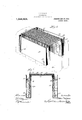
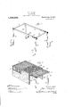
- the evaporating device consists of one or more vessels 10 of flattened elongated rectangular shape adapted to be supported one upon each side of the radiator 11 by means of the-yoke or saddle member shown in Fig. 3.
- the yoke may advantageously consist of a pair of Specification of Letters Patent.
- Fig. 4 is a frag-' Patented Apr. 15,1913.
- transverse members 12, 12 each provided with depending members 13, 13 terminating below in upturned hooks 14, 14, the pair of members connected by longitudinal members .15, 15 secured at the intersection of the transverse and depending members.
- This yoke is adapted to sit astride the radiator 11 and to support within the hooks 14 upon the opposite sides of the radiator the water vessels 10. after the manner of a pair of saddle bags, as shown in Fig. 1.
- the length of the depending members 13, 13 is substantially the same as the height of the vessels 10 and so that the rims of the vessels occupy substantially thesame horizontal plane as the transverse members 12.
- a foraminous plate 16 advantageously formed of Woven wire cloth reinforced by a marginal binding 17 the sides of which are preferably downwardly turned to confine the same upon the yoke whereby to form a shelf extending laterally between the rims of the vessels, as shown in Flgs. 2' and 4:.
- An absorbent sheet 18 of a suitable fabric and preferably wool felt has its medial portion provided with a plurality of perforations 19 by means of a die or any other suitable manner while the end portions 20, 20-are preferably imperforate and of such texture as to facilitate transmlsslon of water by capillary action.
- Thissheet 1s so dis posed with its medlal perforate portlon upon the shelf 16 that the imperforate portions 20, 20 depend one within each of the vessels 10, 10 extending substantially to the bottom thereof.
- cover plate 21 likewise advantageously formed of woven wire cloth marginally reinforced by abinding 22 and bent downwardly alon its two sides w1th1n the upper portion of the vessels 10, 10 to overlie and securely hold in place upon the shelf and 'within the vessels the sheet 18.
- the vessels 10 having been filled with water, as indicated in Fig. 2, the water is by the capillary action of the fabric 18 carried upward and laterally from both sides so as to maintain the medial perforate portion of the sheet in a saturated condition.
- the heated air arising from the radiator passes freely through the foraminous shelf 16, the perforated sheet 18, and the foramlnous cover 21 evaporating the water in the saturated .sheet whereby such air .is prop-' erly charged with water vapor.
- a device thus constructed is comparatively inexpensive to manufacture and by reason of the facility with which the parts may be disassembled and assembled the absorbent sheet can be readily removed for renewal or cleansing, the vessels 10 may be filled without removal, or they may be readily detached if desired for cleansing, the removal of sediment, etc. 1
- Figs. 5 and 6 I have shown a modified form. of the invention wherein a single water vessel 23 is employed having formed rigidly therewith a skeleton shelf 24: extending laterally from the rim thereof and supporting the foraminous plate 25 of'suitably bound woven wire.
- the water vessel 23 is suspended fromthe radiator 26 by means of a pair-of books 27, 27 pivotally connected to the rear face of thevessel 23 by the ears 28, 28.
- a sheet of felt is employed having its lower portion 29 depending below the surface of the wa- "ter in the vessel 23 while its upper perfoby the heated air arising from the radiator.
- a water supply vessel means to Support the. same'ad acenta radiator, a sheet of felt dissupported upon one side of the radiator with the foraminous shelf and perforated sheet'ove'rhanging the sameand traversed I -claim 1.
- a water supply vessel adapted'to be supported adjacent a radiator, and a sheet of perforated absorbentmaterial of close texturevdispos'ed within the vesseland extending therefrom in the path. of the heated air currents, substantially as described.
- a water supply vessel means to support the same adjacent a radiator, and a sheet of Wool felt having an imperforate portion disposed within the vessel and a perforated portion extending therefrom laterally, and means to support such lateral extension across the path of the ascending heated air currents, substantially as described.
- a yoke adapted to overlie the radiator, a pair of water vessels supported by the'yoke one on each side of the radiator, a foraminous shelf extending betweenthe rims of the vessels above the radiator, and a sheet of absorbent material having its ends disposed within the two vessels and a medial permeable portion supported on the foraminous shelf above the radiator, substantially as I described.
- a yoke adapted to overlie the radiator, a-
- a .sheet of absorbent material having its ends disposed within the two vessels and its medial portion supported on the foraminous shelf, the medial portion of the sheet provided with openings to permit the passage of air therethrough, substantially as .described.
- a yoke adaptedto overlie the radiator, a
- a yoke adapted to overlie the radiator and provided-with dependent hooks, a pair of water vessels supported within the hooks of the yoke one on each side of the radiator, a foraminous shelf extending between the rims of the vessels above the radiator and supported by a yoke, and a continuous sheet of felt having its end portions imperforate and disposed within the two vessels and its medial portion perforated and su ported on the foraminous shelf and a oraminous cover sheet overlying the felt on shelf, substantially as described.
Landscapes
- Engineering & Computer Science (AREA)
- Physics & Mathematics (AREA)
- Thermal Sciences (AREA)
- Chemical & Material Sciences (AREA)
- Combustion & Propulsion (AREA)
- Mechanical Engineering (AREA)
- General Engineering & Computer Science (AREA)
- Nonwoven Fabrics (AREA)
Description
P. THILGES.
EVAPORATOR.
APPLICATION 'IILE'D MAY 10, 1912.
Patented Apr. 15, 1913.
3 SHEETS-SHEET 1.
P. THILGES.
EVAPORATOR APPLICATION FILED MAY 10, 1912.
Patented Apr. 15, 1913.
3 RHEBTSSHEET 2.
P. THILGBS.
EVAPORATOR.
APPLICATION FILED MAY 10,1912.
3 & m :3 5H 4 RS pm lllllllllll 1| Mm 2 m 3 MW ma w mi EVA D... Q m
: l u 8 0 6 8 e 5 8 6 5 6 0 E 1 a UNITED sTAtias PATENT OFFICE.
PETER THILG-ES, OF KENOSHA, WISCONSIN, ASSIGNOR TO THE SIMMONSMANUFAC- TUBING OOMPANY,-OF KENOSHA, WISCONSIN, A CORPORATION WISCONSIN.
EVAPORATOR.
To all whom it may concern.
Be it known that 1, PETER THILGES, a citizen of the United States, residing at Kenosha, in the county of Kenosha and State of Wisconsin, have invented new and useful Improvements in Evaporators, of which the following is a specification.
My invention pertains to improvements in humidors or evaporators employed to charge with water vapor the air from heated radiators, uslng the term radiator in a generic sense, whereby to humidify the air of heated sightliness of the device as well as itsefiiciency for the purposes intended.
The invention as thus' outlined will be fully understood from the following detail description of a preferred embodiment and a modified embodiment of the same based upon the accompanying.illustrative drawings, wherein:
form of radiator. Fig. 2 is a vertical transd Figure l is a eperspective view of the evaporator shown In assembled relation to one foraminous plates supported by said yoke.
Fig. 5 is a perspective view of a 'modified form of evaporator, and Fig. 6 is. a vertical transverse section through the form of the device shown in Fig. 5.
Referring to the drawings and more particularly to Figs. 1 to 4 thereofthe evaporating device consists of one or more vessels 10 of flattened elongated rectangular shape adapted to be supported one upon each side of the radiator 11 by means of the-yoke or saddle member shown in Fig. 3. The yoke -may advantageously consist of a pair of Specification of Letters Patent.
Application filed May 10, 1912. Serial No. 696,300.
Fig. 4 is a frag-' Patented Apr. 15,1913.
transverse members 12, 12 each provided with depending members 13, 13 terminating below in upturned hooks 14, 14, the pair of members connected by longitudinal members .15, 15 secured at the intersection of the transverse and depending members. This yoke is adapted to sit astride the radiator 11 and to support within the hooks 14 upon the opposite sides of the radiator the water vessels 10. after the manner of a pair of saddle bags, as shown in Fig. 1. The length of the depending members 13, 13 is substantially the same as the height of the vessels 10 and so that the rims of the vessels occupy substantially thesame horizontal plane as the transverse members 12.
Supported upon the transverse members 12 is a foraminous plate 16 advantageously formed of Woven wire cloth reinforced by a marginal binding 17 the sides of which are preferably downwardly turned to confine the same upon the yoke whereby to form a shelf extending laterally between the rims of the vessels, as shown in Flgs. 2' and 4:. An absorbent sheet 18 of a suitable fabric and preferably wool felt has its medial portion provided with a plurality of perforations 19 by means of a die or any other suitable manner while the end portions 20, 20-are preferably imperforate and of such texture as to facilitate transmlsslon of water by capillary action. Thissheet 1s so dis posed with its medlal perforate portlon upon the shelf 16 that the imperforate portions 20, 20 depend one within each of the vessels 10, 10 extending substantially to the bottom thereof. Above the shelf and upon the absorbent sheet 18 is disposed a foraminous.
The vessels 10 having been filled with water, as indicated in Fig. 2, the water is by the capillary action of the fabric 18 carried upward and laterally from both sides so as to maintain the medial perforate portion of the sheet in a saturated condition. The heated air arising from the radiator passes freely through the foraminous shelf 16, the perforated sheet 18, and the foramlnous cover 21 evaporating the water in the saturated .sheet whereby such air .is prop-' erly charged with water vapor.
It will be readily understood that a device thus constructed is comparatively inexpensive to manufacture and by reason of the facility with which the parts may be disassembled and assembled the absorbent sheet can be readily removed for renewal or cleansing, the vessels 10 may be filled without removal, or they may be readily detached if desired for cleansing, the removal of sediment, etc. 1
I have discovered that while other forms of absorbent sheets may be used in a device of this character if properly divided to permit the passage therethrough of the heated air, yet perforated felt possesses many advantages over other absorbent fabrics because of the uniformity with which the wa 2O ter is carried by capillary action therein and the facility with which the .water is evaporated from the belt by the heated air passing therethrough.
In Figs. 5 and 6 I have shown a modified form. of the invention whereina single water vessel 23 is employed having formed rigidly therewith a skeleton shelf 24: extending laterally from the rim thereof and supporting the foraminous plate 25 of'suitably bound woven wire. In this form of the invention the water vessel 23 is suspended fromthe radiator 26 by means of a pair-of books 27, 27 pivotally connected to the rear face of thevessel 23 by the ears 28, 28. In
this embodiment, as in the-other, a sheet of felt is employed having its lower portion 29 depending below the surface of the wa- "ter in the vessel 23 while its upper perfoby the heated air arising from the radiator.
, a water supply vessel, means to Support the. same'ad acenta radiator, a sheet of felt dissupported upon one side of the radiator with the foraminous shelf and perforated sheet'ove'rhanging the sameand traversed I -claim 1. In a device of the character described,
a water supply vessel adapted'to be supported adjacent a radiator, and a sheet of perforated absorbentmaterial of close texturevdispos'ed within the vesseland extending therefrom in the path. of the heated air currents, substantially as described.
2. In a device of the character described,
posed'within the vessel and having a perforated portlon extending therefrom and exposed to the heat from the radiator, sub- 'stantiallyja's' described. a
3. a device of thecharacter described,
a water supply vessel, means to support the same adjacent a radiator, and a sheet of Wool felt having an imperforate portion disposed within the vessel and a perforated portion extending therefrom laterally, and means to support such lateral extension across the path of the ascending heated air currents, substantially as described.
4:. In a device of the character described, a yoke adapted to overlie the radiator, a pair of water vessels supported by the'yoke one on each side of the radiator, a foraminous shelf extending betweenthe rims of the vessels above the radiator, and a sheet of absorbent material having its ends disposed within the two vessels and a medial permeable portion supported on the foraminous shelf above the radiator, substantially as I described.
5. In a device of the character described,
a yoke adapted to overlie the radiator, a-
the vessels and above the radiator, and a .sheet of absorbent material having its ends disposed within the two vessels and its medial portion supported on the foraminous shelf, the medial portion of the sheet provided with openings to permit the passage of air therethrough, substantially as .described.
6. In a device of the character described, a yoke adaptedto overlie the radiator, a
pair of water vessels supported by the yoke on each side of the radiator, a foraminous shelf extending between the rims of the vessel above the radiator and supported by the yoke, and a continuous sheet of felt having its ends disposed within the two vessels and its medial portion supported on the foraminous shelf, the medial portion of the sheet provided with openings to permit the passage of air therethrough, substantially as described.
7 In a device of the character described, a yoke adapted to overlie the radiator and provided-with dependent hooks, a pair of water vessels supported within the hooks of the yoke one on each side of the radiator, a foraminous shelf extending between the rims of the vessels above the radiator and supported by a yoke, and a continuous sheet of felt having its end portions imperforate and disposed within the two vessels and its medial portion perforated and su ported on the foraminous shelf and a oraminous cover sheet overlying the felt on shelf, substantially as described.
.PETER-THILGES. Witnesses:
WM. W. VINCENT, A. R. DANIELS.
Priority Applications (1)
| Application Number | Priority Date | Filing Date | Title |
|---|---|---|---|
| US69630012A US1058808A (en) | 1912-05-10 | 1912-05-10 | Evaporator. |
Applications Claiming Priority (1)
| Application Number | Priority Date | Filing Date | Title |
|---|---|---|---|
| US69630012A US1058808A (en) | 1912-05-10 | 1912-05-10 | Evaporator. |
Publications (1)
| Publication Number | Publication Date |
|---|---|
| US1058808A true US1058808A (en) | 1913-04-15 |
Family
ID=3127061
Family Applications (1)
| Application Number | Title | Priority Date | Filing Date |
|---|---|---|---|
| US69630012A Expired - Lifetime US1058808A (en) | 1912-05-10 | 1912-05-10 | Evaporator. |
Country Status (1)
| Country | Link |
|---|---|
| US (1) | US1058808A (en) |
Cited By (9)
| Publication number | Priority date | Publication date | Assignee | Title |
|---|---|---|---|---|
| US2651293A (en) * | 1949-03-16 | 1953-09-08 | Skuttle Mfg Company | Humidifier boiler |
| US2899722A (en) * | 1959-08-18 | Vaporizing device | ||
| US3127106A (en) * | 1964-03-31 | Humidifiers | ||
| US3482929A (en) * | 1964-03-28 | 1969-12-09 | Albert Gentil | Method and apparatus for evaporating volatile solutions of air treatment substances |
| US4388767A (en) * | 1981-03-16 | 1983-06-21 | Dison Gordon F | Process and apparatus for storing paint brushes and the like |
| US5133904A (en) * | 1990-10-17 | 1992-07-28 | Bemis Manufacturing Company | Humidifier |
| US5250232A (en) * | 1990-10-17 | 1993-10-05 | Bemis Manufacturing Company | Humidifier |
| US20040217494A1 (en) * | 2001-12-01 | 2004-11-04 | Lee Man Hi | Natural vaporization humidifier |
| US20100147972A1 (en) * | 2002-10-08 | 2010-06-17 | Lakatos Nee Kotary Kara L | Breakable Wick for Use in a Dispenser for a Volatile Liquid |
-
1912
- 1912-05-10 US US69630012A patent/US1058808A/en not_active Expired - Lifetime
Cited By (11)
| Publication number | Priority date | Publication date | Assignee | Title |
|---|---|---|---|---|
| US2899722A (en) * | 1959-08-18 | Vaporizing device | ||
| US3127106A (en) * | 1964-03-31 | Humidifiers | ||
| US2651293A (en) * | 1949-03-16 | 1953-09-08 | Skuttle Mfg Company | Humidifier boiler |
| US3482929A (en) * | 1964-03-28 | 1969-12-09 | Albert Gentil | Method and apparatus for evaporating volatile solutions of air treatment substances |
| US4388767A (en) * | 1981-03-16 | 1983-06-21 | Dison Gordon F | Process and apparatus for storing paint brushes and the like |
| US5133904A (en) * | 1990-10-17 | 1992-07-28 | Bemis Manufacturing Company | Humidifier |
| US5250232A (en) * | 1990-10-17 | 1993-10-05 | Bemis Manufacturing Company | Humidifier |
| US20040217494A1 (en) * | 2001-12-01 | 2004-11-04 | Lee Man Hi | Natural vaporization humidifier |
| US20050236723A1 (en) * | 2001-12-01 | 2005-10-27 | Lee Man H | Natural vaporization humidifier |
| US20100147972A1 (en) * | 2002-10-08 | 2010-06-17 | Lakatos Nee Kotary Kara L | Breakable Wick for Use in a Dispenser for a Volatile Liquid |
| US8733670B2 (en) | 2002-10-08 | 2014-05-27 | S.C. Johnson & Son, Inc. | Container for holding a volatile material and a wick |
Similar Documents
| Publication | Publication Date | Title |
|---|---|---|
| US1817357A (en) | Humidifier | |
| US1749730A (en) | Filter device | |
| US1628344A (en) | Radiator attachment | |
| US679928A (en) | Tea-kettle attachment. | |
| US504443A (en) | William staab | |
| US447942A (en) | John w | |
| US387236A (en) | Skimmer | |
| US358589A (en) | Wash-boiler | |
| DE688217C (en) | Device for cleaning laundry with an insert base moved by the cooking steam | |
| US365915A (en) | Culinary apparatus | |
| US1049427A (en) | Photographic-print drier. | |
| US1082411A (en) | Evaporating apparatus. | |
| US296743A (en) | Sugar-evaporator | |
| US369713A (en) | Feed-water heater and purifier | |
| US1789213A (en) | Steam board | |
| US432837A (en) | Air-moistening apparatus | |
| US1310705A (en) | Device | |
| US223490A (en) | Carbureter | |
| US1327166A (en) | Apparatus for heating and ripening honey | |
| US57244A (en) | bacon | |
| US1535681A (en) | Device for supplying moisture | |
| US852487A (en) | Feed-water heater and purifier. | |
| SU52506A1 (en) | Device for evaporating deodorizing and disinfecting air substances | |
| US196304A (en) | Improvement in carbureters | |
| US1107379A (en) | Feed-water heater. |