US1058730A - Reversible brush-holder for use with dynamos. - Google Patents
Reversible brush-holder for use with dynamos. Download PDFInfo
- Publication number
- US1058730A US1058730A US64593111A US1911645931A US1058730A US 1058730 A US1058730 A US 1058730A US 64593111 A US64593111 A US 64593111A US 1911645931 A US1911645931 A US 1911645931A US 1058730 A US1058730 A US 1058730A
- Authority
- US
- United States
- Prior art keywords
- brush
- generator
- members
- dynamos
- holders
- Prior art date
- Legal status (The legal status is an assumption and is not a legal conclusion. Google has not performed a legal analysis and makes no representation as to the accuracy of the status listed.)
- Expired - Lifetime
Links
- 230000002441 reversible effect Effects 0.000 title description 7
- LTMHDMANZUZIPE-PUGKRICDSA-N digoxin Chemical compound C1[C@H](O)[C@H](O)[C@@H](C)O[C@H]1O[C@@H]1[C@@H](C)O[C@@H](O[C@@H]2[C@H](O[C@@H](O[C@@H]3C[C@@H]4[C@]([C@@H]5[C@H]([C@]6(CC[C@@H]([C@@]6(C)[C@H](O)C5)C=5COC(=O)C=5)O)CC4)(C)CC3)C[C@@H]2O)C)C[C@@H]1O LTMHDMANZUZIPE-PUGKRICDSA-N 0.000 title description 6
- 238000010276 construction Methods 0.000 description 8
- XEEYBQQBJWHFJM-UHFFFAOYSA-N Iron Chemical compound [Fe] XEEYBQQBJWHFJM-UHFFFAOYSA-N 0.000 description 4
- 238000004804 winding Methods 0.000 description 3
- 238000005266 casting Methods 0.000 description 2
- 229910052742 iron Inorganic materials 0.000 description 2
- 239000000463 material Substances 0.000 description 2
- 229910000906 Bronze Inorganic materials 0.000 description 1
- XAGFODPZIPBFFR-UHFFFAOYSA-N aluminium Chemical compound [Al] XAGFODPZIPBFFR-UHFFFAOYSA-N 0.000 description 1
- 229910052782 aluminium Inorganic materials 0.000 description 1
- 239000010974 bronze Substances 0.000 description 1
- 244000145845 chattering Species 0.000 description 1
- KUNSUQLRTQLHQQ-UHFFFAOYSA-N copper tin Chemical compound [Cu].[Sn] KUNSUQLRTQLHQQ-UHFFFAOYSA-N 0.000 description 1
- 239000000696 magnetic material Substances 0.000 description 1
Images

Classifications
-
- H—ELECTRICITY
- H02—GENERATION; CONVERSION OR DISTRIBUTION OF ELECTRIC POWER
- H02K—DYNAMO-ELECTRIC MACHINES
- H02K23/00—DC commutator motors or generators having mechanical commutator; Universal AC/DC commutator motors
- H02K23/02—DC commutator motors or generators having mechanical commutator; Universal AC/DC commutator motors characterised by arrangement for exciting
- H02K23/18—DC commutator motors or generators having mechanical commutator; Universal AC/DC commutator motors characterised by arrangement for exciting having displaceable main or auxiliary brushes
Definitions
- My invention relates to dynamos or generators and has for its particular object to provide a dynamo wherein the direction of current supplied will remain uniform throughout reversals in direction.
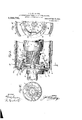
- Figure I is a partial longitudinal section and elevation of one type of generator embodying my invention.
- Fig. H is end section and partial elevation of the generator shown in Fig. I taken on the line
- Fig. III is a partial longitudinal section and elevation of one type of dynamo comprehending my invention
- v Fig. IV is an end section and partial elevation of the dynamo shown in Fig. III taken on the line C-l) on a smaller scale.
- Fig. V is a partial longitudinal section and elevation of a generator comprehending one form of my invention.
- l represents an armature of a generator provided with the usual commutator 2 and carried by the shaft 3.
- 4c is an end casting carrying one of the bearings of the shafts? and preferably provided with a flanged portion 5 carried by the field frame 6 and secured thereto as by screws 7. in Figs. I
- -and II 8 represents a pair of webbed mem here preferably made of bronze, aluminum or some other nonmagnetic material and provided with a bearing portion. journaled upon the shaft 3 and also provided with arms 9 which carry the usual brush-holders 10.
- the parts 8 are preferably held together upon the shaft 3 as by means of springsl'l and are provided at their outer peripheries with a magnetic shoe 12 of iron separated by a narrow air gap from the annular magnet frame 13 containing the exciting winding 14 which may be connected as shown in the drawing in shunt across the brushes carried by the brush-holders 10.
- This annular magnet frame 13 and its winding 14 are permanently secured within the field frame '5;
- brush-holders 10 are rotatable about the shaft 3 and commutator 2 1 and have but little friction thereupon.
- the commutator crushes are slidmgly main-- tained in the brush holders l0 and are each I pressed downward by light spiral springs into contact with the commutator 2,
- the stops 15 are made movable to allow for the width of the arm in each direction so that a full 180 degrees may be given to the brushes upon reversal of rotation or" the armature and thus upon reversal, the brushes will assume positions at the opposite ends of the axis of commutation depending upon the direction of rotation, and in this way the direction of current delivered may be maintained uniform throughout reversals in direction of rotation of the'armature.
- Figs. Ill and IV the end casting l is provided with a hub or extension 17 upon which is fitted an annular ball-bearing member comprising an inner ring 18 and an.
- the entire ball-bearing member may be held in place upon the hub 17 as by the members 21 attached to the hub.
- the members 22 are made of nonmagnetic material and flanged as indicated at 24 to fit loosely upon the outer ring 19, and said members are united as by the springs 11 will be exerted upon in the same direction and will be stopped in the positions indicated in the drawing by the stops 1'5 engaging the arms 9, it being noted that in that construction shown in Fig. I the members 8 will revolve with the shaft 3; in that construction shown in Figs. HI and IV the members 22 will cause the ring 19 to revolve upon the balls 20; in that construction shown in Fig. V the memhers 22 will revolve upon the hub 17. It now the generator speed be raised to that point that the electromotive it'orce of the generator be appreciable, the magnet 13-44:
- a generator comprehending an armature, a commutator, brush holders and rotatable commutator brushes in operative relation therewith; together with electromagnetic means for supporting said brush holders out of mechanical contact with any of the moving parts of the machine.
- A'generator comprehending a commutator, brush holders and commutator brushes in operative relation therewith, rotatable means for holding said brush holders and brushes in operative relation to said commutator, and independent magnetic means for supporting said brush holders out of mechanical contact with any of the moving parts of the machine.
- a generator comprehending a comm;-
- a generator comprehending a rotor, current collecting means in contact therewith, means for supporting said collecting means and allowing motion thereof combined with electromagnetic means for independently supporting said collecting means.
Landscapes
- Engineering & Computer Science (AREA)
- Power Engineering (AREA)
- Motor Or Generator Current Collectors (AREA)
Description
J. L. GREVELING.
REVERSIBLE BRUSH HOLDER FOR USE WITH DYNAMOS.
APPLICATION IILED 111111.25, 1911.
1,058,730. Y Patented Apr. 15,1913.
2 BHEIITSBKEET 1.
WITNESSES J. L. GREVELING. REVERSIBLE BRUSH HOLDER FOR USE WITH DYNAMOS.
APPLICATION FILED mums, 1911.
1,058,730, Patented Apr. 15, 1913.
2 SHEETS-SHEET 2.
/ :QJL
J N N M 3 I 3 l H" I I I i 8 f I g b I r X $2 In Mrl/ I- I $9 g; I x Mi T l f '1 N N i Q Q N x r IIII 1 L I I g 4 I I WITNESSES u; I Y I Qj nwmron UN TED fiillhilldd JQHN 'L. CREVELING, OF NEW YQRRI, IN. e, .ASSIG LIGHTING COMPANY} ,A UGBPOEA'EIGN 0E REVERSIBLE BRUSH ZZfiLEER F81 3, Ufiilrl TO GAR HEATING- All JERSEY.
Specification of Letters Eatent.
Apr, 15, 191$ A nlicatzlon filed .Ltugnst 25, 1311. Serial Ho. 6 55 93. a 3
To all whom it may concern Be it known that I, Jomv L. Csnvnnrue, a resident of New York, in the county and State of New York, have invented certain new and useful Improvements in Reversible Brush-Holders for Use with Dynamos as set forth in the annexed specification and drawings, forming a part thereof.
My invention relates to dynamos or generators and has for its particular object to provide a dynamo wherein the direction of current supplied will remain uniform throughout reversals in direction. of rotation of the armature Figure I is a partial longitudinal section and elevation of one type of generator embodying my invention. Fig. H is end section and partial elevation of the generator shown in Fig. I taken on the line Fig. III is a partial longitudinal section and elevation of one type of dynamo comprehending my invention, v Fig. IV is an end section and partial elevation of the dynamo shown in Fig. III taken on the line C-l) on a smaller scale. Fig. V is a partial longitudinal section and elevation of a generator comprehending one form of my invention.
In the drawing particularly Figs. I and II, l represents an armature of a generator provided with the usual commutator 2 and carried by the shaft 3. 4c is an end casting carrying one of the bearings of the shafts? and preferably provided with a flanged portion 5 carried by the field frame 6 and secured thereto as by screws 7. in Figs. I
-and II 8 represents a pair of webbed mem here preferably made of bronze, aluminum or some other nonmagnetic material and provided with a bearing portion. journaled upon the shaft 3 and also provided with arms 9 which carry the usual brush-holders 10. The parts 8 are preferably held together upon the shaft 3 as by means of springsl'l and are provided at their outer peripheries with a magnetic shoe 12 of iron separated by a narrow air gap from the annular magnet frame 13 containing the exciting winding 14 which may be connected as shown in the drawing in shunt across the brushes carried by the brush-holders 10. This annular magnet frame 13 and its winding 14 are permanently secured within the field frame '5;
While the members 8, integral brush carrymg arms 9. brush-holders 10 are rotatable about the shaft 3 and commutator 2 1 and have but little friction thereupon. The commutator crushes are slidmgly main-- tained in the brush holders l0 and are each I pressed downward by light spiral springs into contact with the commutator 2,
clearly shown in I, III and V of the drawings. 15 is a stop, or limiting device, carried by the screws 16 in such manner as to engage the arms 9 andv prevent rotation of the brushes and members 8 with the armature beyond certain desired limits which in the present instance, inasmuch as a bipolar machine is indicated for sake of sim plicity is substantially degrees, and it will be noted that the stops 15 are made movable to allow for the width of the arm in each direction so that a full 180 degrees may be given to the brushes upon reversal of rotation or" the armature and thus upon reversal, the brushes will assume positions at the opposite ends of the axis of commutation depending upon the direction of rotation, and in this way the direction of current delivered may be maintained uniform throughout reversals in direction of rotation of the'armature.
In Figs. Ill and IV the end casting l is provided with a hub or extension 17 upon which is fitted an annular ball-bearing member comprising an inner ring 18 and an.
outer ring 19 both forming a ball-race containing the balls 20. The entire ball-bearing membermay be held in place upon the hub 17 as by the members 21 attached to the hub. The members 22 are made of nonmagnetic material and flanged as indicated at 24 to fit loosely upon the outer ring 19, and said members are united as by the springs 11 will be exerted upon in the same direction and will be stopped in the positions indicated in the drawing by the stops 1'5 engaging the arms 9, it being noted that in that construction shown in Fig. I the members 8 will revolve with the shaft 3; in that construction shown in Figs. HI and IV the members 22 will cause the ring 19 to revolve upon the balls 20; in that construction shown in Fig. V the memhers 22 will revolve upon the hub 17. It now the generator speed be raised to that point that the electromotive it'orce of the generator be appreciable, the magnet 13-44:
will become energized due to the current in the winding 14 and the shoes 12 will be attracted and firmly held within the annular magnet and all frictional contact between the members 8 and any revolving parts of the generator will be broken-that is, in the construction shown in .Fig. I the members 8 will be lifted clear of the shaft 3 and no wear will take place due to revolution of the shaft; in that construction shown in Figs. III and IV the members 22 will be lifted clear of the ring 19 and no pressure the balls or ball-races; in that construction shown in Fig. V the members 22 will be lifted clear 17 and firmly held within the magnet 13-1n It will be noted that with this construction, when the generator is in operation, the brush rigging will be supported by the electromagnets and these are provided with complete magnetic circuits of iron, or other magnetic material, and, therefore, the tractive force is very great and the brush-holders are firmly held in their proper positions. If now the generator stop, the magnets will release the shoes 12 and the brush rigging will assume the positions shown in the drawings. If the direct-ion of rotation of the armature be changed, the members 8 of the generator shown in Figs. I and H together with the brush rigging therefor will revolve into a reverse position placing the brushes at opposite ends or" the axis of commutation and thus compensate for said reversal of rotation. If now the generator voltage rise, the magnet 13-14= will again attract the shoes and lift the supporting members clear of the moving parts of the generator and the brush rigging will again be held in its proper definite relation. by means of the magnetic clutches.
the ine. it will. be obvious that posed upon any or" the hub s eaves when my generator is running at such speed as to be useful, all strain upon the brushes and brush-holders will be carried by the magnetic brush-holder supports and not imof the members upon-which the brush rigging revolves in performing its function of rectifying the polarity of the machine; therefore, chattering or vibration of the brushes due to uneven wear of the commutator will not tend to injure the hearing members and the brush rigging may be carried by loose bearing members so as to be free to revolve readily, as the said bearing members do not have imposed upon them the function of holding the brush rigging' in its proper operating relation when the generator is running.
I do notwish in any way to limit myself to any of the details of construction or to the exact mode of operation set forth in this application which are given to illustrate types of dynamos comprehending the essentials of my invention.
1 make no claim in the present application broadly to rotatable reversible means for maintaining the polarity of the current the same on reversal of the rotation of the armature of a dynamo electric machine in combination with means for stopping the rotation of such pole changing means at the limit of their rotation, together with means for additionally firmly holding the same after the armature has reached its proper speed of rotation, as this constitutes the subject matter of an earlier application filed by me in the U. S. Patent Otfice on the 7th day 01 August, 1911 and bearing Serial No. 642,582.
It will be obvious that wide departure in the way of details may be made without departing from the spirit and scope of my invent-ion which is as set forth in the following claims.
It claims-- 1. A generator comprehending an armature, a commutator, brush holders and rotatable commutator brushes in operative relation therewith; together with electromagnetic means for supporting said brush holders out of mechanical contact with any of the moving parts of the machine.
2. A'generator comprehending a commutator, brush holders and commutator brushes in operative relation therewith, rotatable means for holding said brush holders and brushes in operative relation to said commutator, and independent magnetic means for supporting said brush holders out of mechanical contact with any of the moving parts of the machine.
3. A generator comprehending a comm;-
tator brush holders and commutator brushes 1n operative relation therewith, rotatable means for carrying said brush holders and brush and p mitting movement of the same, and electromagnetic means for iifde; pendently supporting said brush holders out of mechanical contact With any of the moving parts of the machine.
4:. A generator comprehending a rotor, current collecting means in contact therewith, means for supporting said collecting means and allowing motion thereof combined with electromagnetic means for independently supporting said collecting means.
' JOHN L. GREVELING. Witnesses:
M. HERSKOVITZ, M. HILLOGK.
Priority Applications (1)
| Application Number | Priority Date | Filing Date | Title |
|---|---|---|---|
| US64593111A US1058730A (en) | 1911-08-25 | 1911-08-25 | Reversible brush-holder for use with dynamos. |
Applications Claiming Priority (1)
| Application Number | Priority Date | Filing Date | Title |
|---|---|---|---|
| US64593111A US1058730A (en) | 1911-08-25 | 1911-08-25 | Reversible brush-holder for use with dynamos. |
Publications (1)
| Publication Number | Publication Date |
|---|---|
| US1058730A true US1058730A (en) | 1913-04-15 |
Family
ID=3126983
Family Applications (1)
| Application Number | Title | Priority Date | Filing Date |
|---|---|---|---|
| US64593111A Expired - Lifetime US1058730A (en) | 1911-08-25 | 1911-08-25 | Reversible brush-holder for use with dynamos. |
Country Status (1)
| Country | Link |
|---|---|
| US (1) | US1058730A (en) |
-
1911
- 1911-08-25 US US64593111A patent/US1058730A/en not_active Expired - Lifetime
Similar Documents
| Publication | Publication Date | Title |
|---|---|---|
| US2484197A (en) | Wind-driven electric power plant | |
| US2378668A (en) | Electrical machine | |
| JP2016116407A (en) | Rotary electric machine | |
| US20250112529A1 (en) | Rotating brushes for electric motors | |
| US586823A (en) | Francis jarvis patten | |
| US1131614A (en) | Electric motor. | |
| US1212476A (en) | Dynamo. | |
| CN203406758U (en) | A permanent magnet DC motor | |
| US1893629A (en) | Electric motor | |
| US742600A (en) | Dynamo-electric machine or motor. | |
| US2511412A (en) | Motor generator | |
| CN105978213A (en) | Magnetic fluid suspension bearing of disc motor | |
| US1251645A (en) | Reversible brush-holder for use with dynamos. | |
| US1253157A (en) | Reversible brush-holder for use with dynamos. | |
| US616396A (en) | Combined bearing and power-transmitting device | |
| US1276726A (en) | Brush-holder for dynamos. | |
| US1109901A (en) | Reversible brush-holder for dynamos. | |
| US1276727A (en) | Reversible brush-holder for use with dynamos. | |
| US399800A (en) | Dynamo-electric machine | |
| GB1148304A (en) | Dynamo electric machines | |
| US1019709A (en) | Electric motor and dynamo. | |
| US1079008A (en) | Dynamo-electric generator. | |
| US1638890A (en) | Dynamo-electric machine | |
| US1164262A (en) | Reversible brush-holder for dynamo-electric machines. | |
| US411833A (en) | Electric motor |