US10587080B2 - Connector, connector assembly and lighting system - Google Patents
Connector, connector assembly and lighting system Download PDFInfo
- Publication number
- US10587080B2 US10587080B2 US16/295,209 US201916295209A US10587080B2 US 10587080 B2 US10587080 B2 US 10587080B2 US 201916295209 A US201916295209 A US 201916295209A US 10587080 B2 US10587080 B2 US 10587080B2
- Authority
- US
- United States
- Prior art keywords
- mounting member
- connector
- coupled
- connection element
- mating
- Prior art date
- Legal status (The legal status is an assumption and is not a legal conclusion. Google has not performed a legal analysis and makes no representation as to the accuracy of the status listed.)
- Active
Links
Images


Classifications
-
- F—MECHANICAL ENGINEERING; LIGHTING; HEATING; WEAPONS; BLASTING
- F21—LIGHTING
- F21V—FUNCTIONAL FEATURES OR DETAILS OF LIGHTING DEVICES OR SYSTEMS THEREOF; STRUCTURAL COMBINATIONS OF LIGHTING DEVICES WITH OTHER ARTICLES, NOT OTHERWISE PROVIDED FOR
- F21V21/00—Supporting, suspending, or attaching arrangements for lighting devices; Hand grips
- F21V21/005—Supporting, suspending, or attaching arrangements for lighting devices; Hand grips for several lighting devices in an end-to-end arrangement, i.e. light tracks
-
- F—MECHANICAL ENGINEERING; LIGHTING; HEATING; WEAPONS; BLASTING
- F21—LIGHTING
- F21V—FUNCTIONAL FEATURES OR DETAILS OF LIGHTING DEVICES OR SYSTEMS THEREOF; STRUCTURAL COMBINATIONS OF LIGHTING DEVICES WITH OTHER ARTICLES, NOT OTHERWISE PROVIDED FOR
- F21V23/00—Arrangement of electric circuit elements in or on lighting devices
- F21V23/06—Arrangement of electric circuit elements in or on lighting devices the elements being coupling devices, e.g. connectors
-
- H—ELECTRICITY
- H01—ELECTRIC ELEMENTS
- H01R—ELECTRICALLY-CONDUCTIVE CONNECTIONS; STRUCTURAL ASSOCIATIONS OF A PLURALITY OF MUTUALLY-INSULATED ELECTRICAL CONNECTING ELEMENTS; COUPLING DEVICES; CURRENT COLLECTORS
- H01R13/00—Details of coupling devices of the kinds covered by groups H01R12/70 or H01R24/00 - H01R33/00
- H01R13/46—Bases; Cases
- H01R13/52—Dustproof, splashproof, drip-proof, waterproof, or flameproof cases
- H01R13/5202—Sealing means between parts of housing or between housing part and a wall, e.g. sealing rings
-
- H—ELECTRICITY
- H01—ELECTRIC ELEMENTS
- H01R—ELECTRICALLY-CONDUCTIVE CONNECTIONS; STRUCTURAL ASSOCIATIONS OF A PLURALITY OF MUTUALLY-INSULATED ELECTRICAL CONNECTING ELEMENTS; COUPLING DEVICES; CURRENT COLLECTORS
- H01R13/00—Details of coupling devices of the kinds covered by groups H01R12/70 or H01R24/00 - H01R33/00
- H01R13/46—Bases; Cases
- H01R13/52—Dustproof, splashproof, drip-proof, waterproof, or flameproof cases
- H01R13/5205—Sealing means between cable and housing, e.g. grommet
-
- H—ELECTRICITY
- H01—ELECTRIC ELEMENTS
- H01R—ELECTRICALLY-CONDUCTIVE CONNECTIONS; STRUCTURAL ASSOCIATIONS OF A PLURALITY OF MUTUALLY-INSULATED ELECTRICAL CONNECTING ELEMENTS; COUPLING DEVICES; CURRENT COLLECTORS
- H01R13/00—Details of coupling devices of the kinds covered by groups H01R12/70 or H01R24/00 - H01R33/00
- H01R13/46—Bases; Cases
- H01R13/52—Dustproof, splashproof, drip-proof, waterproof, or flameproof cases
- H01R13/5216—Dustproof, splashproof, drip-proof, waterproof, or flameproof cases characterised by the sealing material, e.g. gels or resins
-
- H—ELECTRICITY
- H01—ELECTRIC ELEMENTS
- H01R—ELECTRICALLY-CONDUCTIVE CONNECTIONS; STRUCTURAL ASSOCIATIONS OF A PLURALITY OF MUTUALLY-INSULATED ELECTRICAL CONNECTING ELEMENTS; COUPLING DEVICES; CURRENT COLLECTORS
- H01R13/00—Details of coupling devices of the kinds covered by groups H01R12/70 or H01R24/00 - H01R33/00
- H01R13/58—Means for relieving strain on wire connection, e.g. cord grip, for avoiding loosening of connections between wires and terminals within a coupling device terminating a cable
- H01R13/5804—Means for relieving strain on wire connection, e.g. cord grip, for avoiding loosening of connections between wires and terminals within a coupling device terminating a cable comprising a separate cable clamping part
- H01R13/5816—Means for relieving strain on wire connection, e.g. cord grip, for avoiding loosening of connections between wires and terminals within a coupling device terminating a cable comprising a separate cable clamping part for cables passing through an aperture in a housing wall, the separate part being captured between cable and contour of aperture
-
- H—ELECTRICITY
- H01—ELECTRIC ELEMENTS
- H01R—ELECTRICALLY-CONDUCTIVE CONNECTIONS; STRUCTURAL ASSOCIATIONS OF A PLURALITY OF MUTUALLY-INSULATED ELECTRICAL CONNECTING ELEMENTS; COUPLING DEVICES; CURRENT COLLECTORS
- H01R13/00—Details of coupling devices of the kinds covered by groups H01R12/70 or H01R24/00 - H01R33/00
- H01R13/62—Means for facilitating engagement or disengagement of coupling parts or for holding them in engagement
- H01R13/629—Additional means for facilitating engagement or disengagement of coupling parts, e.g. aligning or guiding means, levers, gas pressure electrical locking indicators, manufacturing tolerances
- H01R13/631—Additional means for facilitating engagement or disengagement of coupling parts, e.g. aligning or guiding means, levers, gas pressure electrical locking indicators, manufacturing tolerances for engagement only
- H01R13/6315—Additional means for facilitating engagement or disengagement of coupling parts, e.g. aligning or guiding means, levers, gas pressure electrical locking indicators, manufacturing tolerances for engagement only allowing relative movement between coupling parts, e.g. floating connection
-
- H—ELECTRICITY
- H01—ELECTRIC ELEMENTS
- H01R—ELECTRICALLY-CONDUCTIVE CONNECTIONS; STRUCTURAL ASSOCIATIONS OF A PLURALITY OF MUTUALLY-INSULATED ELECTRICAL CONNECTING ELEMENTS; COUPLING DEVICES; CURRENT COLLECTORS
- H01R13/00—Details of coupling devices of the kinds covered by groups H01R12/70 or H01R24/00 - H01R33/00
- H01R13/73—Means for mounting coupling parts to apparatus or structures, e.g. to a wall
-
- H—ELECTRICITY
- H01—ELECTRIC ELEMENTS
- H01R—ELECTRICALLY-CONDUCTIVE CONNECTIONS; STRUCTURAL ASSOCIATIONS OF A PLURALITY OF MUTUALLY-INSULATED ELECTRICAL CONNECTING ELEMENTS; COUPLING DEVICES; CURRENT COLLECTORS
- H01R24/00—Two-part coupling devices, or either of their cooperating parts, characterised by their overall structure
-
- F—MECHANICAL ENGINEERING; LIGHTING; HEATING; WEAPONS; BLASTING
- F21—LIGHTING
- F21Y—INDEXING SCHEME ASSOCIATED WITH SUBCLASSES F21K, F21L, F21S and F21V, RELATING TO THE FORM OR THE KIND OF THE LIGHT SOURCES OR OF THE COLOUR OF THE LIGHT EMITTED
- F21Y2103/00—Elongate light sources, e.g. fluorescent tubes
-
- F—MECHANICAL ENGINEERING; LIGHTING; HEATING; WEAPONS; BLASTING
- F21—LIGHTING
- F21Y—INDEXING SCHEME ASSOCIATED WITH SUBCLASSES F21K, F21L, F21S and F21V, RELATING TO THE FORM OR THE KIND OF THE LIGHT SOURCES OR OF THE COLOUR OF THE LIGHT EMITTED
- F21Y2115/00—Light-generating elements of semiconductor light sources
- F21Y2115/10—Light-emitting diodes [LED]
-
- H—ELECTRICITY
- H01—ELECTRIC ELEMENTS
- H01R—ELECTRICALLY-CONDUCTIVE CONNECTIONS; STRUCTURAL ASSOCIATIONS OF A PLURALITY OF MUTUALLY-INSULATED ELECTRICAL CONNECTING ELEMENTS; COUPLING DEVICES; CURRENT COLLECTORS
- H01R13/00—Details of coupling devices of the kinds covered by groups H01R12/70 or H01R24/00 - H01R33/00
- H01R13/62—Means for facilitating engagement or disengagement of coupling parts or for holding them in engagement
- H01R13/639—Additional means for holding or locking coupling parts together, after engagement, e.g. separate keylock, retainer strap
Definitions
- Embodiments of the present disclosure relate generally to a connector assembly, and more particularly relate to a connector assembly for use in lighting field.
- Connector assemblies comprising at least one connector are widely used in a multitude of fields.
- connectors are used to connect illumination elements or used to connect illumination elements to a power source.
- huge stress between connectors will cause failures like overheat, overload, burnout at the connectors and poor contacts between conductors of the connectors.
- the huge stress between connectors is caused by the thermal expansion & contraction of the illumination elements and/or difficult to align the illumination elements in a straight line by mounting clips.
- the illumination elements are connected using cable to board connector assemblies or cable to cable connector assemblies which can avoid the stress between connectors.
- the connector assemblies with cables may need more space between connectors, and the cables may be exposed and thus look not neat.
- a connector is provided to be assembled on a first illumination element and to be releasably coupled to a mating connector on a second illumination element.
- the connector includes a connection element comprising a conductor, the conductor including a first end coupled to a cable extending through the connection element, and a second end releasably connected to an end of a mating conductor of the mating connector; a mounting member configured to secure the connection element to the first illumination element, wherein, a first gap is defined between an internal surface of the mounting member and the external surface of the connection element; a first sealing element coupled to the mounting member and the connection element, and configured to seal the first gap around a first longitudinal end of the mounting member; a second sealing element coupled to the mounting member and the cable, and configured to seal a second gap between a second longitudinal end of the mounting member and the cable; and wherein an inner cavity is formed among the mounting member, the connection element, the first sealing element and the second sealing element, and at least a part of the
- a connector assembly includes a connector configured to be assembled on a first illumination element and a mating connector configured to be assembled on a second illumination and to be releasably coupled to the connector.
- the connector includes a connection element including a conductor, the conductor comprising a first end coupled to a cable extending through the connection element, and a second end releasably connected to an end of a mating conductor of the mating connector; a mounting member configured to secure the connection element to the first illumination element, a first gap is defined between an internal surface of the mounting member and the external surface of the connection element; a first sealing element coupled to the mounting member and the connection element, and configured to seal the first gap around a first longitudinal end of the mounting member; a second sealing element coupled to the mounting member and the cable, and configured to seal a second gap between a second longitudinal end of the mounting member and the cable; and an inner cavity is formed among the mounting member, the connection element, the first sealing element and the second sealing element, and at least
- a lighting system includes at least two illumination elements, and at least one longitudinal end of the illumination element is coupled with a connector for engaging a mating connector on a power source or another illumination element.
- the connector includes a connection element including a conductor, the conductor comprising a first end coupled to a cable extending through the connection element, and a second end releasably connected to an end of a mating conductor of the mating connector; a mounting member configured to secure the connection element to the first illumination element, wherein, a first gap is defined between an internal surface of the mounting member and the external surface of the connection element; a first sealing element coupled to the mounting member and the connection element, and configured to seal the first gap around a first longitudinal end of the mounting member; a second sealing element coupled to the mounting member and the cable, and configured to seal a second gap between a second longitudinal end of the mounting member and the cable; and an inner cavity is formed among the mounting member, the connection element, the first sealing element and the second sealing element, and at least a part
- FIG. 1 is a perspective view of a connector assembly in accordance with aspects described herein;
- FIG. 2 is a cross-sectional view of the connector assembly of FIG. 1 in connecting with a first and second illumination element, in accordance with aspects described herein;
- FIG. 3 is a partial enlarged view of the portion encircled in FIG. 2 , showing a gap between a connector and a mounting member;
- FIG. 4 is an end view of a connector for using in the connector assembly of FIG. 1 in accordance with aspects described herein;
- FIG. 5 is an end view of a mating connector for using in the connector assembly of FIG. 1 in accordance with aspects described herein;
- FIG. 6 is a front view of a lighting system using the connector assembly of FIG. 1 in accordance with aspects described herein;
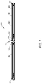
- FIG. 7 is a cross-section view taken along the line 6 - 6 of FIG. 6 .
- ком ⁇ онент is generally intended to refer to a computer-related entity, either hardware, a combination of hardware and software, software, or software in execution.
- a component may be, but is not limited to being, a process running on a processor, a processor, an object, an executable, a thread of execution, a program, and/or a computer.
- FIG. 1 is a perspective view of a connector assembly 10 .
- FIG. 2 is a cross-sectional view of the connector assembly 10 of FIG. 1 , in connecting with a first illumination element 16 and a second illumination element 18 .
- the connector assembly 10 includes a connector 12 and a mating connector 14 .
- the connector 12 on the first illumination element 16 is configured to be releasably coupled to the mating connector 14 on the second illumination element 18 .
- the connector 12 includes a connection element 121 , a mounting member 122 , a first sealing element 123 and a second sealing element 124 .
- the connection element 121 includes a conductor 126 , the conductor 126 includes a first end 127 coupled and electrically connected to a cable 129 extending through the connection element 121 , and a second end 128 releasably connected to an end 147 of a mating conductor 146 of the mating connector 14 .
- the cable 129 is located inside the first illumination elements 16 .
- the connection element 121 includes two conductors 126 .
- the number of the conductor 126 is not limited herein, and in some embodiments, the number may be greater than 2, such as 3, 4, 5 etc.
- the mounting member 122 is configured to secure the connection element 121 to the first illumination element 16 , further refer to FIG. 3 , wherein, a first gap 130 is defined between an internal surface of the mounting member 122 and an external surface of the connection element 121 .
- the first gap 130 is from about 0.5 millimeters to about 10 millimeters in a radial direction. In some specific embodiments, the gap 130 is from about 0.5 millimeters to about 1 millimeter in a radial direction.
- the mounting member 122 includes a substantially hollow cylinder 131 and a securing element 132 coupled to one longitudinal end of the substantially hollow cylinder 131 .
- the other end of the substantially hollow cylinder 131 is accommodated in the first illumination element 16 .
- the external diameter of the substantially hollow cylinder 131 is determined based on the design of the first illumination element 16 .
- the securing element 132 is configured to couple and fix the connection element 121 to the first illumination element 16 .
- the substantially hollow cylinder 131 and the securing element 132 is formed integrally.
- the mounting member 122 is an endcap coupled on the first illumination element 16 .
- connection element 121 has a substantially cylindrical structure, and the first gap 130 is defined between the internal surface of the mounting member 122 and the external surface of the substantially cylindrical structure of the connection element 121 .
- the first sealing element 123 is coupled to the mounting member 122 and the connection element 121 , and configured to seal the first gap 130 around a first longitudinal end of the mounting member 122 .
- the first sealing element 123 can prevent rain or other contaminants from entering the connector 12 and/or the first illumination element 16 .
- the first sealing element 123 is coupled to the securing element 132 and the connection element 121 .
- the first sealing element 123 is made of a material selected from silicone and rubber. An elastic material such as silicone and rubber material can not only seal the first gap 130 , but also allow the connection element 121 slightly movable inside the mounting member 122 .
- the connector element 121 is floatably connected with the mounting member 122 and the first illumination element 16 .
- the first sealing element 123 is a silicon gasket.
- the second sealing element 124 coupled to the mounting member 122 and the cable 129 is configured to seal a second gap between a second longitudinal end of the mounting member 122 and the cable 129 , and thereby can prevent contaminants from entering the first illumination element 16 .
- the second sealing element 124 is coupled to the substantially hollow cylinder 131 of the mounting member 122 and the cable 129 .
- the second sealing element 123 is made of strain relief materials, such as polyvinyl chloride materials or other plastic with similar characteristics.
- the annular second sealing element 124 is cured on the cable 129 via over moulding, and is coupled to the mounting member 122 via interference fit.
- a glue layer 133 is provided between the second sealing element 124 and the mounting member 122 , and a thickness of the glue layer 133 is about 1 to 8 millimeters. In a specific embodiment, the thickness of the glue layer 133 is about 1 to 3 millimeters.
- An inner cavity 134 is formed among the mounting member 122 , the connection element 121 , the first sealing element 123 and the second sealing element 124 , and at least a part of the cable 129 is accommodated in the inner cavity 134 .
- the cable 129 is made of a soft and elastic material with extensibility, when the connection element 121 slightly moves inside the mounting member 122 , the cable 129 may not be pulled.
- the second sealing element 124 may be configured to relief or absorb strains caused by the movement of the connection element 121 connected with the cable 129 .
- the movement includes a float along a direction perpendicular to a longitudinal direction of the connection element 121 and a rotation about ⁇ 20 degrees relative to the first illumination element 16 .
- Such a combination of the gap 130 , the first sealing element 123 and the second sealing element 124 can remove a huge stress between the connector 12 and the mating connector 14 of the connector assembly 10 caused by the thermal expansion & contraction of the illumination elements and/or difficult to align the illumination elements in a straight line by mounting clips (not shown). Without the huge stress, failure risks of the connector assembly 10 , such as overheat, overload, burnout at the connectors and poor contacts between conductors, can be minimized.
- the connector 12 further includes a coupler 125 secured to the connection element 121 and configured to be releasably coupled to of the mating connector 14 .
- the mating connector 14 includes a mating connection element 141 and a mating mounting member 142 .
- the mating conductor 146 is provided in the mating connection element 141 and is electrically connected with the conductor 126 of the connection element 121 .
- the mating connection element 141 includes two mating conductors 146 .
- the number of the mating conductor 146 is not limited herein, and it depends on the number of the conductor 126 .
- the conductors 126 and/or the mating conductors 146 have an anti-rust layer such as a gold plating layer.
- the mating mounting member 142 is coupled between the second illumination element 18 and the mating connection element 141 and configured to secure the mating connection element 141 to the second illumination element 18 .
- FIG. 6 is a front view of a lighting system 50 using the connector assembly 10 of FIG. 1 .
- FIG. 7 is a cross-section view taken along the line 6 - 6 of FIG. 6 .
- the lighting system 50 further includes an illumination element 56 and an illumination element 58 connected by the connector assembly 10 , a connector 52 on the illumination element 58 for engaging a mating connector on a power source or another illumination element (not shown) and a connector 54 on the illumination element 56 for engaging a mating connector on a power source or a yet another illumination element (not shown).
- one end of the illumination element 56 is coupled with the connector 12 of the connector assembly 10
- the other end of the illumination element 56 is coupled with the connector 54 .
- the connector 52 has a similar structure and function as the connector 12
- the connector 54 has a similar structure and function as the mating connector 14 .
- the connector assembly 10 can be used in the lighting system with elongate illumination elements, such as battens, light tubes or light bars.
- the length of the elongate illumination elements is from about 2 feet to about 8 feet, such as 2 feet, 4 feet and 8 feet. In some specific embodiments, the length of the elongate illumination elements is from about 4 feet to about 8 feet, as the stress between the connector and the mating connector tends to occur in the long illumination elements.
- the lighting system 50 includes elongate illumination elements 56 , 58 which are connected via the connector assembly 10 . The illumination elements will be described hereinafter in details by taking the illumination element 56 as an example.
- the illumination element 56 may include at least one light source board 562 for supporting and powering at least one light-emitting diode (LED) and a transparent or translucent housing 561 allowing a light from the LEDs emitted in a direction of 180°.
- the light source board 562 is coupled to the mounting member 122 to achieve an approximate same length as the illumination element 56 .
- the illumination element includes two light source boards positioned symmetrical relative to a vertical axis of illumination element to allow the LEDs to provide a 360° lighting.
- a lighting system may comprise at least two illumination elements, at least one longitudinal end of the illumination element coupled with a connector for engaging a mating connector on a power source or another illumination element.
- Each set of two illumination elements may be connected by a connector assembly such as the connector assembly 10 as discussed above.
- two opposite longitudinal ends of the illumination element are coupled with the connector and the mating connector, respectfully.
- two opposite longitudinal ends of the illumination element are coupled with two connectors or two mating connectors.
Landscapes
- Engineering & Computer Science (AREA)
- General Engineering & Computer Science (AREA)
- Chemical & Material Sciences (AREA)
- Dispersion Chemistry (AREA)
- Arrangement Of Elements, Cooling, Sealing, Or The Like Of Lighting Devices (AREA)
- Connector Housings Or Holding Contact Members (AREA)
- Non-Portable Lighting Devices Or Systems Thereof (AREA)
Abstract
Description
Claims (13)
Applications Claiming Priority (2)
| Application Number | Priority Date | Filing Date | Title |
|---|---|---|---|
| CN201810359147.8A CN110401066B (en) | 2018-04-20 | 2018-04-20 | Connector, connector assembly and lighting system |
| CN201810359147.8 | 2018-04-20 |
Publications (2)
| Publication Number | Publication Date |
|---|---|
| US20190326712A1 US20190326712A1 (en) | 2019-10-24 |
| US10587080B2 true US10587080B2 (en) | 2020-03-10 |
Family
ID=65955124
Family Applications (1)
| Application Number | Title | Priority Date | Filing Date |
|---|---|---|---|
| US16/295,209 Active US10587080B2 (en) | 2018-04-20 | 2019-03-07 | Connector, connector assembly and lighting system |
Country Status (3)
| Country | Link |
|---|---|
| US (1) | US10587080B2 (en) |
| CN (1) | CN110401066B (en) |
| CA (1) | CA3039975A1 (en) |
Cited By (1)
| Publication number | Priority date | Publication date | Assignee | Title |
|---|---|---|---|---|
| US11283223B2 (en) * | 2018-12-19 | 2022-03-22 | Rosenberger Hochfrequenztechnik Gmbh & Co. Kg | Cable connector arrangement, cable connector and pressing means |
Families Citing this family (1)
| Publication number | Priority date | Publication date | Assignee | Title |
|---|---|---|---|---|
| CN113339719B (en) * | 2021-04-22 | 2024-01-19 | 安徽盛风建设工程有限公司 | Garden building environment-friendly lighting system |
Citations (4)
| Publication number | Priority date | Publication date | Assignee | Title |
|---|---|---|---|---|
| CN201314487Y (en) | 2008-11-14 | 2009-09-23 | 东贝光电科技股份有限公司 | Lamp strip composite structure |
| CN202056571U (en) | 2011-01-26 | 2011-11-30 | 宏能光电股份有限公司 | Detachable LED tube structure |
| US20140071668A1 (en) | 2012-09-07 | 2014-03-13 | High Perfection Technology Co., Ltd. | Led tube socket, adaptor and assembly thereof |
| US20150364853A1 (en) | 2013-02-01 | 2015-12-17 | Koninklijke Philips N.V. | Connector assembly, connector body and lighting system |
Family Cites Families (6)
| Publication number | Priority date | Publication date | Assignee | Title |
|---|---|---|---|---|
| DE3243690C2 (en) * | 1982-11-25 | 1984-10-31 | Karl Pfisterer Elektrotechnische Spezialartikel Gmbh & Co Kg, 7000 Stuttgart | Contact device for a power supply system |
| DE102004033473A1 (en) * | 2004-05-22 | 2005-12-15 | Robert Bosch Gmbh | Molded part for a gas pressure lamp |
| US8302296B2 (en) * | 2010-11-22 | 2012-11-06 | Andrew, Llc | Friction weld coaxial connector and interconnection method |
| CN204517102U (en) * | 2015-04-21 | 2015-07-29 | 王立彬 | A kind of rotating plug and jack |
| CN204730138U (en) * | 2015-06-05 | 2015-10-28 | 东莞嘉盛照明科技有限公司 | Terminals |
| CN207165836U (en) * | 2017-07-19 | 2018-03-30 | 深圳市国盈光电有限公司 | A kind of high pressure lamp bar quick links waterproof plug |
-
2018
- 2018-04-20 CN CN201810359147.8A patent/CN110401066B/en not_active Expired - Fee Related
-
2019
- 2019-03-07 US US16/295,209 patent/US10587080B2/en active Active
- 2019-04-11 CA CA3039975A patent/CA3039975A1/en active Pending
Patent Citations (4)
| Publication number | Priority date | Publication date | Assignee | Title |
|---|---|---|---|---|
| CN201314487Y (en) | 2008-11-14 | 2009-09-23 | 东贝光电科技股份有限公司 | Lamp strip composite structure |
| CN202056571U (en) | 2011-01-26 | 2011-11-30 | 宏能光电股份有限公司 | Detachable LED tube structure |
| US20140071668A1 (en) | 2012-09-07 | 2014-03-13 | High Perfection Technology Co., Ltd. | Led tube socket, adaptor and assembly thereof |
| US20150364853A1 (en) | 2013-02-01 | 2015-12-17 | Koninklijke Philips N.V. | Connector assembly, connector body and lighting system |
Non-Patent Citations (1)
| Title |
|---|
| New Al Wave LED tube coming soon from AquaIllumination. |
Cited By (1)
| Publication number | Priority date | Publication date | Assignee | Title |
|---|---|---|---|---|
| US11283223B2 (en) * | 2018-12-19 | 2022-03-22 | Rosenberger Hochfrequenztechnik Gmbh & Co. Kg | Cable connector arrangement, cable connector and pressing means |
Also Published As
| Publication number | Publication date |
|---|---|
| CA3039975A1 (en) | 2019-10-20 |
| CN110401066A (en) | 2019-11-01 |
| US20190326712A1 (en) | 2019-10-24 |
| CN110401066B (en) | 2021-06-18 |
Similar Documents
| Publication | Publication Date | Title |
|---|---|---|
| US11112104B2 (en) | Relating to light-emitting diode modules | |
| WO2014108774A1 (en) | A luminaire with a connection device | |
| US10587080B2 (en) | Connector, connector assembly and lighting system | |
| US20080198590A1 (en) | Extensible light shade | |
| WO2013174929A1 (en) | Light fixture | |
| US5018987A (en) | End housing for multipole electrical plug and socket connectors | |
| CN102147101A (en) | LED (Light Emitting Diode) lamp tube | |
| JPH06325843A (en) | Connection device for electrical part | |
| US10122140B1 (en) | Light fixture apparatus | |
| US11451029B2 (en) | Electronic system, outlet structure and cable | |
| WO2019196807A1 (en) | Lamp | |
| CN1222083C (en) | Connectors for High Voltage Connections | |
| US9587803B1 (en) | High voltage lighting fixture | |
| US12188628B1 (en) | Eaves lamp structure with segmented protective cover | |
| JP4482668B2 (en) | connector | |
| JP6172682B2 (en) | Lighting equipment | |
| CN205336701U (en) | Fixation clamp and electronic equipment | |
| US7862386B2 (en) | Power connector and power supply cord set having such power connector | |
| CN223797176U (en) | Flexible power cable convenient to installation | |
| CN215892153U (en) | Multifunctional hanging type lamp socket | |
| CN222705924U (en) | Electric wire harness connector | |
| CN220623975U (en) | A cable waterproof connection structure and lighting fixture | |
| CN213334289U (en) | Waterproof installation structure and lamps | |
| CN219164205U (en) | Photoelectric hybrid waterproof joint | |
| CN223471867U (en) | A fully shielded connector, cable and power distribution system |
Legal Events
| Date | Code | Title | Description |
|---|---|---|---|
| AS | Assignment |
Owner name: GE LIGHTING SOLUTIONS, LLC, OHIO Free format text: ASSIGNMENT OF ASSIGNORS INTEREST;ASSIGNORS:WANG, XIN;SPAHNIE, BRIAN MORGAN;SIGNING DATES FROM 20180809 TO 20180813;REEL/FRAME:048528/0531 |
|
| FEPP | Fee payment procedure |
Free format text: ENTITY STATUS SET TO UNDISCOUNTED (ORIGINAL EVENT CODE: BIG.); ENTITY STATUS OF PATENT OWNER: LARGE ENTITY |
|
| STPP | Information on status: patent application and granting procedure in general |
Free format text: NOTICE OF ALLOWANCE MAILED -- APPLICATION RECEIVED IN OFFICE OF PUBLICATIONS |
|
| AS | Assignment |
Owner name: CURRENT LIGHTING SOLUTIONS, LLC, OHIO Free format text: CHANGE OF NAME;ASSIGNOR:GE LIGHTING SOLUTIONS, LLC;REEL/FRAME:051597/0223 Effective date: 20190401 |
|
| STPP | Information on status: patent application and granting procedure in general |
Free format text: PUBLICATIONS -- ISSUE FEE PAYMENT RECEIVED |
|
| STCF | Information on status: patent grant |
Free format text: PATENTED CASE |
|
| AS | Assignment |
Owner name: ALLY BANK, AS COLLATERAL AGENT, NEW YORK Free format text: SECURITY AGREEMENT;ASSIGNORS:HUBBELL LIGHTING, INC.;LITECONTROL CORPORATION;CURRENT LIGHTING SOLUTIONS, LLC;AND OTHERS;REEL/FRAME:058982/0844 Effective date: 20220201 |
|
| AS | Assignment |
Owner name: ATLANTIC PARK STRATEGIC CAPITAL FUND, L.P., AS COLLATERAL AGENT, NEW YORK Free format text: SECURITY INTEREST;ASSIGNORS:HUBBELL LIGHTING, INC.;LITECONTROL CORPORATION;CURRENT LIGHTING SOLUTIONS, LLC;AND OTHERS;REEL/FRAME:059034/0469 Effective date: 20220201 |
|
| MAFP | Maintenance fee payment |
Free format text: PAYMENT OF MAINTENANCE FEE, 4TH YEAR, LARGE ENTITY (ORIGINAL EVENT CODE: M1551); ENTITY STATUS OF PATENT OWNER: LARGE ENTITY Year of fee payment: 4 |
|
| AS | Assignment |
Owner name: ALLY BANK, AS COLLATERAL AGENT, NEW YORK Free format text: CORRECTIVE ASSIGNMENT TO CORRECT THE PATENT NUMBER 10841994 TO PATENT NUMBER 11570872 PREVIOUSLY RECORDED ON REEL 058982 FRAME 0844. ASSIGNOR(S) HEREBY CONFIRMS THE SECURITY AGREEMENT;ASSIGNORS:HUBBELL LIGHTING, INC.;LITECONTROL CORPORATION;CURRENT LIGHTING SOLUTIONS, LLC;AND OTHERS;REEL/FRAME:066355/0455 Effective date: 20220201 |
|
| AS | Assignment |
Owner name: ATLANTIC PARK STRATEGIC CAPITAL FUND, L.P., AS COLLATERAL AGENT, NEW YORK Free format text: CORRECTIVE ASSIGNMENT TO CORRECT THE PATENT NUMBER PREVIOUSLY RECORDED AT REEL: 059034 FRAME: 0469. ASSIGNOR(S) HEREBY CONFIRMS THE SECURITY INTEREST;ASSIGNORS:HUBBELL LIGHTING, INC.;LITECONTROL CORPORATION;CURRENT LIGHTING SOLUTIONS, LLC;AND OTHERS;REEL/FRAME:066372/0590 Effective date: 20220201 |