US10586306B2 - Immersive display apparatus and method for creation of peripheral view corresponding to input video - Google Patents
Immersive display apparatus and method for creation of peripheral view corresponding to input video Download PDFInfo
- Publication number
- US10586306B2 US10586306B2 US15/648,030 US201715648030A US10586306B2 US 10586306 B2 US10586306 B2 US 10586306B2 US 201715648030 A US201715648030 A US 201715648030A US 10586306 B2 US10586306 B2 US 10586306B2
- Authority
- US
- United States
- Prior art keywords
- equation
- frame
- warping
- refers
- target
- Prior art date
- Legal status (The legal status is an assumption and is not a legal conclusion. Google has not performed a legal analysis and makes no representation as to the accuracy of the status listed.)
- Active
Links
Images


Classifications
-
- G06T3/0093—
-
- H—ELECTRICITY
- H04—ELECTRIC COMMUNICATION TECHNIQUE
- H04N—PICTORIAL COMMUNICATION, e.g. TELEVISION
- H04N5/00—Details of television systems
- H04N5/222—Studio circuitry; Studio devices; Studio equipment
- H04N5/262—Studio circuits, e.g. for mixing, switching-over, change of character of image, other special effects ; Cameras specially adapted for the electronic generation of special effects
- H04N5/265—Mixing
-
- G—PHYSICS
- G06—COMPUTING OR CALCULATING; COUNTING
- G06F—ELECTRIC DIGITAL DATA PROCESSING
- G06F3/00—Input arrangements for transferring data to be processed into a form capable of being handled by the computer; Output arrangements for transferring data from processing unit to output unit, e.g. interface arrangements
- G06F3/14—Digital output to display device ; Cooperation and interconnection of the display device with other functional units
- G06F3/1423—Digital output to display device ; Cooperation and interconnection of the display device with other functional units controlling a plurality of local displays, e.g. CRT and flat panel display
- G06F3/1446—Digital output to display device ; Cooperation and interconnection of the display device with other functional units controlling a plurality of local displays, e.g. CRT and flat panel display display composed of modules, e.g. video walls
-
- G06K9/46—
-
- G06T3/005—
-
- G—PHYSICS
- G06—COMPUTING OR CALCULATING; COUNTING
- G06T—IMAGE DATA PROCESSING OR GENERATION, IN GENERAL
- G06T3/00—Geometric image transformations in the plane of the image
- G06T3/08—Projecting images onto non-planar surfaces, e.g. geodetic screens
-
- G—PHYSICS
- G06—COMPUTING OR CALCULATING; COUNTING
- G06T—IMAGE DATA PROCESSING OR GENERATION, IN GENERAL
- G06T3/00—Geometric image transformations in the plane of the image
- G06T3/18—Image warping, e.g. rearranging pixels individually
-
- H—ELECTRICITY
- H04—ELECTRIC COMMUNICATION TECHNIQUE
- H04N—PICTORIAL COMMUNICATION, e.g. TELEVISION
- H04N5/00—Details of television systems
- H04N5/222—Studio circuitry; Studio devices; Studio equipment
- H04N5/262—Studio circuits, e.g. for mixing, switching-over, change of character of image, other special effects ; Cameras specially adapted for the electronic generation of special effects
- H04N5/2628—Alteration of picture size, shape, position or orientation, e.g. zooming, rotation, rolling, perspective, translation
-
- G—PHYSICS
- G06—COMPUTING OR CALCULATING; COUNTING
- G06F—ELECTRIC DIGITAL DATA PROCESSING
- G06F3/00—Input arrangements for transferring data to be processed into a form capable of being handled by the computer; Output arrangements for transferring data from processing unit to output unit, e.g. interface arrangements
- G06F3/01—Input arrangements or combined input and output arrangements for interaction between user and computer
- G06F3/011—Arrangements for interaction with the human body, e.g. for user immersion in virtual reality
-
- G—PHYSICS
- G06—COMPUTING OR CALCULATING; COUNTING
- G06T—IMAGE DATA PROCESSING OR GENERATION, IN GENERAL
- G06T2207/00—Indexing scheme for image analysis or image enhancement
- G06T2207/10—Image acquisition modality
- G06T2207/10016—Video; Image sequence
-
- G—PHYSICS
- G06—COMPUTING OR CALCULATING; COUNTING
- G06T—IMAGE DATA PROCESSING OR GENERATION, IN GENERAL
- G06T2207/00—Indexing scheme for image analysis or image enhancement
- G06T2207/20—Special algorithmic details
- G06T2207/20212—Image combination
- G06T2207/20221—Image fusion; Image merging
Definitions
- This disclosure is directed to providing an immersive display apparatus and method for creation of a peripheral view image from a video signal with a narrow view angle in order to generate an image with a wide view angle by processing a video signal with a narrow view angle.
- An immersive display apparatus provides a wider view angle to a user in comparison to an existing display apparatus so that the user may be immersed in a video more deeply.
- a plurality of cameras for providing a video of a wider view angle are used to photograph a video at various angles, and then the photographed videos are combined.
- a camera having a large photographing angle may be used to make an image.
- the image may have lowered resolution.
- This disclosure is directed to providing an immersive display apparatus and method for creation of a peripheral view image from a video signal with a narrow view angle in order to generate an image with a wide view angle by processing a video signal with a narrow view angle
- an immersive display method for creation of a peripheral view image corresponding to an input video comprising: a pre-processing step of obtaining scene-space information at a main-view video signal corresponding to a first area; a pre-warping step of performing first warping to at least one neighborhood frame corresponding to a target frame included in the pro-processed video signal and determining an outlier from the result of the first warping; a sampling step of sampling at least one neighborhood frame to be used for extrapolation from the result of the first warping; a warping step of performing second warping to the sampled frame except for the outlier to generate a peripheral view image signal corresponding to a second area around the first area; and a blending step of blending the peripheral view image signal to the main-view video signal.
- the scene-space information may include scene point information and camera parameter information.
- neighborhood frame and the target frame may be included in the same shot.
- frames sampled corresponding to all target frames of a frame group included in the same shot may be identical to each other.
- each frame included in the frame group may be a target frame.
- the second scene point may be set as an outlier when a distance between the first scene point and the second warping scene point is greater than a preset reference distance.
- the sampled frame may include a portion not overlapping with the target frame.
- the peripheral view image signal may be blended to the main-view video signal in the order closer to the main-view video image with respect to the target frame.
- a resolution corresponding to the main-view video signal may be identical to a resolution corresponding to the peripheral view image signal.
- an immersive display apparatus for creation of a peripheral view image corresponding to an input video, comprising: a display part configured to display an image; a pre-processing part configured to obtain scene-space information from a main-view video signal corresponding to a first area of the display part; a pre-warping part configured to perform first warping to at least one neighborhood frame corresponding to a target frame included in the video signal pro-processed by the pre-processing part and determine an outlier from the result of the first warping; a sampling part configured to sample at least one neighborhood frame to be used for extrapolation from the result of the first warping; a warping part configured to perform second warping to the sampled frame except for the outlier to generate a peripheral view image signal corresponding to a second area around the first area of the display part; and a blending part configured to blend the peripheral view image signal to the main-view video signal.
- the scene-space information may include scene point information and camera parameter information.
- neighborhood frame and the target frame may be included in the same shot.
- frames sampled corresponding to all target frames of a frame group, which has a plurality of frames, included in the same shot may be identical to each other.
- each frame included in the frame group may be a target frame.
- the pre-warping part may set the second scene point as an outlier when a distance between the first scene point and the second warping scene point is greater than a preset reference distance.
- the sampled frame may include a portion not overlapping with the target frame.
- the blending part may blend the peripheral view image signal to the main-view video signal in the order closer to the main-view video image with respect to the target frame.
- a resolution corresponding to the main-view video signal may be identical to a resolution corresponding to the peripheral view image signal.
- an immersive display apparatus for creation of a peripheral view image corresponding to an input video, comprising: a first display part including a first display area; a second display part including a second display area; a pre-processing part configured to obtain scene-space information from a main-view video signal corresponding to the first display part; a pre-warping part configured to perform first warping to at least one neighborhood frame corresponding to a target frame included in the video signal pro-processed by the pre-processing part and determine an outlier from the result of the first warping; a sampling part configured to sample at least one neighborhood frame to be used for extrapolation from the result of the first warping; a warping part configured to perform second warping to the sampled frame except for the outlier to generate a peripheral view image signal corresponding to the second display part; and a blending part configured to blend the peripheral view image signal to the main-view video signal.
- the scene-space information may include scene point information and camera parameter information.
- the immersive display apparatus and method for creation of a peripheral view image generates a peripheral view image corresponding to a target frame by using video information of a peripheral frame adjacent to the target frame of an input video signal, thereby preventing deterioration of resolution of the peripheral view image.
- the immersive display apparatus and method for creation of a peripheral view image according to the present disclosure may reduce time required for processing data.
- the immersive display apparatus and method for creation of a peripheral view image according to the present disclosure may suppress distortion of the peripheral view image.
- FIGS. 1 to 3 are diagrams for illustrating an immersive display apparatus for creation of a peripheral view image according to the present disclosure.
- FIGS. 4 to 18 are diagrams for illustrating an immersive display method for creation of a peripheral view image according to the present disclosure.
- a term such as a “unit”, a “module”, a “block” or like when used in the specification, represents a unit that processes at least one function or operation, and the unit or the like may be implemented by hardware or software or a combination of hardware and software.
- references herein to a layer formed “on” a substrate or other layer refers to a layer formed directly on top of the substrate or other layer or to an intermediate layer or intermediate layers formed on the substrate or other layer. It will also be understood by those skilled in the art that structures or shapes that are “adjacent” to other structures or shapes may have portions that overlap or are disposed below the adjacent features.
- FIGS. 1 to 3 are diagrams for illustrating an immersive display apparatus for creation of a peripheral view image according to the present disclosure.
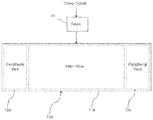
- an immersive display apparatus may include a display device 10 having a plurality of display parts 11 , 12 , 13 and a driver 14 for processing an input video signal through a predetermined procedure and supplying the processed signal to the display device 10 .
- the display device 10 may include a first display part 11 having a first display area and second display parts 12 , 13 having a second display area.
- a main-view video image may be displayed in the first display area of the first display part 11
- a peripheral view image may be displayed in the second display area of the second display parts 12 and 13 .
- the first display part 11 may be referred to as a main display part
- the second display parts 12 and 13 may be referred to as a peripheral display part.
- a video signal corresponding to the first display part 11 may be referred to as a main-view video signal, and a video signal corresponding to the second display part may be referred to as a peripheral view image signal.
- the first display part 11 and the second display parts 12 and 13 may be arranged to surround the user. In this case, the user may feel a stronger immersion feeling from the main-view video image displayed on the first display part 11 and the peripheral view image displayed on the second display parts 12 and 13 .
- a plurality of second display parts 12 , 13 may be arranged around the first display part 11 .
- the second-1 display part 12 is disposed at the right side of the first display part 11 and the second-2 display part 13 is disposed at the left side of the first display part 11 .
- FIG. 1 illustrates the case where two auxiliary display parts are arranged around the first display part 11
- the present disclosure may not be limited thereto.
- auxiliary display parts are arranged at top, bottom, left, and right sides of the first display part 11 , respectively.
- the driver 14 may process the input video signal to generate a peripheral view image to be displayed on the second display parts 12 and 13 .
- the driver 14 may include a pre-processing part 100 , a pre-warping part 110 , a sampling part 120 , a warping part 130 , a blending part 140 , and a controller 150 .
- the pre-processing part 100 may process the input video signal to obtain scene-space information.
- the video signal processed by the pre-processing part 100 may be a video signal corresponding to the first area of the display part 10 , namely the first display part 11 . If the driver 14 does not generate a peripheral view image, an image is displayed in the first display part 11 , but no image may be displayed in the second display parts 12 and 13 , corresponding to the input video signal.
- the scene-space information obtained by the pre-processing part 100 is information necessary for warping a video signal, and may include scene point information and camera parameter information.
- the scene point information may be 3D scene point information.
- the scene point information and the camera parameter information may be obtained through the structure-from-motion (SFM) technique.
- SFM structure-from-motion
- the scene point information may be information about a portion having predetermined image data on an image.
- the pre-warping part 110 may perform first warping to at least one neighborhood frame corresponding to a target frame included in the pro-processed video signal.
- performing the first warping to the neighborhood frame may be regarded as that the video signal corresponding to the neighborhood frame is primarily warped.
- Warping may mean that data about an image is transformed by means of shifting or the like based on information such as parallax of the image.
- the pre-warping part 110 may determine an outlier from the result of the first warping.
- the sampling part 120 may sample at least one neighborhood frame to be used for extrapolation from the result of the first warping by the pre-warping part 110 .
- the sampling part 120 may select at least one neighborhood frame suitable for generating a peripheral view image.
- the warping part 130 may perform second warping while excluding the outlier for the sampled frame by the sampling part 120 .
- performing the second warping to the sampled frame may be regarded as that a video signal corresponding to the neighborhood frame selected by the sampling part 120 is secondarily warped.
- the warping part 130 may generate a peripheral view image signal corresponding to a second area around the first area of the display part 10 , namely the second display parts 12 and 13 , from the result of the second warping.
- the warping part 130 may generate a peripheral view image by warping the sampled frame except for the outlier.
- the warping part 130 may obtain information about the outlier from the pre-warping part 110 to perform the second warping.
- the blending part 140 may blend the peripheral view image signal generated by the warping part 130 to the main-view video signal.
- the display part 10 may display an image corresponding to the video signal blended by the blending part 140 so that the image may be viewed.
- the controller 150 may perform overall control functions for image processing and image displaying.
- the controller 150 may be excluded.
- the pre-warping part 110 and the warping part 130 may be integrated into a single part in that they perform warping.
- the present disclosure may be not limited thereto.
- a display part 10 a may include a first area 11 a included in one screen and second areas 12 a and 13 a surrounding the first area 11 a.
- the main-view video image may be displayed in the first area 11 a of the display part 10 a and the peripheral view image may be displayed in the second areas 12 a , 13 a of the display part 10 a.
- An immersive display method according to the present disclosure may be applied to various types of display devices.
- FIGS. 4 to 18 are diagrams for illustrating an immersive display method for creation of a peripheral view image according to the present disclosure. In the following disclosure, any portion already explained above may not be described again.
- the input video signal may be pre-processed (S 200 ).
- scene-space information corresponding to the main-view video signal may be obtained.
- information about a scene point and information about a camera parameter for each frame included in the video signal may be obtained using the structure-from-motion (SFM) technique.
- SFM structure-from-motion
- the neighborhood frame NF corresponding to the target frame TF may be identified (S 210 ).
- the neighborhood frame NF corresponding to the target frame TF may be identified based on the scene-space information obtained in the pre-processing step (S 200 ).
- the neighborhood frame NF may be a frame adjacent to the target frame TF in time.
- neighborhood frame NF and the target frame TF may be included in the same shot (a single shot).
- a scene changes at a time t 1 between a first frame F 1 and a second frame F 2 , and then a scene changes again at a time t 2 between an n th frame Fn and an n+1 th frame Fn+1.
- the second frame F 2 to the n th frame Fn may be photographed corresponding to the same camera shot.
- the second frame F 2 to the n th frame Fn may be regarded as a frame group FG.
- a frame selected according to a predetermined criterion among the frames in the frame group FG other than the target frame TF is set as the neighborhood frame NF.
- the neighborhood frame NF corresponding to the target frame TF is set based on a screen change, it is possible to suppress an excessive increase in the amount of data to be processed.
- the neighborhood frame NF is set corresponding to target frame TF according to the above method, it is possible to sufficiently ensure similarity of image data between the target frame TF and the neighborhood frame NF. In this case, the visual and spatial coherence of the main-view video image and the peripheral view image may be improved.
- Each frame included in the frame group FG may be a target frame.
- the camera parameter corresponding to at least one neighborhood frame NF may be the same as the camera parameter corresponding to the target frame TF.
- the first warping may be performed to the video signal corresponding to the neighborhood frame.
- the first warping may be performed by transforming image data of the neighborhood frame NF to match the viewpoint of the neighborhood frame NF to the viewpoint of the target frame TF.
- the first warping will be described in more detail as follows with reference to FIG. 6 .
- the first warping may be performed to determine an outlier to be excluded in a following warping step (S 500 ) and to provide a criterion for frame sampling.
- the outlier may be generated by incompleteness of the structure-from-motion (SFM) technique.
- the first warping may be achieved by the content-preserving warping (CPW) Technique using a mesh optimization scheme.
- CPW content-preserving warping
- the first warping may be performed in such a way that the sum (Equation 3) of the energy calculated by Equation 1 and the energy calculated by Equation 2 is minimized.
- Equations 1, 2, and 3 are described in more detail below.
- Equation 1 may mean an energy function for displacement.
- R 90 may refer to a matrix corresponding to a 90 degree rotation.
- v1, v2, v3 denoted by an emphasis point may refer to a warped vertex with a triangle face f.
- Equation 3 may mean an energy function according to Equation 2.
- Equation 4 may mean the sum of the energy calculated by Equation 1 and the energy calculated by Equation 3.
- ⁇ may mean a spatial smoothness weight.
- Ptarget may refer to a projection point on the target frame TF.
- P k target may mean a k th projection point on the target frame TF.
- f(P k t) may be a set of indices for vertices including faces with (P k t).
- (W t j ) may be a barycentric weight of (P k t) with respect to the surrounding vertices.
- the projection point Pt may deviate from the field of view (FOV) of the t th frame.
- FOV field of view
- a triangulated grid mesh may be generated and applied to account for the projected point at a position beyond the input frame.
- Each frame has an initial grid mesh (V) consisting of ⁇ v j ⁇ .
- V initial grid mesh
- ⁇ v j ⁇ may mean a j th grid vertex.
- V denoted by an emphasis point may mean a warped mesh consisting of ⁇ v j ⁇ .
- Equation 1 the matching of P k target and (P k ) may be checked.
- R 90 may refer to a matrix corresponding to a 90 degree rotation.
- v t f1 ), (v t f2 ) and (v t f3 ) denoted by an emphasis point may refer to a vertex having a triangle face f.
- u and v which are coordinate information (local coordinate) may be calculated from the initial grid mesh (V).
- Equation 2 the maintenance of the initial shape of the initial grid mesh (V) may be checked.
- Equation 3 may refer to the sum of the energy calculated by Equation 1 and the energy calculated by Equation 2.
- Equation 3 As may mean a spatial smoothness weight.
- the first warping may be performed in such a way that the energy calculated by Equation 3 is minimized.
- the first warping may be performed iteratively for each target frame TF.
- the first warping may be performed to the input image (S 310 ), and the result of the first warping may be derived (S 320 ).
- a warping error may be determined using the result value for the first warping.
- a distance between Ptarget and Pt to which the emphasis point is given may be computed (S 340 ).
- the projection point may be determined as an outlier (S 350 ).
- the second scene point may be determined as an outlier if the distance between the first scene point and the second warping scene point is greater than the preset reference distance.
- the outlier determined in this way may be excluded from a following warping step. This will be described in more detail later.
- a sampling criterion required for frame sampling may be extracted using the result of the first warping.
- a portion (a peripheral view) newly added corresponding to the target frame TF may be determined using the result of the first warping (S 370 ).
- the sampling criterion may be extracted using information about the newly added portion (S 380 ).
- the neighborhood frame to be warped may be sampled according to the sampling criterion (S 400 ).
- the sampling criterion S 400
- at least one neighborhood frame to be used for extrapolation may be sampled from the result of the first warping.
- the selected neighborhood frame, or the sampled frame may mean a frame capable of providing effective data for generating a peripheral view image corresponding to the target frame TF.
- sampling criterion is described in more detail below.
- the sampled frame may contain a portion that does not overlap with the target frame.
- FIG. 8A may be referred to as an image corresponding to one frame group FG.
- the second, third and fourth frames F 2 , F 3 , F 4 may be neighborhood frames NF of the first frame F 1 , which is the target frame TF.
- the first frame F 1 which is the target frame, may correspond to a first portion IP 1 of the entire image A.
- the second frame F 2 corresponding to the first portion IP 1 of the entire image A, identical to the first frame F 1 may not be sampled.
- the second frame F 2 may not be sampled because the second frame F 2 does not contain any information which can be referred to when generating the peripheral view image corresponding to the first frame F 1 .
- the second frame F 2 equal to the first frame F 1 , which is the target frame TF, is set as the sampling frame in order to prevent errors in the following sampling process.
- the third frame F 3 may correspond to the second portion IP 2 of the entire image (A).
- the second portion IP 2 may be partially overlapped with the first portion IP 1 .
- the third frame F 3 may be set as a sampling frame for the first frame F 1 .
- the fourth frame F 4 may correspond to the third portion IP 3 of the entire image A.
- the third portion IP 3 may not overlap with the first portion IP 1 .
- the fourth frame F 4 may be set as a sampling frame for the first frame F 1 .
- the fourth frame F 4 should be sampled because the fourth frame F 4 may contain information that can be referred to in generating the peripheral view image corresponding to the first frame F 1 .
- At least one neighborhood frame is sampled considering the size of a peripheral view image to be added to the main-view video image.
- the image as in FIG. 9A is photographed with one shot, and the first frame F 1 is the target frame.
- the first frame F 1 which is the target frame TF, may correspond to the first area 11 a of the display part 10 , and the first frame F 1 may correspond to the first portion IP 1 a of the entire image A.
- the second frame F 2 may correspond to the second portion IP 2 a of the entire image A.
- the second portion IP 2 a may partially overlap with the first portion IP 1 a
- the second portion IP 2 a may partially overlap with the second areas 12 a , 13 a of the display part 10 .
- the second frame F 2 may be set as a sampling frame for the first frame F 1 .
- the third frame F 3 may correspond to the third portion IP 3 a of the entire image A.
- the third portion IP 3 a may not overlap with the first portion IP 1 a
- the third portion IP 3 a may not overlap with the second areas 12 a , 13 a of the display part 10 .
- the third frame F 3 may not be set as the sampling frame for the first frame F 1 .
- the third frame F 3 is not sampled because the third frame F 3 does not contain information about the image to be displayed in the second areas 12 a , 13 a of the display part 10 .
- At least one neighborhood frame is sampled based on information about the outlier included in the frame.
- information about the number of outliers per frame may be discriminated (S 381 ) from the result of the first warping in the sampling reference setting step S 380 .
- the frame may be set as an improper frame (S 383 ).
- the improper frame may mean a neighborhood frame that will not be sampled.
- the corresponding frame may be set as an appropriate frame suitable for sampling (S 384 ).
- the reason for the above sampling is that the number of outliers which is relatively small may mean that image distortion is not large.
- the method of sampling the neighborhood frame NF to be warped in the present disclosure may not be limited to the above description.
- a frame to be warped is randomly selected among a plurality of neighborhood frames NF.
- the frame to be sampled is set in the same way for each frame group FG.
- a first frame group FG 1 includes a first frame F 1 to an a th frame Fa and a second frame group FG 2 includes an a+1 th frames Fa+1 to an n th frame Fn.
- the first sampling frame group SFG 1 may be set corresponding to the first frame group FG 1 .
- all the neighborhood frames sampled corresponding to the respective target frames included in the first frame group FG 1 may be identically set as the first sampling frame group SFG 1 .
- the amount of data to be processed may be greatly reduced.
- second warping may be performed to the video signal corresponding to the sampled frame (S 500 ).
- the second warping will be described in more detail as follows with reference to FIG. 12 .
- the sampling frame may be warped except for the outliers determined in the first warping step (S 300 ).
- the second warping may be performed in such a way that the sum (Equation 7) of the energy calculated by Equation 4, the energy calculated by Equation 5 and the energy calculated by Equation 6 is minimized.
- Equations 4, 5, 6, and 7 will be described in more detail below. In the following description, the portions described in Equations 1, 2 and 3 may not be described in detail again.
- Equation 4 may mean an energy function for inter-frame coherency.
- Equation 4 it may be checked whether corresponding scene points are matched.
- Equation 5 may mean an energy function for preventing deformation of the original information (original content).
- Equation 6 may mean an energy function for temporal consistency.
- Equation 7 may mean the sum of the energy calculated by Equation 4, the energy calculated by Equation 5 and the energy calculated by Equation 6.
- Equation 7 ⁇ i may mean an inter-frame smoothness weight, ⁇ c may mean a temporal smoothness weight, and ⁇ tf may mean a target frame constraint weight.
- the second warping may be performed in such a way that the energy calculated by Equation 7 is minimized.
- the second warping may be iteratively performed for each target frame TF.
- a peripheral view image may be generated by means of the second warping.
- a peripheral view image signal corresponding to the second area around the first area may be generated by performing the second warping to the sampled frame, except for the outliers.
- inter-frame distortion may be caused in the peripheral view (PV) image around the main-view (MV) image.
- FIG. 14A shows outliers and inliers.
- the outliers are marked with red dots, and the inliers are marked with green dots.
- the outliers may correspond to a portion having a relatively high possibility of image distortion, and the inliers may correspond to a portion having a relatively low possibility of generating image distortion in comparison with the outliers.
- the peripheral view image is generated as a result of the second warping, as shown in the purple box of FIG. 14B , distortion may occur in the peripheral view image.
- FIG. 15A is compared with FIG. 14A , it may be found that the red dots are disappeared (controlled) on the screen.
- the peripheral view image generated by the second warping may be blended to the main-view video image (S 600 ).
- the peripheral view image signal may be blended to the main-view video signal.
- the peripheral view image signal may be blended to the main-view video signal in the order closer to the main-view video image corresponding to the target frame TF.
- a first peripheral view (PV 1 ) image closest to the main-view (MV) image is blended, then a second peripheral view (PV 2 ) image is blended to the first peripheral view (PV 1 ) image, and then a third peripheral view (PV 3 ) image is blended to the second peripheral view (PV 2 ) image.
- the peripheral view image is blended to the main-view video image in a plurality of directions.
- the peripheral view image is blended in a left direction of the target frame corresponding to the target frame and also the peripheral view image is blended in a right direction of the target frame.
- FIG. 18 shows an example in which a peripheral view image is generated according to the method of the present disclosure, and the generated peripheral view image is blended to the main view video image and displayed.
- FIG. 18A may be a main-view video image as a video corresponding to the video signal input to the driver 14 .
- FIG. 18B may be an image obtained by generating a peripheral view image (PVL, PVR) by the driver 14 according to the method of the present disclosure and then blending the image with the main-view video image.
- This image may be referred to as an immersive video.
- the resolution corresponding to the main-view video signal and the resolution corresponding to the peripheral view image signal may be the same.
- the quality of the immersive image may be improved.
Landscapes
- Engineering & Computer Science (AREA)
- Theoretical Computer Science (AREA)
- Physics & Mathematics (AREA)
- General Physics & Mathematics (AREA)
- Multimedia (AREA)
- Human Computer Interaction (AREA)
- General Engineering & Computer Science (AREA)
- Signal Processing (AREA)
- Closed-Circuit Television Systems (AREA)
- Controls And Circuits For Display Device (AREA)
Abstract
Description
Claims (20)
Applications Claiming Priority (2)
| Application Number | Priority Date | Filing Date | Title |
|---|---|---|---|
| KR1020170041918A KR101760639B1 (en) | 2017-03-31 | 2017-03-31 | Immersive Display Apparatus and Method for Creation of Peripheral View corresponding to Input Video |
| KR10-2017-0041918 | 2017-03-31 |
Publications (2)
| Publication Number | Publication Date |
|---|---|
| US20180286013A1 US20180286013A1 (en) | 2018-10-04 |
| US10586306B2 true US10586306B2 (en) | 2020-03-10 |
Family
ID=59428992
Family Applications (1)
| Application Number | Title | Priority Date | Filing Date |
|---|---|---|---|
| US15/648,030 Active US10586306B2 (en) | 2017-03-31 | 2017-07-12 | Immersive display apparatus and method for creation of peripheral view corresponding to input video |
Country Status (2)
| Country | Link |
|---|---|
| US (1) | US10586306B2 (en) |
| KR (1) | KR101760639B1 (en) |
Cited By (1)
| Publication number | Priority date | Publication date | Assignee | Title |
|---|---|---|---|---|
| US11153539B2 (en) * | 2019-06-20 | 2021-10-19 | Google Llc | Methods and systems to pre-warp and image |
Families Citing this family (3)
| Publication number | Priority date | Publication date | Assignee | Title |
|---|---|---|---|---|
| CN108492724A (en) * | 2018-02-05 | 2018-09-04 | 中国科学院长春光学精密机械与物理研究所 | A kind of immersion display device and VR equipment adapting to visual characteristic |
| BR112021020654A2 (en) | 2019-05-14 | 2022-01-25 | Intel Corp | Device, at least one machine-readable medium, system and method for encoding immersive video |
| US11432009B2 (en) * | 2019-07-02 | 2022-08-30 | Intel Corporation | Techniques for encoding and decoding immersive video |
Citations (10)
| Publication number | Priority date | Publication date | Assignee | Title |
|---|---|---|---|---|
| US6393162B1 (en) * | 1998-01-09 | 2002-05-21 | Olympus Optical Co., Ltd. | Image synthesizing apparatus |
| KR20110088515A (en) | 2008-10-27 | 2011-08-03 | 엘지전자 주식회사 | Virtual view image composition method and device |
| US20120223885A1 (en) * | 2011-03-02 | 2012-09-06 | Microsoft Corporation | Immersive display experience |
| US20130163896A1 (en) * | 2011-12-24 | 2013-06-27 | Ecole De Technologie Superieure | Image registration method and system robust to noise |
| US20130287304A1 (en) * | 2012-04-26 | 2013-10-31 | Sony Corporation | Image processing device, image processing method, and program |
| US20140118482A1 (en) * | 2012-10-26 | 2014-05-01 | Korea Advanced Institute Of Science And Technology | Method and apparatus for 2d to 3d conversion using panorama image |
| KR20150038954A (en) | 2013-10-01 | 2015-04-09 | 엘지디스플레이 주식회사 | Image processing device and method for autostereoscopic image display |
| KR20170027002A (en) | 2015-09-01 | 2017-03-09 | 삼성전자주식회사 | Method and apparatus for image processing |
| US20170202449A1 (en) * | 2014-09-05 | 2017-07-20 | Canon Kabushiki Kaisha | Image processing apparatus and control method of image processing apparatus |
| US20170244895A1 (en) * | 2016-02-24 | 2017-08-24 | Project Ray Ltd. | System and method for automatic remote assembly of partially overlapping images |
-
2017
- 2017-03-31 KR KR1020170041918A patent/KR101760639B1/en active Active
- 2017-07-12 US US15/648,030 patent/US10586306B2/en active Active
Patent Citations (13)
| Publication number | Priority date | Publication date | Assignee | Title |
|---|---|---|---|---|
| US6393162B1 (en) * | 1998-01-09 | 2002-05-21 | Olympus Optical Co., Ltd. | Image synthesizing apparatus |
| KR20110088515A (en) | 2008-10-27 | 2011-08-03 | 엘지전자 주식회사 | Virtual view image composition method and device |
| US20110255592A1 (en) * | 2008-10-27 | 2011-10-20 | Lg Electronics Inc. | Virtual view image synthesis method and apparatus |
| JP2014509759A (en) | 2011-03-02 | 2014-04-21 | マイクロソフト コーポレーション | Immersive display experience |
| US20120223885A1 (en) * | 2011-03-02 | 2012-09-06 | Microsoft Corporation | Immersive display experience |
| WO2012118769A2 (en) | 2011-03-02 | 2012-09-07 | Microsoft Corporation | Immersive display experience |
| US20130163896A1 (en) * | 2011-12-24 | 2013-06-27 | Ecole De Technologie Superieure | Image registration method and system robust to noise |
| US20130287304A1 (en) * | 2012-04-26 | 2013-10-31 | Sony Corporation | Image processing device, image processing method, and program |
| US20140118482A1 (en) * | 2012-10-26 | 2014-05-01 | Korea Advanced Institute Of Science And Technology | Method and apparatus for 2d to 3d conversion using panorama image |
| KR20150038954A (en) | 2013-10-01 | 2015-04-09 | 엘지디스플레이 주식회사 | Image processing device and method for autostereoscopic image display |
| US20170202449A1 (en) * | 2014-09-05 | 2017-07-20 | Canon Kabushiki Kaisha | Image processing apparatus and control method of image processing apparatus |
| KR20170027002A (en) | 2015-09-01 | 2017-03-09 | 삼성전자주식회사 | Method and apparatus for image processing |
| US20170244895A1 (en) * | 2016-02-24 | 2017-08-24 | Project Ray Ltd. | System and method for automatic remote assembly of partially overlapping images |
Non-Patent Citations (1)
| Title |
|---|
| Sang Youn Kim et al., "Immersive Multichannel Display for Virtual Reality", Digital Industrial Information, vol. 6, No. 3 (Sep. 2010) pp. 131-139. |
Cited By (3)
| Publication number | Priority date | Publication date | Assignee | Title |
|---|---|---|---|---|
| US11153539B2 (en) * | 2019-06-20 | 2021-10-19 | Google Llc | Methods and systems to pre-warp and image |
| US20220030203A1 (en) * | 2019-06-20 | 2022-01-27 | Google Llc | Methods and systems to pre-warp an image |
| US11647168B2 (en) * | 2019-06-20 | 2023-05-09 | Google Llc | Methods and systems to pre-warp an image |
Also Published As
| Publication number | Publication date |
|---|---|
| US20180286013A1 (en) | 2018-10-04 |
| KR101760639B1 (en) | 2017-07-24 |
Similar Documents
| Publication | Publication Date | Title |
|---|---|---|
| US11178428B2 (en) | Image splicing method and apparatus, and storage medium | |
| US10304161B2 (en) | Image processing apparatus, control method, and recording medium | |
| US9172947B2 (en) | Method and apparatus for processing multi-view image using hole rendering | |
| US9811946B1 (en) | High resolution (HR) panorama generation without ghosting artifacts using multiple HR images mapped to a low resolution 360-degree image | |
| JP5964741B2 (en) | Multi-viewpoint generation method and apparatus | |
| US10586306B2 (en) | Immersive display apparatus and method for creation of peripheral view corresponding to input video | |
| US20140118482A1 (en) | Method and apparatus for 2d to 3d conversion using panorama image | |
| US10999500B2 (en) | Imaging apparatus and imaging method, and image processing apparatus and image processing method | |
| US20060072852A1 (en) | Deghosting mosaics using multiperspective plane sweep | |
| CN104272377B (en) | Moving picture project management system | |
| US20220148129A1 (en) | Image fusion method and portable terminal | |
| US8009899B2 (en) | Image filling methods | |
| US20210350559A1 (en) | Image depth estimation method and apparatus, electronic device, and storage medium | |
| CN107451952B (en) | Splicing and fusing method, equipment and system for panoramic video | |
| US20200410638A1 (en) | Apparatus and method for synthesizing virtual viewpoint images | |
| JP5225313B2 (en) | Image generating apparatus, image generating method, and program | |
| US8942513B2 (en) | De-warping processing method for digital images | |
| US11416978B2 (en) | Image processing apparatus, control method and non-transitory computer-readable recording medium therefor | |
| JP3197801B2 (en) | 2D display image generation method | |
| JP6417204B2 (en) | Image processing apparatus and image processing method | |
| CN112565623A (en) | Dynamic image display system | |
| US11830177B2 (en) | Image processing apparatus, control method and non-transitory computer-readable recording medium therefor | |
| US10915603B2 (en) | Method for estimating suitability as multi-screen projecting type theatre system | |
| Xiong et al. | Fast and high-quality image blending on mobile phones | |
| JP6386670B2 (en) | Image processing device |
Legal Events
| Date | Code | Title | Description |
|---|---|---|---|
| AS | Assignment |
Owner name: KOREA ADVANCED INSTITUTE OF SCIENCE AND TECHNOLOGY, KOREA, REPUBLIC OF Free format text: ASSIGNMENT OF ASSIGNORS INTEREST;ASSIGNORS:NOH, JUNYONG;LEE, SANGWOO;LEE, JUNGJIN;AND OTHERS;REEL/FRAME:042989/0433 Effective date: 20170623 Owner name: KOREA ADVANCED INSTITUTE OF SCIENCE AND TECHNOLOGY Free format text: ASSIGNMENT OF ASSIGNORS INTEREST;ASSIGNORS:NOH, JUNYONG;LEE, SANGWOO;LEE, JUNGJIN;AND OTHERS;REEL/FRAME:042989/0433 Effective date: 20170623 |
|
| STPP | Information on status: patent application and granting procedure in general |
Free format text: FINAL REJECTION MAILED |
|
| STPP | Information on status: patent application and granting procedure in general |
Free format text: DOCKETED NEW CASE - READY FOR EXAMINATION |
|
| STPP | Information on status: patent application and granting procedure in general |
Free format text: NOTICE OF ALLOWANCE MAILED -- APPLICATION RECEIVED IN OFFICE OF PUBLICATIONS |
|
| STPP | Information on status: patent application and granting procedure in general |
Free format text: AWAITING TC RESP., ISSUE FEE NOT PAID |
|
| STPP | Information on status: patent application and granting procedure in general |
Free format text: PUBLICATIONS -- ISSUE FEE PAYMENT RECEIVED |
|
| STCF | Information on status: patent grant |
Free format text: PATENTED CASE |
|
| FEPP | Fee payment procedure |
Free format text: MAINTENANCE FEE REMINDER MAILED (ORIGINAL EVENT CODE: REM.); ENTITY STATUS OF PATENT OWNER: SMALL ENTITY |
|
| FEPP | Fee payment procedure |
Free format text: SURCHARGE FOR LATE PAYMENT, SMALL ENTITY (ORIGINAL EVENT CODE: M2554); ENTITY STATUS OF PATENT OWNER: SMALL ENTITY |
|
| MAFP | Maintenance fee payment |
Free format text: PAYMENT OF MAINTENANCE FEE, 4TH YR, SMALL ENTITY (ORIGINAL EVENT CODE: M2551); ENTITY STATUS OF PATENT OWNER: SMALL ENTITY Year of fee payment: 4 |