US10585463B1 - Luminous fan - Google Patents
Luminous fan Download PDFInfo
- Publication number
- US10585463B1 US10585463B1 US16/364,665 US201916364665A US10585463B1 US 10585463 B1 US10585463 B1 US 10585463B1 US 201916364665 A US201916364665 A US 201916364665A US 10585463 B1 US10585463 B1 US 10585463B1
- Authority
- US
- United States
- Prior art keywords
- light
- ring
- bracket
- luminous fan
- disposed
- Prior art date
- Legal status (The legal status is an assumption and is not a legal conclusion. Google has not performed a legal analysis and makes no representation as to the accuracy of the status listed.)
- Expired - Fee Related
Links
Images


Classifications
-
- F—MECHANICAL ENGINEERING; LIGHTING; HEATING; WEAPONS; BLASTING
- F04—POSITIVE - DISPLACEMENT MACHINES FOR LIQUIDS; PUMPS FOR LIQUIDS OR ELASTIC FLUIDS
- F04D—NON-POSITIVE-DISPLACEMENT PUMPS
- F04D25/00—Pumping installations or systems
- F04D25/02—Units comprising pumps and their driving means
- F04D25/06—Units comprising pumps and their driving means the pump being electrically driven
- F04D25/0606—Units comprising pumps and their driving means the pump being electrically driven the electric motor being specially adapted for integration in the pump
- F04D25/0613—Units comprising pumps and their driving means the pump being electrically driven the electric motor being specially adapted for integration in the pump the electric motor being of the inside-out type, i.e. the rotor is arranged radially outside a central stator
- F04D25/0646—Details of the stator
-
- F—MECHANICAL ENGINEERING; LIGHTING; HEATING; WEAPONS; BLASTING
- F04—POSITIVE - DISPLACEMENT MACHINES FOR LIQUIDS; PUMPS FOR LIQUIDS OR ELASTIC FLUIDS
- F04D—NON-POSITIVE-DISPLACEMENT PUMPS
- F04D25/00—Pumping installations or systems
- F04D25/02—Units comprising pumps and their driving means
- F04D25/06—Units comprising pumps and their driving means the pump being electrically driven
- F04D25/0606—Units comprising pumps and their driving means the pump being electrically driven the electric motor being specially adapted for integration in the pump
- F04D25/0613—Units comprising pumps and their driving means the pump being electrically driven the electric motor being specially adapted for integration in the pump the electric motor being of the inside-out type, i.e. the rotor is arranged radially outside a central stator
-
- F—MECHANICAL ENGINEERING; LIGHTING; HEATING; WEAPONS; BLASTING
- F04—POSITIVE - DISPLACEMENT MACHINES FOR LIQUIDS; PUMPS FOR LIQUIDS OR ELASTIC FLUIDS
- F04D—NON-POSITIVE-DISPLACEMENT PUMPS
- F04D29/00—Details, component parts, or accessories
- F04D29/005—Decorative aspects, i.e. features which have no effect on the functioning of the pump
-
- F—MECHANICAL ENGINEERING; LIGHTING; HEATING; WEAPONS; BLASTING
- F21—LIGHTING
- F21V—FUNCTIONAL FEATURES OR DETAILS OF LIGHTING DEVICES OR SYSTEMS THEREOF; STRUCTURAL COMBINATIONS OF LIGHTING DEVICES WITH OTHER ARTICLES, NOT OTHERWISE PROVIDED FOR
- F21V33/00—Structural combinations of lighting devices with other articles, not otherwise provided for
- F21V33/0088—Ventilating systems
- F21V33/0096—Fans, e.g. ceiling fans
-
- G—PHYSICS
- G02—OPTICS
- G02B—OPTICAL ELEMENTS, SYSTEMS OR APPARATUS
- G02B19/00—Condensers, e.g. light collectors or similar non-imaging optics
- G02B19/0004—Condensers, e.g. light collectors or similar non-imaging optics characterised by the optical means employed
- G02B19/0009—Condensers, e.g. light collectors or similar non-imaging optics characterised by the optical means employed having refractive surfaces only
- G02B19/0014—Condensers, e.g. light collectors or similar non-imaging optics characterised by the optical means employed having refractive surfaces only at least one surface having optical power
-
- G—PHYSICS
- G02—OPTICS
- G02B—OPTICAL ELEMENTS, SYSTEMS OR APPARATUS
- G02B19/00—Condensers, e.g. light collectors or similar non-imaging optics
- G02B19/0033—Condensers, e.g. light collectors or similar non-imaging optics characterised by the use
- G02B19/0047—Condensers, e.g. light collectors or similar non-imaging optics characterised by the use for use with a light source
- G02B19/0061—Condensers, e.g. light collectors or similar non-imaging optics characterised by the use for use with a light source the light source comprising a LED
-
- G—PHYSICS
- G02—OPTICS
- G02B—OPTICAL ELEMENTS, SYSTEMS OR APPARATUS
- G02B27/00—Optical systems or apparatus not provided for by any of the groups G02B1/00 - G02B26/00, G02B30/00
- G02B27/09—Beam shaping, e.g. changing the cross-sectional area, not otherwise provided for
- G02B27/0938—Using specific optical elements
- G02B27/095—Refractive optical elements
- G02B27/0955—Lenses
-
- G—PHYSICS
- G02—OPTICS
- G02B—OPTICAL ELEMENTS, SYSTEMS OR APPARATUS
- G02B3/00—Simple or compound lenses
- G02B3/02—Simple or compound lenses with non-spherical faces
- G02B3/06—Simple or compound lenses with non-spherical faces with cylindrical or toric faces
-
- G—PHYSICS
- G02—OPTICS
- G02B—OPTICAL ELEMENTS, SYSTEMS OR APPARATUS
- G02B6/00—Light guides; Structural details of arrangements comprising light guides and other optical elements, e.g. couplings
- G02B6/0001—Light guides; Structural details of arrangements comprising light guides and other optical elements, e.g. couplings specially adapted for lighting devices or systems
- G02B6/0003—Light guides; Structural details of arrangements comprising light guides and other optical elements, e.g. couplings specially adapted for lighting devices or systems the light guides being doped with fluorescent agents
-
- G—PHYSICS
- G02—OPTICS
- G02B—OPTICAL ELEMENTS, SYSTEMS OR APPARATUS
- G02B6/00—Light guides; Structural details of arrangements comprising light guides and other optical elements, e.g. couplings
- G02B6/0001—Light guides; Structural details of arrangements comprising light guides and other optical elements, e.g. couplings specially adapted for lighting devices or systems
- G02B6/0011—Light guides; Structural details of arrangements comprising light guides and other optical elements, e.g. couplings specially adapted for lighting devices or systems the light guides being planar or of plate-like form
- G02B6/0013—Means for improving the coupling-in of light from the light source into the light guide
- G02B6/0023—Means for improving the coupling-in of light from the light source into the light guide provided by one optical element, or plurality thereof, placed between the light guide and the light source, or around the light source
- G02B6/0028—Light guide, e.g. taper
-
- G—PHYSICS
- G02—OPTICS
- G02B—OPTICAL ELEMENTS, SYSTEMS OR APPARATUS
- G02B6/00—Light guides; Structural details of arrangements comprising light guides and other optical elements, e.g. couplings
- G02B6/0001—Light guides; Structural details of arrangements comprising light guides and other optical elements, e.g. couplings specially adapted for lighting devices or systems
- G02B6/0011—Light guides; Structural details of arrangements comprising light guides and other optical elements, e.g. couplings specially adapted for lighting devices or systems the light guides being planar or of plate-like form
- G02B6/0081—Mechanical or electrical aspects of the light guide and light source in the lighting device peculiar to the adaptation to planar light guides, e.g. concerning packaging
- G02B6/0095—Light guides as housings, housing portions, shelves, doors, tiles, windows, or the like
-
- G—PHYSICS
- G02—OPTICS
- G02B—OPTICAL ELEMENTS, SYSTEMS OR APPARATUS
- G02B7/00—Mountings, adjusting means, or light-tight connections, for optical elements
- G02B7/02—Mountings, adjusting means, or light-tight connections, for optical elements for lenses
- G02B7/021—Mountings, adjusting means, or light-tight connections, for optical elements for lenses for more than one lens
-
- G—PHYSICS
- G06—COMPUTING OR CALCULATING; COUNTING
- G06F—ELECTRIC DIGITAL DATA PROCESSING
- G06F1/00—Details not covered by groups G06F3/00 - G06F13/00 and G06F21/00
- G06F1/16—Constructional details or arrangements
- G06F1/20—Cooling means
-
- H—ELECTRICITY
- H05—ELECTRIC TECHNIQUES NOT OTHERWISE PROVIDED FOR
- H05K—PRINTED CIRCUITS; CASINGS OR CONSTRUCTIONAL DETAILS OF ELECTRIC APPARATUS; MANUFACTURE OF ASSEMBLAGES OF ELECTRICAL COMPONENTS
- H05K1/00—Printed circuits
- H05K1/02—Details
- H05K1/0201—Thermal arrangements, e.g. for cooling, heating or preventing overheating
- H05K1/0203—Cooling of mounted components
-
- H—ELECTRICITY
- H05—ELECTRIC TECHNIQUES NOT OTHERWISE PROVIDED FOR
- H05K—PRINTED CIRCUITS; CASINGS OR CONSTRUCTIONAL DETAILS OF ELECTRIC APPARATUS; MANUFACTURE OF ASSEMBLAGES OF ELECTRICAL COMPONENTS
- H05K1/00—Printed circuits
- H05K1/02—Details
- H05K1/14—Structural association of two or more printed circuits
- H05K1/147—Structural association of two or more printed circuits at least one of the printed circuits being bent or folded, e.g. by using a flexible printed circuit
-
- F—MECHANICAL ENGINEERING; LIGHTING; HEATING; WEAPONS; BLASTING
- F21—LIGHTING
- F21Y—INDEXING SCHEME ASSOCIATED WITH SUBCLASSES F21K, F21L, F21S and F21V, RELATING TO THE FORM OR THE KIND OF THE LIGHT SOURCES OR OF THE COLOUR OF THE LIGHT EMITTED
- F21Y2115/00—Light-generating elements of semiconductor light sources
- F21Y2115/10—Light-emitting diodes [LED]
-
- H—ELECTRICITY
- H05—ELECTRIC TECHNIQUES NOT OTHERWISE PROVIDED FOR
- H05K—PRINTED CIRCUITS; CASINGS OR CONSTRUCTIONAL DETAILS OF ELECTRIC APPARATUS; MANUFACTURE OF ASSEMBLAGES OF ELECTRICAL COMPONENTS
- H05K2201/00—Indexing scheme relating to printed circuits covered by H05K1/00
- H05K2201/05—Flexible printed circuits [FPCs]
- H05K2201/056—Folded around rigid support or component
-
- H—ELECTRICITY
- H05—ELECTRIC TECHNIQUES NOT OTHERWISE PROVIDED FOR
- H05K—PRINTED CIRCUITS; CASINGS OR CONSTRUCTIONAL DETAILS OF ELECTRIC APPARATUS; MANUFACTURE OF ASSEMBLAGES OF ELECTRICAL COMPONENTS
- H05K2201/00—Indexing scheme relating to printed circuits covered by H05K1/00
- H05K2201/09—Shape and layout
- H05K2201/09009—Substrate related
- H05K2201/09027—Non-rectangular flat PCB, e.g. circular
-
- H—ELECTRICITY
- H05—ELECTRIC TECHNIQUES NOT OTHERWISE PROVIDED FOR
- H05K—PRINTED CIRCUITS; CASINGS OR CONSTRUCTIONAL DETAILS OF ELECTRIC APPARATUS; MANUFACTURE OF ASSEMBLAGES OF ELECTRICAL COMPONENTS
- H05K2201/00—Indexing scheme relating to printed circuits covered by H05K1/00
- H05K2201/10—Details of components or other objects attached to or integrated in a printed circuit board
- H05K2201/10007—Types of components
- H05K2201/10106—Light emitting diode [LED]
-
- H—ELECTRICITY
- H05—ELECTRIC TECHNIQUES NOT OTHERWISE PROVIDED FOR
- H05K—PRINTED CIRCUITS; CASINGS OR CONSTRUCTIONAL DETAILS OF ELECTRIC APPARATUS; MANUFACTURE OF ASSEMBLAGES OF ELECTRICAL COMPONENTS
- H05K2201/00—Indexing scheme relating to printed circuits covered by H05K1/00
- H05K2201/20—Details of printed circuits not provided for in H05K2201/01 - H05K2201/10
- H05K2201/2027—Guiding means, e.g. for guiding flexible circuits
Definitions
- the present invention relates to a fan, and more particularly to a luminous fan.
- the host of the home computer is equipped with a cooling fan.
- the cooling fan is used for dissipating the heat from the casing of the host. Since the overheating problem is avoided, the processor, the motherboard or the hard drive in the host is not damaged.
- a computer host with a transparent casing has been introduced into the market.
- the inner structure or condition within the computer host can be directly observed through the transparent casing.
- the computer host may be further equipped with a luminous fan.
- the luminous fan emits a light beam and the luminous fan is operated to remove heat. Consequently, the computer host is operated stably and the appearance of the computer host becomes more modern.
- the solid state light sources e.g., light emitting diode
- the illumination modules of various luminous fans have been widely used.
- the use of the solid state light source still has some drawbacks. For example, since the light beam from the solid state light source travels along a linear trajectory, the diffraction angle is small. As the volume of the luminous fan is reduced, the propagation path of the light beam is shortened and the projection area of the light beam is centralized. Consequently, the overall luminous intensity of the luminous fan is reduced. Since the light beam is centralized, the brightness of the projected location of the light beam is not uniform, and hot spots are generated at the projected location. Due to the generation of the hot spots, the luminous fan cannot provide the uniform luminous efficacy.
- the present invention provides a luminous fan for increasing the light utilization efficiency, enhancing the overall luminous intensity and avoiding the generation of the hot spots.
- the present invention provides a luminous fan for increasing the light utilization efficiency, enhancing the overall luminous intensity and avoiding the generation of the hot spots. Consequently, the luminous fan can provide the uniform luminous efficacy.
- a luminous fan in accordance with an aspect of the present invention, includes a supporting mechanism, a main circuit board, a light-guiding impeller and an illumination module.
- the supporting mechanism includes a bracket.
- the main circuit board is disposed on the bracket.
- the light-guiding impeller is pivotally coupled to the bracket, and rotatable relative to the bracket.
- the light-guiding impeller includes a hub and plural blades. The plural blades are circumferentially disposed on a lateral part of the hub.
- the illumination module is disposed within the hub, and includes a lens assembly and a light source.
- the lens assembly includes at least one secondary lens.
- the light source includes at least one light-emitting element. After a light beam from the at least one light-emitting element is emitted to the lens assembly, the light beam is refracted by the at least one secondary lens and transmitted to the light-guiding impeller, so that the light-guiding impeller is illuminated.
- a ring-shaped inner wall structure is disposed within the hub, and the ring-shaped inner wall structure is circumferentially installed on a top part of the hub.
- An inner space of the hub is divided into a first accommodation space and a second accommodation space by the ring-shaped inner wall structure.
- the illumination module is disposed within the second accommodation space.
- the luminous fan further includes a rotator assembly and a stator assembly.
- the rotator assembly and the stator assembly are disposed within the first accommodation space.
- stator assembly is disposed on the bracket, and the rotator assembly is fixed on a surface of the ring-shaped inner wall structure.
- the lens assembly further includes a light guide part and a support part.
- the support part is connected with the light guide part.
- the light guide part includes an outer surface and an inner surface, which are opposed to each other.
- the at least one secondary lens is disposed on the outer surface of the light guide part.
- a position-limiting protrusion structure is protruded from a side of the inner surface of the support part, and a ring-shaped accommodation space is formed between the inner surface of the support part and the position-limiting protrusion structure.
- the light source includes a ring-shaped circuit board and at least one light-emitting element.
- the at least one light-emitting element is installed on a surface of the ring-shaped circuit board.
- the ring-shaped circuit board is fixed in the ring-shaped accommodation space, and the at least one light-emitting element faces the inner surface of the support part.
- a fixing groove is formed in a periphery region of the bracket.
- the support part is accommodated within the fixing groove.
- the position-limiting protrusion structure is in contact with the bracket and an edge of the main circuit board.
- a shaft coupling structure is protruded from the bracket, and the shaft coupling structure is pivotally coupled to the light-guiding impeller.
- the lens assembly has a ring-shaped lens structure.
- FIG. 1A is a schematic perspective view illustrating a luminous fan according to an embodiment of the present invention
- FIG. 1B is a schematic exploded view illustrating the luminous fan according to the embodiment of the present invention.
- FIG. 1C is a schematic cutaway and exploded view illustrating the illumination module of the luminous fan according to the embodiment of the present invention
- FIG. 2 is schematic perspective view illustrating the luminous fan according to the embodiment of the present invention and taken along a topside viewpoint;
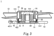
- FIG. 3 is a schematic cross-sectional view illustrating the luminous fan according to the embodiment of the present invention.
- FIG. 4 is a schematic enlarged view of the region A as shown in FIG. 3 .
- FIG. 1A is a schematic perspective view illustrating a luminous fan according to an embodiment of the present invention.
- FIG. 1B is a schematic exploded view illustrating the luminous fan according to the embodiment of the present invention.
- the luminous fan 1 comprises a light-guiding impeller 10 , a rotator assembly 20 , a stator assembly 30 , an illumination module 40 , a supporting mechanism 50 and a main circuit board 60 .
- the light-guiding impeller 10 comprises a hub 11 and plural blades 12 .
- the blades 12 are circumferentially disposed on a lateral part of the hub 11 .
- a ring-shaped inner wall structure 111 is circumferentially installed on a top part of the hub 11 .
- the inner space of the hub 11 is divided into a first accommodation space 51 and a second accommodation space S 2 .
- the second accommodation space S 2 is arranged around the first accommodation space 51 .
- a rotation shaft (not shown) is disposed within the first accommodation space S 1 and connected with the top part of the hub 11 .
- the light-guiding impeller 10 is made of light-transmissible/light-guiding material such as polycarbonate (PC) or acrylic resin.
- diffusion powder or phosphor powder is added to and mixed with the light-transmissible/light-guiding material during the process of fabricating the light-guiding impeller 10 . Consequently, the overall light-guiding efficacy or illuminating efficacy of the light-guiding impeller 10 is increased.
- the illumination module 40 comprises a light source 41 and a lens assembly 42 .
- the lens assembly 42 has a ring-shaped lens structure.
- the supporting mechanism 50 comprises a bracket 51 and plural ribs 52 .
- the first ends of the ribs 52 are connected with the bracket 51 .
- the second ends of the ribs 52 are connected with a fan frame (not shown).
- the main circuit board 60 is disposed on the bracket 51 .
- the rotator assembly 20 and the stator assembly 30 are accommodated within the first accommodation space S 1 .
- the stator assembly 30 is disposed on the bracket 51 and located over the main circuit board 60 .
- the rotator assembly 20 is fixed on a surface of the ring-shaped inner wall structure 111 and aligned with the stator assembly 30 .
- a fixing groove 512 is formed in a periphery region of the bracket 51 .
- the illumination module 40 is accommodated and fixed in the fixing groove 512 .
- a shaft coupling structure 511 is protruded from a middle region of the bracket 51 .
- the shaft coupling structure 511 is pivotally coupled to a rotation shaft (not shown), which is installed on a top part of the hub 11 . Consequently, the light-guiding impeller 10 is rotatable relative to the bracket 51 .
- the main circuit board 60 is used for controlling and powering the illumination module 40 and the stator assembly 30 .
- the main circuit board 60 controls the illumination module 40 to emit the light beam to the hub 11 or the blades 12 .
- the main circuit board 60 further controls the power level of the stator assembly 30 in order to adjust the rotating speed of the light-guiding impeller 10 .
- FIG. 1C is a schematic cutaway and exploded view illustrating the illumination module of the luminous fan according to the embodiment of the present invention.
- the light source 41 comprises a ring-shaped circuit board 412 and a light-emitting element 413 .
- the light-emitting element 413 is installed on a surface of the ring-shaped circuit board 412 .
- the lens assembly 42 comprises a light guide part 421 and a support part 422 .
- the support part 422 is connected with the light guide part 421 .
- the light guide part 421 comprises an outer surface 4211 and an inner surface 4212 , which are opposed to each other.
- One or plural secondary lenses 42111 are formed on the outer surface 4211 .
- a position-limiting protrusion structure 4221 is protruded from a side of the inner surface 4212 of the support part 422 . Moreover, a ring-shaped accommodation space S 3 is formed between the inner surface 4212 and the position-limiting protrusion structure 4221 .
- the ring-shaped circuit board 412 is fixed in the ring-shaped accommodation space S 3 through an attaching means or a locking means.
- the light-emitting element 413 faces the inner surface 4212 .
- An example of the light-emitting element 413 includes but is not limited to a light emitting diode (LED), an organic light emitting diode (OLED), a quantum dots light emitting diode (QLED) or an electroluminescence (EL) unit.
- FIG. 2 is schematic perspective view illustrating the luminous fan according to the embodiment of the present invention and taken along a topside viewpoint.
- FIG. 3 is a schematic cross-sectional view illustrating the luminous fan according to the embodiment of the present invention.
- the rotator assembly 20 and the stator assembly 30 are disposed within the first accommodation space S 1 .
- the shaft coupling structure 511 is disposed within the first accommodation space S 1 .
- the shaft coupling structure 511 and the hub 11 of the light-guiding impeller 10 are pivotally coupled to each other.
- the illumination module 40 is disposed within the second accommodation space S 2 .
- the illumination module 40 is located over the fixing groove 512 , which is formed in the periphery region of the bracket 51 .
- FIG. 4 is a schematic enlarged view of the region A as shown in FIG. 3 .
- the fixing groove 512 is formed in the periphery region of the bracket 51 , and the support part 422 of the lens assembly 42 is accommodated within the fixing groove 512 .
- the protrusion structure 4221 is protruded from the support part 422 and contacted with the bracket 51 and an edge of the main circuit board 60 . Consequently, the lens assembly 42 is fixed.
- the light-emitting element 413 emits a light beam L toward the inner surface 4212 of the light guide part 421 . Then, the light beam L is transmitted to the secondary lens 42111 through the inner surface 4212 of the light guide part 421 .
- the light beam L After the light beam L is refracted by the secondary lens 42111 , the light beam L is projected to the hub 11 or the blades 12 . Since the light beam L collected along the vertical axis is refracted by the secondary lens 42111 , the luminous intensity of the light-emitting element 413 is enhanced. Moreover, since the refracted light beam L is diffused along the horizontal axis, the possibility of generating the hot spots is effectively reduced and the overall brightness of the light-guiding impeller is more uniform.
- the illumination module 40 is fixed on the bracket 51 . It is noted that the illumination module 40 may be located at any position of the second accommodation space S 2 .
- the lens assembly 42 is disposed on a surface of the inner wall structure 111 and located at the same level with the installation position of the blade 12 .
- the secondary lens 42111 is aligned with the blades 12 . Consequently, the entire of the light beam L from the illumination module 40 can be received by the blades 12 . Under this circumstance, the light loss caused by refraction or reflection will be reduced.
- the present invention provides the luminous fan.
- the linear light beam from the light-emitting element is refracted by the secondary lens of the lens assembly. Consequently, the luminous intensity is enhanced.
- the linear light beam from the light-emitting element can be uniformly diffused through the secondary lens of the lens assembly. Consequently, the overall size and volume of the luminous fan are reduced, the possibility of generating the hot spots is effectively reduced, and the brightness of the luminous fan is more uniform. In other words, the luminous fan of the present invention is industrially valuable.
Landscapes
- Physics & Mathematics (AREA)
- Engineering & Computer Science (AREA)
- General Physics & Mathematics (AREA)
- Optics & Photonics (AREA)
- General Engineering & Computer Science (AREA)
- Theoretical Computer Science (AREA)
- Mechanical Engineering (AREA)
- Microelectronics & Electronic Packaging (AREA)
- Human Computer Interaction (AREA)
- Structures Of Non-Positive Displacement Pumps (AREA)
- Led Device Packages (AREA)
Abstract
Description
Claims (10)
Applications Claiming Priority (2)
| Application Number | Priority Date | Filing Date | Title |
|---|---|---|---|
| TW108105167A TWI687599B (en) | 2019-02-15 | 2019-02-15 | Fan with light |
| TW108105167A | 2019-02-15 |
Publications (1)
| Publication Number | Publication Date |
|---|---|
| US10585463B1 true US10585463B1 (en) | 2020-03-10 |
Family
ID=69723388
Family Applications (1)
| Application Number | Title | Priority Date | Filing Date |
|---|---|---|---|
| US16/364,665 Expired - Fee Related US10585463B1 (en) | 2019-02-15 | 2019-03-26 | Luminous fan |
Country Status (2)
| Country | Link |
|---|---|
| US (1) | US10585463B1 (en) |
| TW (1) | TWI687599B (en) |
Cited By (6)
| Publication number | Priority date | Publication date | Assignee | Title |
|---|---|---|---|---|
| US10900493B2 (en) * | 2019-01-29 | 2021-01-26 | Primax Electronics Ltd. | Luminous fan |
| US11086069B2 (en) * | 2018-09-10 | 2021-08-10 | Apple Inc. | Electronic device with illumination |
| CN114635864A (en) * | 2020-12-16 | 2022-06-17 | 技嘉科技股份有限公司 | Fan assembly |
| US12054283B1 (en) * | 2023-07-25 | 2024-08-06 | Honeywell International Inc. | Lighting system for preventing bird strikes and aircraft incorporating the same |
| US12092316B1 (en) * | 2023-03-15 | 2024-09-17 | Gd Midea Environment Appliances Mfg Co., Ltd. | Head assembly and fan apparatus |
| US12123425B1 (en) * | 2023-03-28 | 2024-10-22 | Sea Sonic Electronics Co., Ltd. | Partially luminous fan blade and fan containing same |
Citations (7)
| Publication number | Priority date | Publication date | Assignee | Title |
|---|---|---|---|---|
| US6790003B1 (en) * | 2003-06-09 | 2004-09-14 | Act-Rx Technology Corporation | Cooling fan with flashing light effect |
| US7563070B2 (en) * | 2005-10-27 | 2009-07-21 | Hong Fu Jin Precision Industry (Shen Zhen) Co., Ltd. | Cooling fan |
| US20160369809A1 (en) * | 2015-06-22 | 2016-12-22 | Paul Daniel Richter | Cooling Fan Illuminated With Addressable LEDs |
| US10082286B1 (en) * | 2018-01-24 | 2018-09-25 | Dynaeon Industrial Co., Ltd. | Cooling fan with light-emitting effect |
| US20190032912A1 (en) * | 2017-07-28 | 2019-01-31 | Dongguan City Hanshuo Plastic Co.,Ltd. | Heat dissipation fan structure capable of showing pattern of light |
| US20190154250A1 (en) * | 2017-11-22 | 2019-05-23 | Asia Vita Components Co., Ltd. | Fan structure |
| US20190249862A1 (en) * | 2018-02-14 | 2019-08-15 | Cooler Master Technology Inc. | Luminous fan and light guide member |
Family Cites Families (5)
| Publication number | Priority date | Publication date | Assignee | Title |
|---|---|---|---|---|
| TWI472686B (en) * | 2011-12-05 | 2015-02-11 | Giga Byte Tech Co Ltd | Fan module |
| CN206625993U (en) * | 2017-01-21 | 2017-11-10 | 东莞市擎宇电子科技有限公司 | Improved luminous fan |
| CN207297418U (en) * | 2017-09-01 | 2018-05-01 | 东莞动利电子有限公司 | Luminous impeller and cooling fan with luminous impeller |
| CN208073868U (en) * | 2018-01-09 | 2018-11-09 | 东莞动利电子有限公司 | A kind of luminous flabellum and its fan structure |
| TWM568907U (en) * | 2018-06-01 | 2018-10-21 | 中國商佛山市建準電子有限公司 | fan |
-
2019
- 2019-02-15 TW TW108105167A patent/TWI687599B/en not_active IP Right Cessation
- 2019-03-26 US US16/364,665 patent/US10585463B1/en not_active Expired - Fee Related
Patent Citations (7)
| Publication number | Priority date | Publication date | Assignee | Title |
|---|---|---|---|---|
| US6790003B1 (en) * | 2003-06-09 | 2004-09-14 | Act-Rx Technology Corporation | Cooling fan with flashing light effect |
| US7563070B2 (en) * | 2005-10-27 | 2009-07-21 | Hong Fu Jin Precision Industry (Shen Zhen) Co., Ltd. | Cooling fan |
| US20160369809A1 (en) * | 2015-06-22 | 2016-12-22 | Paul Daniel Richter | Cooling Fan Illuminated With Addressable LEDs |
| US20190032912A1 (en) * | 2017-07-28 | 2019-01-31 | Dongguan City Hanshuo Plastic Co.,Ltd. | Heat dissipation fan structure capable of showing pattern of light |
| US20190154250A1 (en) * | 2017-11-22 | 2019-05-23 | Asia Vita Components Co., Ltd. | Fan structure |
| US10082286B1 (en) * | 2018-01-24 | 2018-09-25 | Dynaeon Industrial Co., Ltd. | Cooling fan with light-emitting effect |
| US20190249862A1 (en) * | 2018-02-14 | 2019-08-15 | Cooler Master Technology Inc. | Luminous fan and light guide member |
Cited By (9)
| Publication number | Priority date | Publication date | Assignee | Title |
|---|---|---|---|---|
| US11086069B2 (en) * | 2018-09-10 | 2021-08-10 | Apple Inc. | Electronic device with illumination |
| US10900493B2 (en) * | 2019-01-29 | 2021-01-26 | Primax Electronics Ltd. | Luminous fan |
| CN114635864A (en) * | 2020-12-16 | 2022-06-17 | 技嘉科技股份有限公司 | Fan assembly |
| CN114635864B (en) * | 2020-12-16 | 2024-03-08 | 技嘉科技股份有限公司 | Fan assembly |
| US12092316B1 (en) * | 2023-03-15 | 2024-09-17 | Gd Midea Environment Appliances Mfg Co., Ltd. | Head assembly and fan apparatus |
| US20240310033A1 (en) * | 2023-03-15 | 2024-09-19 | Gd Midea Environment Appliances Mfg Co., Ltd. | Head assembly and fan apparatus |
| US12123425B1 (en) * | 2023-03-28 | 2024-10-22 | Sea Sonic Electronics Co., Ltd. | Partially luminous fan blade and fan containing same |
| US12497973B2 (en) | 2023-03-28 | 2025-12-16 | Sea Sonic Electronics Co., Ltd. | Partially luminous fan blade and fan containing same |
| US12054283B1 (en) * | 2023-07-25 | 2024-08-06 | Honeywell International Inc. | Lighting system for preventing bird strikes and aircraft incorporating the same |
Also Published As
| Publication number | Publication date |
|---|---|
| TW202032017A (en) | 2020-09-01 |
| TWI687599B (en) | 2020-03-11 |
Similar Documents
| Publication | Publication Date | Title |
|---|---|---|
| US10585463B1 (en) | Luminous fan | |
| US10900493B2 (en) | Luminous fan | |
| US6790003B1 (en) | Cooling fan with flashing light effect | |
| US7789546B2 (en) | Light-emitting device and electronic device using the same | |
| US20200072231A1 (en) | Luminous fan | |
| JP4989170B2 (en) | Compact LED lamp | |
| US10082286B1 (en) | Cooling fan with light-emitting effect | |
| TWI406058B (en) | Backlight module | |
| US8696163B2 (en) | Lamp with wide-angle light emission and bulb thereof | |
| US20120127741A1 (en) | Lamp unit and lighting fixture | |
| US20120127739A1 (en) | Lamp unit and lighting fixture | |
| JP2017022032A (en) | Vehicle lighting | |
| CN117345665A (en) | Luminous fan | |
| US20200116348A1 (en) | Cooling fan | |
| CN106062465A (en) | Light source apparatus and lighting apparatus | |
| US10429059B1 (en) | Cooling fan | |
| JP2012243713A (en) | Lighting device | |
| US10982815B2 (en) | Lighting device and LED circuit board with a center opening with a protrusion | |
| CN103968283B (en) | Bulb type lighting device | |
| CN111577623B (en) | Luminous fan | |
| JP2013026087A (en) | Lighting system | |
| US7654675B2 (en) | Light assembly for an image projector | |
| TWM531987U (en) | Centrifugal fan module | |
| US20130016519A1 (en) | Light source module | |
| TWM640354U (en) | light fan |
Legal Events
| Date | Code | Title | Description |
|---|---|---|---|
| FEPP | Fee payment procedure |
Free format text: ENTITY STATUS SET TO UNDISCOUNTED (ORIGINAL EVENT CODE: BIG.); ENTITY STATUS OF PATENT OWNER: LARGE ENTITY |
|
| STCF | Information on status: patent grant |
Free format text: PATENTED CASE |
|
| FEPP | Fee payment procedure |
Free format text: MAINTENANCE FEE REMINDER MAILED (ORIGINAL EVENT CODE: REM.); ENTITY STATUS OF PATENT OWNER: LARGE ENTITY |
|
| LAPS | Lapse for failure to pay maintenance fees |
Free format text: PATENT EXPIRED FOR FAILURE TO PAY MAINTENANCE FEES (ORIGINAL EVENT CODE: EXP.); ENTITY STATUS OF PATENT OWNER: LARGE ENTITY |
|
| STCH | Information on status: patent discontinuation |
Free format text: PATENT EXPIRED DUE TO NONPAYMENT OF MAINTENANCE FEES UNDER 37 CFR 1.362 |
|
| FP | Lapsed due to failure to pay maintenance fee |
Effective date: 20240310 |