TECHNICAL FIELD
The present invention relates to a method for manufacturing a ring-shaped member such as a bearing ring for a radial rolling bearing, and to a manufacturing apparatus for a ring-shaped member that can be directly used when performing this manufacturing method.
BACKGROUND ART
Radial ball bearings 1 such as illustrated in FIG. 21 are assembled in rotary member support sections of various kinds of rotating equipment. As a radial ball bearing 1, a single-row deep-groove radial ball bearing is used in which a plurality of balls 4 are rotatably provided between an outer ring 2 and an inner ring 3 that are concentric with each other. A deep-groove outer-ring raceway 5 is formed around the entire circumference of a middle portion in the axial direction of the inner-circumferential surface of the outer ring 2, and a deep-groove inner-ring raceway 6 is formed around the entire circumference of a middle portion in the axial direction of the outer-circumferential surface of the inner ring 3. With the plurality of balls 4 that are held by a cage 7 rotatably provided between the outer-ring raceway 5 and the inner-ring raceway 6, the outer ring 2 and inner ring 3 freely rotate relative to each other.
A low cost method for manufacturing bearing rings such as the outer ring 2 and the inner ring 3 of a radial ball bearing 1 such as described above is disclosed in JP2009-279611 (A). In this method, first, in a state in which the outer diameter of a bottom-end section of a circular column-shaped billet 8 illustrated in FIG. 22A is restrained, by crushing the billet 8 in the axial direction by performing an upsetting process on the billet 8, a first intermediate blank 11 having small-diameter section 9 and large-diameter section 10 such as illustrated in FIG. 22B is formed. Next, by processing the small-diameter section 9 into a small-diameter second cylindrical section 12 by performing a forward extrusion process on the small-diameter section 9, a second intermediate blank 13 as illustrated in FIG. 22C is obtained. Then, by further processing the large-diameter section 10 into a large-diameter first cylindrical section 14 by performing a rear extrusion process on the large-diameter section 10, a third intermediate blank 15 as illustrated in FIG. 22D is obtained. After that, by punching out a bottom-plate section 16 of the third intermediate blank 15 by performing a punching process on the third intermediate blank 15, a fourth intermediate blank 17 as illustrated in FIG. 22E is obtained. Then, as illustrated in FIG. 22F, a small-diameter cylindrical member 18 is obtained by punching out a portion that corresponds to the second cylindrical section 12 from the fourth intermediate blank 17 by performing a punching process on the fourth intermediate blank 17. Finally, as illustrated in FIG. 22G, a large-diameter cylindrical member 20 is obtained by punching out an inward-facing flange section 19 from a portion that corresponds to the first cylindrical section 14. Both the small-diameter cylindrical member 18 and large-diameter cylindrical member 20 that are obtained in this way are annular shaped metal members.
The small-diameter cylindrical member 18 is the blank for the inner ring 3, however, an inner-ring raceway 6 is not formed around the outer-circumferential surface of the small-diameter cylindrical member 18, and the outer diameter dimension, the axial-direction dimension, and the shape of the inner-circumferential surface and the outer-circumferential surface are not the dimensions and shape of the inner ring 3. Moreover, the large-diameter cylindrical member 20 is the blank for the outer ring 2, however, an outer-ring raceway 5 is not formed around the inner-circumferential surface of the large-diameter cylindrical member 20, and the inner-diameter dimension, the outer-diameter dimension, the axial-direction dimension, and the shape of the inner-circumferential surface and the outer-circumferential surface are not the dimensions and shape of the outer ring 2. Performing work to process the small-diameter cylindrical member 18 into the shape of the inner ring 3, and to process the large-diameter cylindrical member 20 into the shape of the outer ring 2 by a rolling process is disclosed in JP2009279611 (A) and JPS59212142 (A).
FIG. 23 and FIG. 24 illustrate a manufacturing apparatus 21 for a ring-shaped member as disclosed in JPS59212142. The manufacturing apparatus 21 is an apparatus for processing annular shaped metal blank 26 such as the small-diameter cylindrical member 18 into a ring-shaped member 22 such as the inner ring 3 by performing a rolling process, and includes a mandrel 23, a forming roll 24, and a support roll 25.
The mandrel 23 has a first rolling surface 27 for performing a rolling process on the inner-circumferential surface of the metal blank 26, and a pair of cylindrical surface shaped mandrel-side regulating surfaces 28 that are provided on both sides in the axial direction of the first rolling surface 27. The first rolling surface 27 is such that the middle portion in the axial direction has a cylindrical surface shape (cross-sectional linear shape) of which the outer diameter does not change with respect to the axial direction, and the portions near both ends in the axial direction have cross-sectional arc shapes of which the outer diameter becomes larger going toward both ends in the axial direction. The mandrel 23 is supported by a cradle 29 so that displacement in the axial direction (up-down direction in FIG. 23 and FIG. 24), and rotation around the center axis of the mandrel 23 are possible.
The forming roll 24 has: a second rolling surface 30 that has a cylindrical shape and is formed around the middle section in the axial direction of the outer-circumferential surface, and is for performing a rolling process on the outer-circumferential surface of the metal blank 26; and a pair of cylindrical surface shaped forming-roll-side regulating surfaces 31 that are formed on both side in the axial direction of the second rolling surface 30. The second rolling surface 30 is such that the portions near both ends in the axial direction have a cylindrical surface shape (cross-sectional linear shape) of which the outer diameter does not change in the axial direction, and the portion near the center in the axial direction has a cross-sectional arc shape of which the outer diameter becomes larger going toward the center in the axial direction. The forming roll 24, is such that in a state in which the center axis of the forming roll 24 is parallel with the center axis of the mandrel 23, the second rolling surface 30 is made to face the first rolling surface 27 of the mandrel 23. The forming roll 24 is able to displace (move toward or away from the mandrel 23) in the horizontal direction (left-right direction in FIG. 23 and FIG. 24) while rotating.
The support roll 25 includes a pair of rollers 32 that arranged with a specified space in the axial direction provided in between. The support roll 25 is provided on the opposite side of the forming roll 24 with respect to the center axis of the mandrel 23 so that the center axis of the support roll 25 is parallel with the center axis of the mandrel 23, and part of the outer-circumferential surface of the roller 32 is made to face the mandrel-side regulating surface 28. The rotating shaft of the forming roll 24 and the rotating shaft of the support roll 25 are coupled together by a synchronizing mechanism 33, and the forming roll 24 and support roll 25 are able to rotate in synchronization, being rotated and driven by an electric motor 34.
Next, the procedure for manufacturing the ring-shaped member 22 by performing a rolling process on the metal blank 26 using the manufacturing apparatus 21 for a ring-shaped member will be explained with reference to FIG. 24. First, as illustrating in FIG. 24A, in a state in which the mandrel 23 is inserted into the space in the radial direction of the metal blank 26, part in the circumferential direction of the metal blank 26 is arranged between the first rolling surface 27 of the mandrel 23 and the second rolling surface 30 of the forming roll 24. Part in the circumferential direction of the outer-circumferential surface of the pair of rollers 32 of the support roll 25 are made to closely face the pair of mandrel-side regulating surfaces 28 of the mandrel 23.
Next, in a state in which the forming roll 24 and the support roll 25 are rotated and driven by rotating and driving the electric motor 34, the forming roll 24 is made to displace in a direction toward the mandrel 23 (toward the left side in FIG. 23 and FIG. 24). As a result, the outer-circumferential surface of the forming roll 24 comes in contact with the outer-circumferential surface of the metal blank 26, which causes the metal blank 26 to rotate. As the forming roll 24 is made to displace further toward that mandrel 23 from the state of contact between the outer-circumferential surface of the forming roll 24 and outer-circumferential surface of the metal blank 26, the mandrel 23 is pressed by way of the metal blank 26, and the outer-circumferential surface of the mandrel 23 comes in contact with the outer-circumferential surfaces of the pair of rollers 32 of the support roll 25. In a state in which the outer-circumferential surface of the mandrel 23 is in contact with the outer-circumferential surface of the rollers 32, the mandrel 23 is made to rotate due to the rotation of the rollers 32. In this state in which the outer-circumferential surface of the mandrel 23 is in contact with the outer-circumferential surface of the rollers 32, the support roll 25 supports the mandrel 23 so that the mandrel 23 does not displace toward the left side in FIG. 23 and FIG. 24.
As the forming roll 24 is made to further displace in a direction toward the mandrel 23 from a state in which the outer-circumferential surface of the mandrel 23 is in contact with the outer-circumferential surface of the rollers 32, part in the circumferential direction of the metal blank 26 is pressed in between the forming roll 24 and the mandrel 23 that is supported by the support roll 25, and at the same time that the first rolling surface 27 of the mandrel 23 is rolled over the inner-circumferential surface of the metal blank 26, the second rolling surface 30 of the forming roll 24 is rolled over the outer-circumferential surface of the metal blank 26. As this kind of rolling process is performed, the outer-diameter dimension and the axial-direction dimension of the metal blank 26 increase. When the forming-roll-side regulating surface 31 of the forming roll 24 comes in contact with the mandrel-side regulating surface 28 of the mandrel 23, displacement of the forming roll 24 in the direction toward the mandrel 23 is stopped, and the rolling process ends. The inner ring 3 is obtained by performing a cutting process, a grinding process and a finishing process on the ring-shaped member 22 that was obtained by this kind of rolling process.
With this kind of manufacturing method for a ring-shaped member, it is possible to make the processing apparatus more compact than in the case of manufacturing a ring-shaped member 22 by performing a forging process on the metal blank 26, and it is possible to make the machining allowance small when performing a cutting process and a turning process, so it is possible to reduce the equipment cost and material cost. However, in this kind of manufacturing method, means for regulating the outer-diameter dimension of the ring-shaped member are not provided, so there is a possibility that variation in the shape (outer-diameter dimension and axial-direction dimension) of the ring-shaped member 22 will occur due to variation in the outer-dimensional shape of the metal blank 26 or due to variation in the assembled state of the metal blank 26 in a processing apparatus. When variation in the shape of the ring-shaped member 22 occurs, there is a possibility that the finishing process (cutting process and grinding process) will become troublesome, and that manufacturing costs will increase.
In JPH07275990 (A), technology is disclosed in which variation in the shape of a ring-shaped member is prevented by using a metal die that is capable of regulating the outer-diameter dimension and axial-direction of a ring-shaped member after a rolling process. However, in this technology, when the volume of the metal blank being used is larger than a specified value, the molding space of the metal die will become filled by the metal blank in a step before pressure by the forming roll is finished, and there is a possibility that the internal stress on this metal blank will become to high, and that it will become easy for damage to the mandrel to occur. Even when the mandrel is not damaged, the metal blank which had no place to go in the molding space of the metal die is distorted and thus there is a possibility that the roundness of the ring-shaped member becomes bad. When there is damage to the mandrel or when the roundness of the ring-shaped member becomes bad, there is a possibility that a change in volume of the metal blank will occur due to a temperature change in the metal die.
RELATED LITERATURE
Patent Literature
[Patent Literature 1] JP2009279611 (A)
[Patent Literature 2] JPS59212142 (A)
[Patent Literature 3] JPH07275990 (A)
SUMMARY OF INVENTION
Problem to be Solved by Invention
Taking into consideration the problems described above, the object of the present invention is to proved a manufacturing method and a manufacturing apparatus for a ring-shaped member that are capable of preventing the occurrence of damage to a mandrel, and capable of improving the precision of the shape of a ring-shaped member after processing regardless of variation in the volume of a metal blank.
Means for Solving Problems
The manufacturing apparatus for a ring-shaped member of the present invention is an apparatus for forming a ring-shaped member by performing a rolling process on the inner-circumferential surface and outer-circumferential surface of an annular-shaped metal blank, and includes a mandrel, an outer-diameter constraining die, and an excess material release means.
The mandrel is rotatably supported around the center axis of the mandrel, and has a pair of support shaft sections and a rolling shaft section, in which the pair of support shaft sections have a larger diameter than the rolling shaft section, and are provided so as to be separated in the axial direction from each other and concentric with each other, and the rolling shaft section is provided between the pair of support shaft sections so as to be concentric with the pair of support shaft sections, and has a first rolling surface for performing a rolling process on the inner-circumferential surface of the metal blank being formed around the outer circumferential surface thereof.
The outer-diameter constraining die has an annular shape, is supported in a state in which the center axis of the outer-diameter constraining die is parallel with the center axis of the mandrel and is able to rotate around the center axis of the outer-diameter constraining die, has a second rolling surface for performing a rolling process on the outer-circumferential surface of the metal blank being formed around the inner-circumferential surface thereof, and is arranged so that the rolling shaft section is inserted into the inner-diameter side thereof and the second rolling surface faces the first rolling surface.
The excess material release means is such that by displacing in the axial direction and/or radial direction when a pressing force having a specified size or greater is received from the metal blank in the axial direction and/or radial direction during processing of the metal blank, a molding space that is defined by the first rolling surface of the mandrel, the second rolling surface of the outer-diameter constraining die, and the end surfaces on the rolling shaft section side of the pair of support shaft sections expands, allowing the excess material of the metal blank to be released.
The manufacturing apparatus for a ring-shaped member of the present invention forms the ring-shaped member, in a state in which part in the circumferential direction of the metal blank is arranged in the molding space, by performing a rolling process on the inner-circumferential surface and outer-circumferential surface of the metal blank by rotating the mandrel around the center axis of the mandrel together with rotating the outer-diameter constraining die around the center axis of the outer-diameter constraining die, and pressing the metal blank between the first rolling surface and the second rolling surface.
A first aspect of a manufacturing apparatus for a ring-shaped member of the present invention is such that the excess material release means is at least one support shaft section of the pair of support shaft sections, the at least one support shaft section formed separately from the rolling shaft section, and during processing of the metal blank, when the at least one support shaft section receives a pressing force in the axial direction from the metal blank that is a specified size or greater, the at least one support shaft section is able to displace in the axial direction in a direction going away from the rolling shaft section.
In this first aspect of a manufacturing apparatus for a ring-shaped member, preferably the manufacturing apparatus for a ring-shaped member further comprises an energizing means that elastically presses the at least one support shaft section in the axial direction in a direction toward the rolling shaft section.
In this first aspect of a manufacturing apparatus for a ring-shaped member, the outer-diameter constraining die has a plurality of outer-diameter constraining die elements that have an annular shape and are arranged side-by-side in the axial direction, and the second rolling surface is constructed by the inner-circumferential surfaces of the plurality of outer-diameter constraining die elements and is for performing a rolling process on the outer-circumferential surface of the metal blank in order to form chamfer sections in the corner sections that are connecting sections between the outer-circumferential surface and both end surfaces in the axial direction of metal blank, and the plurality of outer-diameter constraining die elements are able to displace in a direction going away from each other when, during processing of the metal blank, pressing forces in the axial direction having a specified size or greater are received from the metal blank.
In this case, preferably the outer-diameter constraining die further comprise an annular-shaped outer-circumference holding member, and the outer-diameter constraining die is formed by fitting the outer-circumference holding member around the outer-circumferential surfaces of the plurality of outer-diameter constraining die elements in a state that allows the plurality of outer-diameter constraining die elements to displace in the axial direction.
A second aspect of a manufacturing apparatus for a ring-shaped member of the present invention is such that the excess material release means is a movable annular-shaped member that is provided in a portion that faces the inner-circumferential surface of the metal blank when using the manufacturing apparatus for a ring-shaped member, a portion of the rolling shaft section that is separated in the axial direction from the portion where the first rolling surface is formed is inserted into the inner side in the radial direction of the movable annular-shaped member, and that movable annular-shaped member is able to displace in the radial direction when, during processing of the metal blank, a pressing force in the radial direction having a specified size or greater is received from the metal blank.
A manufacturing method for a ring-shaped member of the present invention uses the manufacturing apparatus for a ring-shaped member of the invention such as described above and forms a ring-shaped member by performing a rolling process on the inner-circumferential surface and outer-circumferential surface of an annular-shaped metal blank. In the case of the manufacturing method for a ring-shaped member of the present invention, the excess material release means expands the molding space and allows excess material of the metal blank to be released by displacing in the axial direction and/or radial direction when, during processing of the metal blank, a pressing force in the axial direction and/or radial direction having a specified size or greater is received from the metal blank.
Effect of Invention
With the present invention, it is possible to prevent the occurrence of damage to the mandrel and improve the precision of the shape of a ring-shaped member after processing regardless of variation in the volume of a metal blank. In other words, in the present invention, construction is such that an excess material release means is able to displace in the axial direction and/or radial direction when, during processing of a metal blank, a pressing force having a specified size or greater is received in the axial direction and/or radial direction from the blank material. Therefore, even when the internal stress inside the metal blank inside the molding space increases during processing of the metal blank, the excess material release means displaces in the axial direction and/or radial direction, making it possible for the molding space to expand and for excess material of the metal blank to be released to the expanded portion. As a result, the internal stress inside the metal blank inside the molding space decreases, and thus it is possible to reduce the stress applied to the mandrel. Moreover, the internal stress inside the metal blank can be reduced during processing, so it is possible to prevent the metal blank from being distorted inside the molding space. Consequently, it is possible to prevent the roundness of the ring-shaped member from becoming worse during processing.
Even in the case where the volume of a metal blank is greater than a specified size (target volume of the ring-shaped member) due to variation in the volume of the metal blank, there is a possibility that the internal stress inside the metal blank inside the molding space will increase. Even in a case such as this, with the present invention, displacement of the excess material release means makes it possible to reduce the internal stress inside the metal blank and thus reduce the stress applied to the mandrel, and it is possible to prevent the metal blank from being distorted inside the molding space.
BRIEF DESCRIPTION OF DRAWINGS
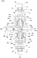
FIG. 1 is a cross-sectional view illustrating a manufacturing apparatus for a ring-shaped member of a first example of an embodiment of the present invention;
FIG. 2 is an enlarged cross-sectional view that corresponds to A in FIG. 1;
FIG. 3 is a cross-sectional view of part of a mandrel of a second example of an embodiment of the present invention;
FIG. 4 is a cross-sectional view similar to FIG. 1, and illustrates a third example of an embodiment of the present invention;
FIG. 5 is a cross-sectional view similar to FIG. 1, and illustrates a fourth example of an embodiment of the present invention;
FIG. 6 is a cross-sectional view similar to FIG. 1, and illustrates a fifth example of an embodiment of the present invention;
FIG. 7 is a cross-sectional view similar to FIG. 1, and illustrates a sixth example of an embodiment of the present invention;
FIG. 8 is an enlarged cross-sectional view that corresponds to B in FIG. 7;
FIG. 9 is an enlarged cross-sectional view that corresponds to C in FIG. 8;
FIG. 10A is a cross-sectional view illustrating an outer-diameter constraining die of a seventh example of an embodiment of the present invention, and FIG. 10B is a side view as seen from below in FIG. 10A of this outer-diameter constraining die;
FIG. 11 is a cross-sectional view similar to FIG. 1, and illustrates an eighth example of an embodiment of the present invention;
FIG. 12 is a cross-sectional view similar to FIG. 1, and illustrates a ninth example of an embodiment of the present invention;
FIG. 13 is a cross-sectional view similar to FIG. 1, and illustrates a tenth example of an embodiment of the present invention;
FIG. 14A illustrates the state before beginning processing of a portion that corresponds to D in FIG. 8 of the manufacturing apparatus for a ring-shaped member of the tenth example of an embodiment of the present invention, and FIG. 14B illustrates the state after processing of this portion;
FIG. 15 is a cross-sectional view similar to FIG. 1, and illustrates an eleventh example of an embodiment of the present invention;
FIG. 16 is an enlarged cross-sectional view that corresponds to E in FIG. 15;
FIG. 17A illustrates the state before beginning processing of a portion that corresponds to F in FIG. 15, and FIG. 17B illustrates the state after processing is ended;
FIG. 18 is a cross-sectional view similar to FIG. 1, and illustrates a twelfth example of an embodiment of the present invention;
FIG. 19 illustrates a portion corresponding to cross-section G-G in FIG. 18, which part of the members omitted;
FIG. 20 is similar to FIG. 16, and illustrates a thirteenth example of an embodiment of the present invention;
FIG. 21 is a partial perspective view that illustrates an example of a rolling bearing in which an outer ring and an inner ring that are objects of the manufacturing method of the present invention are assembled;
FIG. 22A to FIG. 22G are cross-sectional views that illustrate an example of a known process for forming an annular shaped metal blank;
FIG. 23 illustrates a rolling apparatus that was conventionally used; and
FIG. 24A and FIG. 24B are for explaining a procedure for processing a metal blank into a ring-shaped member by using a conventional rolling apparatus.
DETAILED DESCRIPTION OF THE INVENTION
First Example
FIG. 1 and FIG. 23 illustrate a first example of an embodiment of the present invention. Features of the manufacturing method and manufacturing apparatus for a ring-shaped member of this example are construction for regulating the outer-diameter dimension of a ring-shaped member 35 after processing, and a means for removing excess material in order to allow excess material of a metal blank 26 to be released in the axial direction during processing of the metal blank 26. The construction and functions of the other parts are the same as those of the conventional manufacturing method and manufacturing apparatus illustrated in FIG. 23 and FIGS. 24A and 24B. This example illustrates a manufacturing method and manufacturing apparatus for making a ring-shaped member for an outer ring by performing a rolling process on a metal blank 26. However, the manufacturing method and manufacturing apparatus for a ring-shaped member of the present invention can also be applied to a ring-shaped member for an inner ring as in the case of the conventional manufacturing method and manufacturing apparatus illustrated in FIG. 23 and FIGS. 24A and 24B.
The manufacturing apparatus 21 a for a ring-shaped member of this example includes a mandrel 23 a, an outer-diameter constraining die 36, a forming roll 24 a and a support roll 25 a. The mandrel 23 a has a pair of support shaft sections 37 a, 37 b that are each made of a metal such as die steel, high-speed steel, cemented carbide and the like, and that are provided so as to be concentric with each other and separated from each other in the axial direction, and a rolling shaft section 38 that is concentrically provided in the axial direction between the pair of support shaft sections 37 a, 37 b.
Of the pair of support shaft sections 37 a, 37 b, one (top one in FIG. 1) of the support shaft sections 37 a is a hollow shaft that has a center hole 39 a through the center that is open on both ends in the axial direction. Of this center hole 39 a, a threaded hole 40 a is formed in a portion near one end in the axial direction (top end in FIG. 1), and of this center hole 39 a, a fitting hole 41 a having a larger diameter than the middle section in the axial direction is formed in a portion near the other end in the axial direction (bottom end in FIG. 1). A small-diameter cylindrical section 42 a is formed on half of one side in the axial direction of the outer-circumferential surface of the one support shaft section 37 a, and the diameter thereof is smaller than the half on the other side in the axial direction and does not change in the axial direction. The half on the other side of the outer-circumferential surface of the one support shaft section 37 a functions as a mandrel-side regulating surface 43 a. The center hole 39 a may also be used for inserting a rod-shaped knock-out jig through when removing a rolling shaft section 38 from the one support shaft section 37 a.
Of the pair of support shaft sections 37 a, 37 b, the other (bottom one in FIG. 1) support shaft section 37 b has a shape that is symmetrical with the one support-shaft section 37 a in the up-down direction of FIG. 1. In other words, the other support shaft section 37 b is a hollow shaft having a center hole 39 b in the center that is open on both ends in the axial direction. Of this center hole 39 b, a fitting hole 41 b having a diameter that is larger than the middle section in the axial direction is formed in the portion near one end in the axial direction (top end in FIG. 1), and of this center hole 39 b, a threaded hole 40 b is formed in the portion near the other end in the axial direction (bottom end in FIG. 1). A small-diameter cylindrical section 42 b is formed on half of the other side in the axial direction of the outer-circumferential surface of the other support shaft section 37 b, and the diameter thereof is smaller than the half on the one side in the axial direction and does not change in the axial direction. The half on the one side of the outer-circumferential surface of the other support shaft section 37 b functions as a mandrel-side regulating surface 43 b. The pair of support shaft sections 37 a, 37 b are preferably made of a metal such as cemented carbide that has high rigidity. Moreover, the outer-diameter dimension of the pair of support shaft sections 37 a, 37 b can be appropriately set, and when the outer-diameter dimension of the support shaft sections 37 a, 37 b is small, preferably the pair of support shaft sections 37 a, 37 b are made of steel such as die steel, high-speed steel, or the like that does not crack easily.
The rolling shaft 38 is a solid rod-shaped member having an axial-direction dimension that is smaller than the pair of support shaft sections 37 a, 37 b, and includes a pair of fitting sections 44 a, 44 b that are provided on portions near both ends in the axial direction, and a rolling surface section 45 that is provided in the axial direction between the pair of fitting sections 44 a, 44 b. The pair of fitting sections 44 a, 44 b have a circular column shape, the outer diameter of which does not change in the axial direction. The outer-diameter dimension of one fitting section 44 a of the pair of fitting sections 44 a, 44 b is a little larger than the inner-diameter dimension of the fitting hole 41 a of the one support shaft section 37 a, and the outer-diameter dimension of the other fitting section 44 b of the pair of fitting sections 44 a, 44 b is a little smaller than the inner-diameter dimension of the fitting hole 41 b of the other support shaft section 37 b.
The rolling surface section 45 is such that a first rolling surface 46 for performing a rolling process on the inner-circumferential surface of the metal blank 26 is formed around the outer-circumferential surface thereof. The first rolling surface 46 has a shape that corresponds to the shape of the inner-circumferential surface of the ring-shaped member 35 that will be obtained by performing a rolling process on the metal blank 26, and includes a raceway forming section 47 that is formed around the middle section in the axial direction, a pair of cylindrical surface sections 48 that are formed around both sides in the axial direction of the raceway forming section 47, and groove forming sections 49 that are formed around portions near both ends in the axial direction. The raceway forming section 47 is for forming by rolling an outer-ring raceway around the inner-circumferential surface of the metal blank 26, and the cross-sectional shape (shape of the generating line) on an imaginary plane that passes through the center axis of the mandrel 23 a is a semicircular arc shape, the outer diameter of which becomes larger going toward the center in the axial direction. The pair of groove forming sections 49 are for forming by rolling locking grooves for locking the outer-circumferential edge of seal rings to portions near both ends in the axial direction of the inner-circumferential surface of the metal blank 26, and the cross-sectional shape (shape of the generating line) of the respective groove forming sections 49 on an imaginary plane that passes through the center axis of the mandrel 23 a is an S shape that smoothly connects a convex section that is formed on the side of the raceway forming section 47, and a concave section that is formed on both sides in the axial direction of the rolling surface section 45.
The rolling shaft section 38 is supported and fastened by one fitting section 44 a fitting inside the fitting hole 41 a of the one support shaft section 37 a with an interference fit, with displacement in the axial direction and inclination with respect to the one support shaft section 37 a being regulated. The rolling shaft section 38 can displace in the axial direction with respect to the other support shaft section 37 b by the other fitting section 44 b fitting inside the fitting hole 41 b of the other support shaft section 37 b with a loose fit. The outer-diameter dimension of the other fitting section 44 b and the inner-diameter dimension of the fitting hole 41 b of the other support shaft section 37 b are regulated within a range such that displacement in the axial direction of the rolling shaft section 38 with respect to the other support shaft section 37 b is possible, and so that looseness in the radial direction of the rolling shaft section 38 and the size of inclination with respect to the other support shaft section 37 b are a minimum.
The one support shaft section 37 a of the mandrel 23 a is supported by a fixed support section 51 a, which is fastened to and supported by a fixed portion of the housing or the like that does not displace during processing of the metal blank 26, by way of a double-row radial tapered roller bearing 50 a that is rotatably fitted around the outside of the small-diameter cylindrical section 42 a. The fixed support section 51 a, except during processing of the metal blank 26, can be moved out of the way in the axial direction for example, in order that the metal blank 26 can be mounted or removed. The surface on the other end in the axial direction of the inner ring of the radial tapered roller bearing 50 a comes in contact with a stepped section 53 a that connects the other end section in the axial direction of the small-diameter cylindrical section 42 a and the one end section in the axial direction of the mandrel-side regulating surface 43 a. The surface of the one end in the axial direction of radial tapered roller bearing 50 a comes in contact with the surface on the other end in the axial direction of a constraining member 54 a that is attached to the one end in the axial direction of the one support shaft section 37 a. With this kind of construction, it is possible to position the radial tapered roller bearing 50 a in the axial direction. The constraining member 54 a has a circular ring plate shape, and by passing a bolt 56 a through a through hole 55 a that is formed in the center section, and screwing that bolt 56 a into the threaded hole 40 a of the one support shaft section 37 a, the constraining member 54 a is attached to the one end section in the axial direction of this one support shaft section 37 a. The one support shaft section 37 a is supported by the fixed support section 51 a by way of the radial tapered roller bearing 50 a, so it is possible to reduce vibration of the other end section of the one support shaft section 37 a (end section on the side of the rolling shaft section 38).
The other support shaft section 37 b of the mandrel 23 a is supported by a displaceable support section 52 a by way of a double-row radial tapered roller bearing 50 b that is rotatably fitted around the outside of the small-diameter cylindrical section 42 b. The displaceable support 52 a is supported so as to be able to displace in the axial direction with respect to a fixed portion 57 such as a cradle that does not displace during processing of the metal blank 26, and other than during processing of the metal blank 26, can be moved out of the way in the axial direction, for example, in order mount or remove the metal blank 26.
The surface of the one end in the axial direction of the inner ring of the radial tapered roller bearing 50 b comes in contact with a stepped section 53 b that connects the one end section in the axial direction of the small-diameter cylindrical section 42 b and the other end section in the axial direction of the mandrel-side regulating surface 43 b. The surface of the other end in the axial direction of the inner ring of the radial tapered roller bearing 50 b comes in contact with the surface of the one end in the axial direction of a constraining member 54 b that is attached to the other end section in the axial direction of the other support shaft section 37 b. With this kind of construction, it is possible to position the radial tapered roller bearing 50 b in the axial direction. The constraining member 54 b has a circular column shape, and by passing a bolt 56 b through a stepped through hole 55 b that is formed in the center section, and screwing that bolt 56 b into the threaded hole 40 b of the other support shaft section 37 b, the constraining member 54 b is attached to the other end section in the axial direction of this other support shaft section 37 b.
Moreover, a mechanical type (spring or the like), hydraulic type, gas pressure type, or pneumatic type elastic member 58 is provided between the displaceable support section 52 a and the fixed portion 57, and the elastic member 58 elastically presses the other support shaft section 37 b toward the rolling shaft section 38 (upward in FIG. 1). In other words, in this example, the elastic member 58 corresponds to an energizing means. The other support shaft section 37 b and the displaceable support section 52 a can displace in the axial direction with respect to the one support shaft section 37 a and the rolling shaft section 38. The elastic force of the elastic member 58 (force pressing the other support shaft section 37 b) is appropriately set, however, the elastic force is set so as to be smaller than the pressing force by which metal blank 26 presses the other support shaft section 37 b in the axial direction when processing the metal blank 26 and in the state that the molding space that is formed between the first rolling surface 46 of the mandrel 23 a, the second rolling surface 59 of the outer-diameter constraining die 36, and the end surfaces on the rolling shaft section 38 side of the pair of support shaft sections 37 a, 37 b, is filled with the metal blank 26. From the aspect of synchronizing the movement in the horizontal direction (left-right direction in FIG. 1) of the one support shaft section 37 a and the other support shaft section 37 b, preferably the fixed support section 51 a and the displaceable support section 52 a are supported in common by the fixed portion 57.
The outer-diameter constraining die 36 is an annular shaped member that is made of a metal such as die steel, high-speed steel, cemented carbide or the like, and the outer circumferential surface is a cylindrical surface, the outer diameter of which does not change in the axial direction. A second rolling surface 59 for performing a rolling process on the outer-circumferential surface of the metal blank 26 is formed around the inner-circumferential surface of the outer-diameter constraining die 36. The second rolling surface 59 is a cylindrical surface, the inner diameter of which does not change in the axial direction. The outer-diameter constraining die 36 causes the second rolling surface 59 to face the first rolling surface 46 when the rolling shaft section 38 of the mandrel 23 is inserted inside in the radial direction. In this state, the center axis of the outer-diameter constraining die 36 is parallel with the center axis of the mandrel 23 a.
The forming roll 24 a has one metal roller 60 and a rotating shaft 61 that is inserted through the center hole in this roller 60, and is arranged on the outer-diameter side of the outer-diameter constraining die 36 with this rotating shaft 61 (center axis of the roller 60) being parallel to the center axes of the mandrel 23 a and the outer-diameter constraining die 36. The forming roll 24, as in the conventional construction described above and illustrated in FIG. 23 and FIGS. 24A and 24B, can be moved toward or away from the outer-diameter constraining die 36 (can displace in the horizontal direction or in the left-right direction in FIG. 1) by an actuator such as a hydraulic cylinder (not illustrated in the figures), while being rotated and driven by the rotation of the electric motor 34 (see FIG. 23).
The support roll 25 a includes a pair of metal rollers 62 a, 62 b, and a rotating shaft 63 that is inserted through this pair of rollers 62 a, 62 b. The support roll 25 a is arranged on the opposite side of the center axis of the mandrel 23 from the forming roll 24 a, with the rotating shaft 63 (center axis of rollers 62 a and 62 b) parallel to the center axes of the mandrel 23 a, outer-diameter constraining die 36 and forming roll 24 a. The support roll 25 a is rotated and driven in synchronization with the forming roll 24 a by rotating and driving the electric motor 34. The support roll 25 a is for regulating displacement of the mandrel 23 a toward the support roll 25 a side during processing by causing part of the outer-circumferential surfaces of the pair of rollers 62 a, 62 b to come in contact with the mandrel-side regulating surfaces 43 a, 43 b of the mandrel 23. In this example, the support roll 25 a is regulated during processing of the metal blank 26 so as not to displace in the horizontal direction, and the support roll 25 a does not press the mandrel 23 a toward the forming roll 24 a side. However, it is also possible to configure the support roll 25 a so that during processing of the metal blank 26 the support roll 25 a displaces toward the forming roll 24 a side and presses the mandrel 23 a toward the forming roll 24 a side. In this case, the forming roll 24 a can be configured so as to displace in the horizontal direction, or can be configured so as not to displace in the horizontal direction.
The procedure for manufacturing a ring-shaped member 35 by using a manufacturing apparatus 21 a for a ring-shaped member to perform a rolling process on a metal blank 26 will be explained. First, with the mandrel 23 a inserted through the inside in the radial direction of the metal blank 26, part in the circumferential direction of the metal blank 26 is placed inside a molding space that is formed between the first rolling surface 46 of the mandrel 23 a, the second rolling surface 59 of the outer-diameter constraining die 59, and the end surfaces on the rolling shaft section 38 side of the pair of support shaft sections 37 a, 37 b. Moreover, parts of the outer-circumferential surfaces of the pair of rollers 62 a, 62 b of the support roller 25 a are made to closely face the mandrel-side regulating surfaces 43 a, 43 b of the mandrel 23 a.
Next, when the forming roll 24 a and support roll 25 a are rotated and driven by rotating and driving the electric motor 34, the forming roll 24 a is displaced in the horizontal direction so as to move close to the outer-diameter constraining die 36, and the outer-circumferential surface of the roller 60 of the forming roll 24 a is made to come in contact with the outer-circumferential surface of the outer-diameter constraining die 36. The outer-diameter constraining die 36 is made to rotate due to the rotation of the forming roll 24 a.
When the forming roll 24 a is made to further displace (is pressed) toward the outer-diameter constraining die 36 from the state of the outer-circumferential surface of the roller 60 coming in contact with the outer-circumferential surface of the outer-diameter constraining die 36, the mandrel 23 a is pressed toward the left side in FIG. 1 by the roller 60 by way of the outer-diameter constraining die 36 and metal blank 26, and the outer-circumferential surfaces of the rollers 62 a, 62 b of the support roll 25 a strongly come into contact with (are pressed against) the mandrel-side regulating surfaces 43 a, 43 b of the mandrel 23. In this state, the mandrel 23 a is made to rotate due to the rotation of the rollers 62 a, 62 b of the support roll 25 a. Moreover, in this state, the outer-diameter constraining die 36 and mandrel 23 a rotate in synchronization, and the metal blank 26 rotates due to the rotation of the outer-diameter constraining die 36 and mandrel 23 a.
When displacing (pressing) the forming roll 24 a further toward the outer-diameter constraining die 36 from this state, first, both ends in the axial direction of the metal blank 26 are plastically deformed so that the axial-direction dimension of the metal blank 26 becomes larger until coming in contact with the end surfaces on the rolling shaft section 38 side of the pair of support shaft sections 37 a, 37 b. When both ends in the axial direction of the metal blank 26 come in contact with the end surfaces on the rolling shaft section 38 side of the pair of support shaft sections 37 a, 37 b, the outer-circumferential surface of the metal blank 26 is plastically deformed so that the outer diameter becomes larger until coming in contact with the inner-circumferential surface of the outer-diameter constraining die 36 around the entire circumference. Then the molding space that is formed between the first rolling surface 46 of the mandrel 23 a, the second rolling surface 59 of the outer-diameter constraining die 36, and the end surfaces on the rolling shaft section 38 side of the pair of support shaft sections 37 a, 37 b is filled with the metal blank 26. As a result, at the same time that the first rolling surface 46 of the mandrel 23 a is rolled by the inner-circumferential surface of the metal blank 26, the second rolling surface 59 of the outer-diameter constraining die 36 is rolled by the outer-circumferential surface of the metal blank 26. Of both end surfaces in the axial direction of the metal blank 26, the end surface on the other support shaft section 37 b side is in a state of contact with the other support shaft section 37 b, and in this state, a pressing force in the axial direction is applied to the other support shaft section 37 b from the metal blank 26. In this example, the elastic force of the elastic member 58 (force by which the elastic member 58 presses the other support shaft section 37 b) is set to be larger than the pressing force that is applied to the other support shaft section 37 b in the state before the molding space becomes filled with the metal blank 26. Therefore, in the state before the molding space becomes filled with the metal blank 26, the other support shaft section 37 b does not displace in the axial direction.
When displacing (pressing) the forming roll 24 a further toward the outer-diameter constraining die 36 from the state in which the molding space is filled with the metal blank 26, the internal stress in the metal blank 26 increases and presses the mandrel 23 a, the outer-diameter constraining die 36 and the pair of support shaft sections 37 a, 37 b of the molding space. Of the pressing force by the metal blank 26, when the pressing force that is applied to the end surface on the rolling shaft section 38 side of the other support shaft section 37 b exceeds the elastic force of the elastic member 58, the other support shaft section 37 b displaces in a direction going away from the rolling shaft section 38 (downward in FIG. 2) against the elastic force of the elastic member 58 as illustrated in FIG. 2. In other words, when the pressing force of the metal blank 26 is less than the elastic force of the elastic member 58, the elastic member 58 functions as a displacement regulating means for preventing the other shaft support section 37 b from displacing in a direction away from the rolling shaft section 38. When the other support shaft section 37 b displaces in a direction away from the rolling shaft section 38, the other end section in the axial direction of the molding space is released, and excess material 64 (portion illustrated by the diagonal lattice in FIG. 2) of the metal blank 26 is able to be released from that portion. In other words, in this example, the other support shaft section 37 b corresponds to excess material evacuation means. After rotating and driving the forming roll 24 a for a specified amount of time, or after the forming roll 24 a has displaced a specified amount toward the outer-diameter constraining die 36, displacement and rotation of the forming roll 24 a stops, and the rolling process ends. The outer ring 2 (see FIG. 21) is obtained by performing a finishing process such as a cutting process, grinding process and the like on the ring-shaped member that is obtained from this kind of rolling process.
As described above, with the manufacturing method and manufacturing apparatus for a ring-shaped member of this example, together with being able to prevent the occurrence of damage to the mandrel 23 a, it is also possible to improve the precision of the shape of the ring-shaped member 35 after processing. In other words, in this example, when the other support shaft section 37 b of the mandrel 23 a receives a specified large pressing force in the axial direction (direction away from the rolling shaft section 38) from the metal blank 26, the other support shaft section 37 b is configured so as to be able to displace in a direction going away from the rolling shaft section 38 in the axial direction. Therefore, even when the internal stress in the metal blank 26 in the molding space during processing of the metal blank 26 becomes high, the other support shaft section 37 b displaces in a direction going away from the rolling shaft section 38 in the axial direction and releases the other support shaft section 37 b side of the molding space, which allows excess material of the metal blank 26 to be released from that portion. As a result, the internal stress in the metal blank 26 in the molding space decreases, so the stress that is applied to the mandrel 23 a can be reduced. Moreover, the internal stress in the metal blank 26 during processing can be released, so it is possible to prevent distortion of the metal blank 26 inside the molding space, and prevent the roundness of the ring-shaped member after processing from worsening.
Moreover, in the last stage of processing, it is possible to constrain the outer diameter of the metal blank 26 by the outer-diameter constraining die 36, and constrain one end surface in the axial direction of the metal blank 26 by the end surface on the rolling shaft section 38 side of the one support shaft section 37 a. Therefore, a cutting process does not need to be performed on the outer-circumferential surface and one end surface of the ring-shaped member 35 after processing, or even in the case that cutting is performed, only a little processing is necessary. In contrast to this, when there is a large amount of movement of excess material, a cutting process must be performed on the end surface on the other support shaft section 37 b side of the ring-shaped member 35. However, when there is no movement or only a little movement of excess material, it is possible to omit the cutting process. In this way, by shortening the cutting process for performing a finishing process on the ring-shaped member 35 after processing or limiting the location where this cutting process is performed, it is possible to improve productivity. Depending on the product, it may also be possible to not perform a finishing process, and to use the ring-shaped member 35 that was manufactured by the manufacturing method of this example as the final product.
Moreover, the mandrel 23 a includes a pair of support shaft sections 37 a, 37 b that are each provided separately, and a rolling shaft section 38, so when the rolling shaft section 38 becomes damaged, only the rolling shaft section 38 need to be replaced. Therefore, it is possible to keep down repair costs. Both end sections in the axial direction of the rolling shaft section 38, which has a short axial-direction dimension, are supported by the pair of highly rigid support shaft sections 37 a, 37 b, so it is possible to bring the positions where the rolling shaft section 38 are supported close to the metal blank 26, and to reduce bending stress that is applied to the rolling shaft section 38 and the pair of support shaft sections 37 a, 37 b from the metal blank 26. As a result, the durability of the mandrel 23 a can be improved.
Moreover, in this example, by performing the rolling process, it is possible to simultaneously finish the outer-circumferential surface and inner-circumferential surface of the ring-shaped member 35 and the end surface on the on support shaft section 37 a side. Therefore, it is possible to improve the precision of axial-direction distance from the end surface on the one support shaft section 37 a side of the ring-shaped member 35 to the outer-ring raceway and seal-ring locking groove. As a result, there is no need for a cutting process as preparation for a grinding process that is performed with the end surfaces in the axial direction of the ring-shaped member as a reference, or even in the case that a cutting process is performed, the cutting process can be simply performed.
The manufacturing apparatus 21 a for a ring-shaped member of this example employs construction in which the support roll 25 a is not displaced in the horizontal direction, and only the forming roll 24 a is displaced in the horizontal direction (mandrel 23 a side) during processing. However, construction can also be such that the forming roll is not displaced in the horizontal direction, and only the support roll is displaced in the horizontal direction (mandrel side). Moreover, construction can also be employed in which both the support roll and the forming roll are displaced in the horizontal direction.
Second Example
FIG. 3 illustrates a second example of an embodiment of the present invention. The manufacturing apparatus for a ring-shaped member of this example is such that the one support shaft section 37 a of the mandrel and the rolling shaft section 38 are integrally formed. The other construction and functions are the same as in the first example of an embodiment.
Third Example
FIG. 4 illustrates a third example of an embodiment of the present invention. The manufacturing apparatus 21 b for a ring-shaped member of this example is such that a mandrel 23 b is constructed by a pair of support shaft sections 37 c, 37 d and a rolling shaft section 38 a. In this example, of the center hole 39 c in one support shaft section 37 c of the pair of support shaft sections 37 c, 37 d, the inner-diameter dimension of a fitting hole 41 c that is formed in a portion near the other end in the axial direction is made to be a little larger than the outer-diameter dimension of one fitting section 44 a of the rolling shaft section 38 a. The one support shaft section 37 c is such that a male threaded section 65 a is formed in a portion near one end in the axial direction of a small-diameter cylindrical section 42 a that is formed on half of one side in the axial direction of the outer-circumferential surface. The tip-end section (other end section in the axial direction) of a nut shaped constraining member 66 a that is screwed onto this male threaded section 65 a is brought into contact with one end surface in the axial direction of an inner ring of a radial tapered roller bearing 50 a. The surface of the other end in the axial direction of the inner ring of the radial tapered roller bearing 50 a comes in contact with a stepped section 53 a that connects the other end section in the axial direction of the small-diameter cylindrical section 42 a and the one end section in the axial direction of a mandrel-side regulating surface 43 a. A threaded hole is not formed in a portion near the one end in the axial direction of the center hole 39 c in the one support shaft section 37 c.
The one support shaft section 37 c is supported by a displaceable support section 52 b by way of the radial tapered roller bearing 50 a so as to be able to rotate. A mechanical type such as a spring, a hydraulic type, a gas pressure type or a pneumatic type elastic member 58 is provided between the displaceable support section 52 b and a fixed portion 57 such as a cradle. This elastic member 58 elastically presses the one support shaft section 37 c toward the rolling shaft section 38 a (downward in FIG. 4). The one support shaft section 37 c is able to displace in the axial direction with respect to the rolling shaft section 38 a. The elastic force of the elastic member 58 (force by which the one support shaft section 37 c is pressed) is appropriately set as in the case of the first example of an embodiment. In this example, the elastic force of the elastic member 58 that presses the one support shaft section 37 c is the same as the elastic force of an elastic member 58 that presses the support shaft section 37 d that will be described later. In this example, the elastic member 58 that presses the one support shaft section 37 c and the elastic member 58 that presses the other support shaft section 37 d both correspond to energizing means.
Of the pair of support shaft sections 37 c, 37 d, the other support shaft section 37 d has a symmetrical shape in the up-down direction in FIG. 4 with respect to the one support shaft section 37 c. A male threaded section 65 b is formed on a portion near the other end in the axial direction of the small-diameter cylindrical section 42 b that is formed on half of the other side in the axial direction of the outer-circumferential surface of the other support shaft section 37 d. The tip-end section (the one end section in the axial direction) of a nut shaped constraining member 66 b that is screwed onto the male threaded section 65 b is brought into contact with the other end surface in the axial direction of an inner ring of a radial tapered roller bearing 50 b. The one end surface in the axial direction of the inner ring of the radial tapered roller bearing 50 b comes in with a stepped section 53 b that connects the one end section in the axial direction of the small-diameter cylindrical section 42 b and the other end section in the axial direction of a mandrel-side regulating surface 43 b. A threaded hole is not formed in the portion near the other end in the axial direction of the center hole 39 d in the other support shaft section 37 d. The other construction and form of support of the other support shaft section 37 d is the same as in the first example of an embodiment.
The rolling shaft section 38 a is such that a pair of connecting shaft sections 67 a, 67 b are provided in the center section of both end surfaces in the axial direction so as to extend in the axial direction from both end surfaces in the axial direction. The pair of connecting shaft sections 67 a, 67 b are inserted into the center holes 39 c, 39 d in the pair of support shaft sections 37 c, 37 d, and the tip-end sections thereof are fastened to and supported by fixed portions 57. As a result, it is possible to position the rolling shaft section 38 in the axial direction.
With this example, when the molding space is filled with the metal blank 26 and the pressing force in the axial direction that is applied to the pair of support shaft sections 37 c, 37 d from the metal blank 26 exceeds a specified value, the pair of support shaft sections 37 c, 37 d displace against the elastic force of the elastic members 58 in a direction in the axial direction going away from the rolling shaft section 38. Therefore, both end sections in the axial direction of the molding space are released and excess material 64 of the metal blank 26 is able to be released from these portions. The other construction and functions are the same as in the first example of an embodiment.
Fourth Example
FIG. 5 illustrates a fourth example of an embodiment of the present invention. The manufacturing apparatus 21 c for a ring-shaped member of this example is such that of a center hole 39 e in one of the support shaft sections 37 e of a pair of support shaft sections 37 e, 37 b of a mandrel 23 c, the inner diameter of a portion other than a fitting hole 41 c that is provided in the other end section in the axial direction is larger than in the first example of an embodiment. As in the second example of an embodiment, the inner-diameter dimension of the fitting hole 41 c is a little larger than the outer diameter of the one fitting section 44 a of the rolling shaft section 38 b. In addition, the construction of the one support shaft section 37 e is the same as the construction in the second example of an embodiment, and the form of support is the same as in the first example of an embodiment. The construction and form of support of the other support shaft section 37 b of the pair of support shaft sections 37 e, 37 b are the same as in the first example of an embodiment.
A connecting shaft section 67 c having a diameter that is smaller than that of the one fitting section 44 a of the rolling shaft section 38 b is provided on the one end surface in the axial direction of the rolling shaft section 38 b so as to extend in the one direction in the axial direction from that end surface. The connecting shaft section 67 c is inserted through the center hole 39 e in the one support shaft section 37 e and is supported by a fixed portion 57 by way of a mechanical type (such as a spring), a hydraulic type, a gas pressure type or a pneumatic type elastic member 58 a. The elastic member 58 a applies an elastic force to the rolling shaft section 38 b in a direction toward the one support shaft section 37 e (upward in FIG. 5). With an elastic force applied to the elastic member 58 a, displacement of the rolling shaft section 38 b toward the one side in the axial direction is regulated by engagement (contact) between the one end surface in the axial direction of the one fitting section 44 a and the bottom section of the fitting hole 41 c in the one support shaft section 37 e. Therefore, when a strong pressing force in a specified axial direction (direction away from the one support shaft section 37 e) is applied to the rolling shaft section 38 b, the rolling shaft section 38 b is able to displace against the elastic force of the elastic member 58 a in a direction going away from the one support shaft section 37 e (downward in FIG. 5).
With the manufacturing apparatus 21 c for a ring-shaped member of this example, it is possible for the metal blank 26 to flow in the axial direction with good balance during the rolling process. In other words, uneven sections such as a raceway forming section 47 and groove forming section 49 are formed in the rolling shaft section 38 b. Therefore, due to the engagement between these uneven sections and the metal blank 26 (see FIG. 1), there is a possibility that the flow of the metal blank 26 inside the molding space from the one support shaft section 37 e side toward the other support shaft section 37 b side will not be performed smoothly. In this example, the rolling shaft section 38 b is supported so that displacement in the other direction in the axial direction with respect to the one support shaft section 37 e is possible, so when a pressing force is applied to the rotating shaft section 38 b in a direction going away from the one support shaft section 37 e due to engagement between the uneven sections of the rolling shaft section 38 b and the metal blank 26, the rolling shaft section 38 b displaces in the other direction in the axial direction together with the metal blank 26. As a result, it is possible for the metal blank 26 to smoothly flow from the one support shaft section 37 e side to the other support shaft section 37 b side. Therefore, it is possible to obtain a high-quality ring-shaped member 35 having good balance in the axial direction. The other construction and functions are the same as in the first example of an embodiment.
Fifth Example
FIG. 6 illustrates a fifth example of an embodiment. The manufacturing apparatus 21 d for a ring-shaped member of this example is configured such that each of the pair of support shaft sections 37 c, 37 d of the mandrel 23 b is able to displace in the axial direction by way of a feed screw mechanism 68. The construction and form of support of the pair of support shaft sections 37 c, 37 d is symmetrical in the up-down direction of FIG. 6 for each of the pair of support shaft sections 37 c, 37 d. Therefore, the construction and form of support will be explained for only one (top one) support shaft section 37 c.
The mandrel 23 b has the same construction as in the third example of an embodiment. The one support shaft section 37 c of the pair of support shaft sections 37 c, 37 d of the mandrel 23 b is rotatably supported by way of a radial tapered roller bearing 50 a with respect to a displaceable support section 52 c. The displaceable support section 52 c has a cross-sectional shape on an imaginary plane that passes through the center axis of the mandrel 23 b that is a U-shaped cylindrical shape with a bottom that is open on the rolling shaft section 38 a side (bottom in FIG. 6). The displaceable support section 52 c is supported by way of a feed screw mechanism 68 so as to be able displace in the axial direction with respect to a fixed portion 57.
The feed screw mechanism 68 includes a servo motor 69, a reducer 70, a ball screw 71, and a nut 72. Of both side surfaces in the axial direction of a fixed portion 57 that is on the outside of the displaceable support section 52 c, the servo motor 69 is fastened to the opposite side surface from the rolling shaft section 38 a. The reducer 70 is provided between the output shaft (not illustrated in the figure) of the servo motor 69 and the ball screw 71. The ball screw 71 is such that with one end section connected to the reducer 70 and the middle section in the axial direction inserted through a through hole 73 in the fixed portion 57, the other half section in the axial direction protrudes from the side surface on the rolling shaft section 38 a side of both side surfaces in the axial direction of the fixed portion 57. The nut 72, when screwed onto the portion near the other end in the axial direction of the ball screw 71, is supported by and fastened to the opposite side surface from the rolling shaft section 38 a (top surface in FIG. 6) of the bottom section of the displaceable support section 52 c. The feed screw mechanism 68, based on the driving of the servo motor 69, is able to make the displaceable support section 52 c and the one support shaft section 37 c displace in the axial direction.
In this example, the pair of support shaft sections 37 c, 37 d are made to displace in a direction away from the rolling shaft section 38 a by simultaneously driving the pair of servo motors 69 only when the torque that is applied to the servo motor 69 that is provided on the one support shaft section 37 c side (pressing force in the axial direction that is applied to the one support shaft section 37 c from the metal blank 26) and the torque that is applied to the servo motor 69 that is provided on the other support shaft section 37 d side (pressing force in the axial direction that is applied to the other support shaft 37 d section from the metal blank 26) exceed a specified value. Therefore, in a state in which the metal blank 26 is plastically deformed so that the axial-direction dimension becomes large, when only the one end surface in the axial direction of the metal blank 26 comes in contact with the end surface on the rolling shaft section 38 a side of the one support shaft section 37 c, and just the torque that is applied to the servo motor 69 that is provided on this one support shaft section 37 c side is increased, or conversely when just the torque that is applied to the servo motor 69 that is provided on the other support shaft section 37 d side is increased, the pair of servo motors 69 are regulated so as not to be driven.
With the method of using the manufacturing apparatus 21 d for a ring-shaped member of this example, when the forming roll 24 a is displaced (pressed) further toward the outer-diameter constraining die 36 from the state in which the molding space that is formed between the first rolling surface 46 of the mandrel 23 b, the second rolling surface 59 of the outer-diameter constraining die 36, and the end surfaces of the pair of support shaft sections 37 c, 37 d that face each other is filled with the metal blank 26, the internal stress inside the metal blank 26 increases. The metal blank 26 then presses the mandrel 23 b, the outer-diameter constraining die 36 and the pair of support shaft sections 37 c, 37 d that form the molding space. Of the pressing forces by the metal blank 26, when the pressing forces in the axial direction that are applied to the pair of support shaft sections 37 c, 37 d, or in other words, the torques that are applied to the pair of servo motors 69 exceed a specified value, the pair of servo motors 69 drive and cause the pair of support shaft sections 37 c, 37 d to displace in a direction away from the rolling shaft section 38 a. As a result, both end sections in the axial direction of the molding space are released, and excess material of the metal blank 26 is able to be released from these portions. The process described above can be repeated as many times as necessary until the desired shape of the ring-shaped member is obtained. The other construction and functions are the same as in the third example of an embodiment. The construction of the feed screw mechanism for causing the displaceable support section to displace in the axial direction is not limited to the construction described above. Moreover, the pair of servo motors 69 could also be made common by using one servo motor.
It is also possible to employ construction in which, of the support shaft sections 37 c, 37 d of the mandrel 23 b, displacement in the axial direction of the one support shaft section 37 c is regulated and only the other support shaft section 37 d is displaced in the axial direction by the feed screw mechanism 68. In other words, in the construction of the first example of an embodiment, it is possible to use construction of using a feed screw mechanism 68 instead of construction of supporting the other support shaft section so that displacement in the axial direction is possible. The other construction and functions are the same as in the first example of an embodiment.
Sixth Example
FIG. 7 to FIG. 10B illustrate a sixth example of an embodiment of the present invention. The manufacturing apparatus 21 e for a ring-shaped member of this example includes a mandrel 23 a, an outer-diameter constraining die 36 a, a forming roll 24 a and a support roll 25 a. The outer-diameter constraining die 36 a includes a pair of outer-diameter constraining die elements 74 a, 74 b that are arranged side by side in the axial direction and an outer-circumference holding member 75 that is arranged on the outer-diameter side of the pair of outer-diameter constraining die elements 74 a, 74 b. Each of the pair of outer-diameter constraining die elements 74 a, 74 b is an annular shaped member that is made of a metal such as die steel, high-speed steel, cemented carbide or the like. Of the pair of outer-diameter constraining die elements 74 a, 74 b, the outer circumferential surface of one (top one in FIG. 7) outer-diameter constraining die element 74 a has a cylindrical surface shape of which the outer diameter does not change in the axial direction. The inner-circumferential surface of the one outer-diameter constraining die element 74 a includes a cylindrical surface section 76 a and a curved surface section 77 a. The cylindrical surface section 76 a is such that of the inner-circumferential surface of the one outer-diameter constraining die element 74 a the surface from the portion near one end in the axial direction to the edge on the other end in the axial direction is a formed into a cylindrical surface shape of which the inner diameter does not change in the axial direction. The curved surface section 77 a is formed on one end section in the axial direction of the inner-circumferential surface of the one outer-diameter constraining die element 74 a so that the cross-sectional shape is a curved surface shape of which the inner diameter becomes smaller going in one direction in the axial direction. The edge on the one end in the axial direction of the cylindrical surface section 76 a and the edge on the other end in the axial direction of the curved surface section 77 a are smoothly continuous.
Of the pair of outer-diameter constraining die elements 74 a, 74 b, the outer-circumferential surface of the other (bottom one in FIG. 7) outer-diameter constraining die element 74 b has a cylindrical surface shape of which the outer diameter does not change in the axial direction. The inner-circumferential surface of the other outer-diameter constraining die element 74 b includes a cylindrical surface section 76 b and a curved surface section 77 b. The cylindrical surface section 76 b is such that of the inner-circumferential surface of the other outer-diameter constraining die element 74 b the surface from the portion near the other end in the axial direction to the edge on the one end in the axial direction is a formed into a cylindrical surface shape of which the inner diameter does not change in the axial direction. The curved surface section 77 b is formed on the other end section in the axial direction of the inner-circumferential surface of the other outer-diameter constraining die element 74 b so that the cross-sectional shape is a curved surface shape of which the inner diameter becomes smaller going in the other direction in the axial direction. The edge on the other end in the axial direction of the cylindrical surface section 76 b and the edge on the one end in the axial direction of the curved surface section 77 b are smoothly continuous. In other words, the outer diameter pair of constraining die elements 74 a, 74 b are formed into a symmetrical shape on an imaginary plane that is orthogonal to the axial direction.
The pair of outer-diameter constraining die elements 74 a, 74 b are arranged side-by-side in the axial direction, and the inner-circumferential surfaces of this pair of outer-diameter constraining die elements 74 a, 74 b form the second rolling surface 59 a for performing a rolling process on the outer-circumferential surface of the metal blank 26. In other words, in a state in which the pair of outer-diameter constraining die elements 74 a, 74 b are arranged with no space in between in the axial direction, the second rolling surface 59 a is such that one end section in the axial direction includes the curved surface section 77 a of the one outer-diameter constraining die element 74 a, the other end section in the axial direction includes the curved surface section 77 b of the other outer-diameter constraining die element 74 b, and the middle section in the axial direction, which is the portion between both end sections in the axial direction, includes the cylindrical surface sections 76 a, 76 b of the pair of outer-diameter constraining die elements 74 a, 74 b.
The outer-circumference holding member 75 is an annular shaped member that is made of a metal such as die steel, high-speed steel, cemented carbide, or the like. The outer-circumferential surface of the outer-circumference holding member 75 has a cylindrical surface shape of which the inner diameter does not change in the axial direction. The axial-direction dimension of the outer-circumference holding member 75 is double the axial-direction dimension H1 of each of the pair of outer-diameter constraining die elements 74 a, 74 b (see FIG. 14). In other words, the axial-direction dimension H1×2 in a state in which there is no space in the axial direction between the pair of outer-diameter constraining die elements 74 a, 74 b is equal to the axial-direction dimension of the outer-circumference holding member 75. The outer-circumference holding member 75 is fitted around the outer-circumferential surfaces of the pair of outer-diameter constraining die elements 74 a, 74 b in a state in which the pair of outer-diameter constraining die elements 74 a, 74 b are allowed to displace in the axial direction with respect to the outer-circumference holding member 75.
The outer-diameter constraining die 36 a is arranged in a state in which the rolling shaft section 38 of the mandrel 23 a is inserted through the inner side in the radial direction, and the second rolling surface 59 a is made to face the first rolling surface 46. The one end surface in the axial direction of the one outer-diameter constraining die element 74 a and part of the one end surface in the axial direction from the portion near the inside end in the radial direction to the edge of the inside end in the radial direction of the outer-circumference holding member 75 come in contact with the other end surface in the axial direction of the one support shaft section 37 a. The other end surface in the axial direction of the other outer-diameter constraining die element 74 b and part of the other end surface from the portion near the inside end in the radial direction of the other end surface in the axial direction to the edge of the inside end in the radial direction of the outer-circumference holding member 75 come in contact with the one end surface in the axial direction of the other support shaft section 37 b. As a result, the pair of outer-diameter constraining die elements 74 a, 74 b of the outer-diameter constraining die 36 a and the outer-circumference holding member 75 can be positioned in the axial direction. In this state, the center axis of the outer-diameter constraining die 36 a and the center axis of the mandrel 23 a are parallel. Except for the construction of the outer-diameter constraining die 36 a, the construction of the manufacturing apparatus 21 e for a ring-shaped member is the same as the construction in the first example of an embodiment.
The procedure for manufacturing a ring-shaped member 35 a by performing a rolling process on the metal blank 26 using the manufacturing apparatus 21 e for a ring-shaped member of this example is basically the same as the procedure for manufacturing a ring-shaped member 35 a using the manufacturing apparatus 21 a for a ring-shaped member of the first example of an embodiment described above.
In the method of using the manufacturing apparatus 21 e for a ring-shaped member of this example, when the forming roll 24 a is displaced (pressed) further toward the outer-diameter constraining die 36 a (outer-circumference restraining member 75) from the state in which the metal blank 26 is filled into the molding space defined by the first rolling surface 46 of the mandrel 23 a, the second rolling surface 59 a of the outer-diameter constraining die 36 a, and the end surfaces on the rolling shaft section 38 side of the pair of support shaft sections 37 a, 37 b, the internal stress in the metal blank 26 increases. The metal blank 26 then presses the mandrel 23 a, the outer-diameter constraining die 36 a and the pair of support shaft sections 37 a, 37 b that form the molding space. Of the pressing forces of the metal blank 26, when the pressing force that is applied to the end surface on the rolling shaft section 38 side of the other support shaft section 37 b exceeds the elastic force of the elastic member 58, the other support shaft section 37 b, as illustrated in FIG. 9, displaces in a direction away from the rolling shaft section 38 (downward in FIG. 7 to FIG. 9) against the elastic force of the elastic member 58. Moreover, from the engagement between the curved sections 77 a, 77 b of the pair of outer-diameter constraining die elements 74 a, 74 b and both end sections in the axial direction of the outer-circumferential surface of the metal blank 26, pressing forces in the axial direction are applied to the pair of outer-diameter constraining die elements 74 a, 74 b in directions separating the pair of outer- diameter constraining elements 74 a, 74 b. The one outer-diameter constraining die elements 74 a of the pair of outer-diameter constraining die elements 74 a, 74 b is such that displacement in the axial direction is regulated by the other end surface in the axial direction of the one support shaft section 37 a, so does not displace. However, the other outer-diameter constraining die element 74 b of the pair of outer-diameter constraining die elements 74 a, 74 b displaces in a direction away from the rolling shaft section 38 (downward in FIG. 7 to FIG. 9) due to the displacement of the other support shaft section 37 b. As the other outer-diameter constraining die element 74 b displaces, an axial-direction gap 78 is formed between the other end surface in the axial direction of the one outer-diameter constraining die element 74 a and the one end surface in the axial direction of the other outer-diameter constraining die element 74 b. In this way, the other end section in the axial direction of the molding space and the portion of the axial-direction gap 78 are released, and the excess material of the metal blank 26 can be released from these portions.
With the manufacturing apparatus 21 e for a ring-shaped member of this example, the outer-diameter constraining die 36 a is constructed by a pair of outer-diameter constraining die elements 74 a, 74 b that are arranged side-by-side in the axial direction, so when the outer-diameter constraining die 36 a receives a specified pressing force in the axial direction from the metal blank 26, the other outer-diameter constraining die elements 74 b of the outer-diameter constraining die elements 74 a, 74 b can displace in the other direction in the axial direction. As a result, even when pressing forces in the axial direction are applied to the outer-diameter constraining die elements 74 a, 74 b of the outer-diameter constraining die 36 a as the internal stress inside the metal blank 26 inside the molding space increases during processing, it is possible to prevent damage such as cracking due to tensile stress from occurring in the outer-diameter constraining die 36 a. Moreover, it is possible for excess material of the metal blank 26 to be released from the axial-direction gap 78 that is formed in the portion between the outer-diameter constraining die elements 74 a, 74 b by the pair of outer-diameter constraining die elements 74 a, 74 b displacing in directions in the axial direction away from each other. A convex section may be formed in the center section in the axial direction of the outer-circumferential surface of the ring-shaped member after processing due to excess material of the metal blank 26 escaping into the axial-direction gap 78. In that case, a trimming process is performed after the rolling process. However, this trimming process can be performed using small equipment, so the processing cost does not become needlessly high. When the convex section that is formed by excess material is small, processing can move on as is to a finishing process, and the convex section can be ground away in the finishing process.
An R section that is formed in the connecting section between the other end section in the axial direction of the outer-circumferential surface and the other end surface in the axial direction of the ring-shaped member 35 a that is made using the manufacturing apparatus 21 e for a ring-shaped member of this example is such that the dimensional tolerance that is allowed when compared with other portions is large, so even when the shape of the R section changes a little by the other outer-diameter constraining die element 74 b displacing in the other direction in the axial direction, it is possible to omit a cutting process. The other construction and functional effects are the same as in the first example of an embodiment.
Seventh Example
FIG. 10 illustrates a seventh example of an embodiment of the present invention. The manufacturing apparatus for a ring-shaped member of this example is such that the other outer-diameter constraining die element 74 c (bottom one in FIG. 10A) of the pair of outer-diameter constraining die elements 74 a, 74 c of the outer-diameter constraining die 36 b is constructed so that the other outer-diameter constraining die element 74 b of the sixth example of an embodiment is divided into two parts in the circumferential direction. In other words, the other outer-diameter constraining die element 74 c includes a pair of semi-ring-shaped members 79 that are arranged side-by-side without being continuous in the circumferential direction (the end surfaces in the circumferential direction of each are abutted against each other). The one outer-diameter constraining die element 74 a has the same construction as the one outer-diameter constraining die element 74 a in the six example of an embodiment. However, the one outer-diameter constraining die element 74 a, as in the case of the other outer-diameter constraining die element 74 c, can be constructed so as to be divided into two parts in the circumferential direction. The pair of semi-ring-shaped members 79 can also be constructed so as to be connected by a connecting means such as engagement between the end surfaces in the circumferential direction. In that case, preferably construction is such that the engagement of the pair of semi-ring-shaped members 79 can be easily disengaged.
With this embodiment, in the state after the pair of outer-diameter constraining die elements 74 a, 74 c and the ring-shaped member 35 a (see FIG. 7) have been extracted from the inner-diameter side of the outer-circumference holding member 75 after processing, first, the other outer-diameter constraining die element 74 c can be easily removed from the ring-shaped member 35 a. After that, it is possible to easily perform the work of removing the ring-shaped member 35 a from the inner side of the one outer-diameter constraining die element 74 a. The other construction and functional effects are the same as in the sixth example of an embodiment.
Eighth Example
FIG. 11 illustrates an eighth example of an embodiment of the present invention. The manufacturing apparatus 21 f for a ring-shaped member of this example has construction that combines the construction of the third example of an embodiment with the construction of the seventh example of an embodiment. In other words, of the center hole 39 c of the one support shaft section 37 c of the pair of support shaft sections 37 c, 37 d, the inner-diameter dimension of a fitting hole 41 c that is formed in the other end section in the axial direction is made to be a little larger than the outer-diameter dimension of the one fitting section 44 a of the rolling shaft section 38 a. The one support shaft section 37 c is rotatably supported by a displaceable support section 52 b by way of a radial tapered roller bearing 50 a. A mechanical type (such as a spring or the like), a hydraulic type, a gas pressure type or a pneumatic type elastic member 58 is provided between the displaceable support section 52 b and a fixed portion 57 such as a cradle. The elastic member 58 elastically presses the one support shaft section 37 c toward the rolling shaft section 38 a. The one support shaft section 37 c is able to displace in the axial direction with respect to the rolling shaft section 38 a. In this example, the elastic force of the elastic member 58 that presses the one support shaft section 37 c and an elastic force (that will be described later) of the elastic member 58 that presses the other support shaft section 37 d are taken to be the same.
The outer-diameter constraining die 36 a includes a pair of outer-diameter constraining die elements 74 a, 74 b, and an outer-circumference holding member 75. However, it is also possible to use the outer-diameter constraining die 36 b of the seventh example of an embodiment as the outer-diameter constraining die.
With the manufacturing apparatus 21 f for a ring-shaped member of this example, when the pressing forces in the axial direction that are applied to the pair of support shaft sections 37 c, 37 d from the metal blank 26 in a state after the molding space is filled with the metal blank 26 (see FIG. 14A) after processing are greater than a specified value, each of the pair of support shaft sections 37 c, 37 d displaces against the elastic force of the elastic members 58 in directions away from the rolling shaft section 38 a. The outer-diameter constraining die elements 74 a, 74 b of the outer-diameter constraining die 36 a are able to displace in directions away from each other due to the displacement of the pair of support shaft sections 37 c, 37 d. Therefore, both end sections in the axial direction of the molding space and the axial-direction gaps 78 (see FIG. 9) that are formed between the other end surface in the axial direction of the one outer-diameter constraining die element 74 a and the one end surface in the axial direction of the other outer-diameter constraining die element 74 b are released, and excess material of the metal blank 26 can be released from these portions. The other construction and functional effects are the same as in the third example of an embodiment and a seventh example of an embodiment.
Ninth Example
FIG. 12 illustrates a ninth example of an embodiment of the present invention. The manufacturing apparatus 21 g for a ring-shaped member of this example has construction that combines the construction of the fourth example of an embodiment and the seventh example of an embodiment. In other words, a connecting shaft section 67 c is provided on one end surface in the axial direction of the rolling shaft section 38 b having a diameter that is smaller than the one fitting section 44 a of the rolling shaft section 38 b, and extends in one direction in the axial direction from that end surface, and the connecting shaft section 67 c is inserted through the center hole 39 e in the one support shaft section 37 e. The tip-end section of the connecting shaft section 67 c is supported by a fixed portion 57 by way of a mechanical type (such as a spring or the like), a hydraulic type, a gas pressure type or a pneumatic type elastic member 58 a. The elastic member 58 a applies an elastic force to the rolling shaft section 38 b in a direction toward the one support shaft section 37 e. In a state in which an elastic force is applied by the elastic member 58 a, the rolling shaft section 38 b is such that displacement to the one side in the axial direction is regulated by engagement (contact) between the one end surface in the axial direction of the one fitting section 44 a and the bottom section of the fitting hole 41 c in the one support shaft section 37 e. Therefore, when a strong pressing force is applied to the rolling shaft section 38 b in a specified axial direction (direction away from the one support shaft section 37 e), the rolling shaft section 38 b is able to displace against the elastic force of the elastic member 58 a in a direction away from the one support shaft section 37 e.
The outer-diameter constraining die 36 a includes a pair of outer-diameter constraining die elements 74 a, 74 b and an outer-circumference holding member 75. However, it is also possible to use the outer-diameter constraining die 36 b of the seventh example of an embodiment as the outer-diameter constraining die. The other construction and functional effects are the same as in the fourth example of an embodiment and the seventh example of an embodiment.
Tenth Example
FIG. 13 and FIG. 14 illustrate a tenth example of an embodiment of the present invention. The manufacturing apparatus 21 h for a ring-shaped member of this example has construction that combines the construction of the fifth example of an embodiment and the construction of the seventh example of an embodiment. In other words, the pair of support shaft sections 37 c, 37 d of the mandrel 23 b are rotatably supported by way of radial tapered roller bearings 50 a, 50 b with respect to displaceable support sections 52 c, 52 d. The displaceable support sections 52 c, 52 d are each supported by feed screw mechanisms 68 so as to be able to displace in the axial direction with respect to fixed portions 57.
When the axial-direction dimensions of the pair of outer-diameter constraining die elements 74 a, 74 b of the outer-diameter constraining die 36 a are each taken to be H1 in a state in which a metal blank 26 is set in the manufacturing apparatus 21 h for a ring-shaped member, the length dimension H1×2 of the outer-diameter constraining die elements 74 a, 74 b when these outer-diameter constraining die elements 74 a, 74 b are arranged side-by-side in the axial direction with no space between is equal to the distance H2a between the surfaces of the pair of support shaft sections 37 c, 37 d that face each other in the axial direction (H1×2=H2a). Therefore, the one end surface in the axial direction of the one outer-diameter constraining die element 74 a comes in contact with the other end surface in the axial direction of the one support shaft section 37 c, and the other end surface in the axial direction of the other outer-diameter constraining die element 74 b comes in contact with the one end surface in the axial direction of the other support shaft section 37 d. Moreover, the axial-direction dimension H3 of the metal blank 26 in a state in which the pair of outer-diameter constraining die elements 74 a, 74 b are arranged side-by-side in the axial direction with no space in between is less than the length dimension H1×2 of the outer-diameter constraining die elements 74 a, 74 b, and less than the distance H2a between the surfaces of the support shaft sections 37 c, 37 d that face each other (H3<H1×2, H3<H2a.
In the method used by the manufacturing apparatus 21 h for a ring-shaped member of this example, when the forming roll 24 a is displaced (pressed) further toward the outer-diameter constraining die 36 a (outer-circumference holding member 75) from the state in which the molding space that is formed between the first rolling surface 46 of the mandrel 23 b, the second rolling surface 59 a of the outer-diameter constraining die 36 a and the end surfaces of the pair of support shaft sections 37 c, 37 d that face each other is filled with the metal blank 26, the internal stress inside the metal blank 26 increases. The metal blank 26 then presses the mandrel 23 b, the outer-diameter constraining die 36 a and the pair of support shaft sections 37 c, 37 d that form the molding space. Of the pressing forces by the metal blank 26, when the pressing forces in the axial direction that are applied to the pair of support shaft sections 37 c, 37 d, or in other words, when the torques that are applied to the pair of servo motors 69 exceed a specified value, the pair of servo motors 69 drive and cause the pair of support shaft sections 37 c, 37 d to displace the same amount in directions away from the rolling shaft section 38 a. As a result, as illustrated in FIG. 14B, the distance H2b of the surfaces of the pair of support shaft sections 37 c, 37 d that face each other in the axial direction becomes larger than the distance H2a of the surfaces of the pair of support shaft sections 37 c, 37 d that face each other in the axial direction in the state illustrated in FIG. 14A. Then, both end sections in the axial direction of the molding space are released, and excess material of the metal blank 26 is able to be released from those portions. Moreover, as the pair of support shaft sections 37 c, 37 d displace, the outer-diameter constraining die elements 74 a, 74 b of the outer-diameter constraining die 36 a are able to displace in directions in the axial direction away from each other. Then, when pressing forces in the axial direction are applied to the curved sections 77 a, 77 b of the inner-circumferential surfaces of the pair of outer-diameter constraining die elements 74 a, 74 b from both end sections in the axial direction of the outer-circumferential surface of the metal blank 26, the pair of outer-diameter constraining die elements 74 a, 74 b displace in directions in the axial direction away from each other. The axial-direction dimension H4 of the ring-shaped member 35 a that is obtained by using the manufacturing apparatus 21 h for a ring-shaped member of this example is greater than the length dimension H1×2 of the pair of outer-diameter constraining die elements 74 a, 74 b and the distance H2a in the axial direction between the surfaces of the pair of support shaft sections 37 c, 37 d that face each other (H4>H1×2, H4>H2a). The axial-direction dimensions of the metal blank 26, the ring-shaped member 35, and the outer-diameter constraining die elements 74 a, 74 b, and the distance in the axial direction between the surfaces of the pair of support shaft sections 37 c, 37 d that face each other are the same as in the seventh example of an embodiment.
The processing described above can be repeated as many times as necessary until a ring-shaped member having a desired shape is obtained. More specifically, when the pair of support shaft sections 37 c, 37 d are displaced in directions away from the rolling shaft section 38 a, and the size of the pressing forces in the axial direction that are applied to the support shaft sections 37 c, 37 d from the metal blank 26 becomes less than a specified value, driving of the pair of servo motors 69 stops. Continuing processing in this state, when the internal stress inside the metal blank 26 increases again, and the pressing forces in the axial direction by which the metal blank 26 presses the support shaft sections 37 c, 37 d (torques applied to the servo motors 69) become greater than a specified value, the pair of servo motors 69 drive and displace the support shaft sections 37 c, 37 d the same amount in directions away from the rolling shaft section 38 a. The other construction and functional effects are the same as in the fifth example of an embodiment and the seventh example of an embodiment.
Eleventh Example
FIG. 15 to FIG. 17B illustrate an eleventh example of an embodiment of the present invention. The manufacturing apparatus 21 i for a ring-shaped member of this example includes a mandrel 23 c, a pair of movable annular-shaped members 80 a, 80 b, an outer-diameter constraining die 36, a forming roll 24 a, and a support roll 25 a. The mandrel 23 c has a pair of support shaft sections 37 a, 37 b, and a rolling shaft section 38 c. The rolling shaft section 38 c includes a fixed shaft member 81, a raceway forming member 82, and a pair of locking groove forming members 83 a, 83 b. The fixed shaft member 81 is a circular column-shaped member having an axial-direction dimension that is less than the pair of support shaft sections 37 a, 37 b, and an outer diameter that does not change over the entire length, and the portions on both ends in the axial direction of the fixed shaft member 81 function as fitting sections 44 c, 44 d. The outer-diameter dimension of one fitting section 44 c of the fitting sections 44 c, 44 d is a little larger than the inner-diameter dimension of a fitting hole 41 a in the one support shaft section 37 a. The outer-diameter dimension of the other fitting section 44 d of the fitting sections 44 c, 44 d is a little smaller than the inner-diameter dimension of a fitting hole 41 b in the other support shaft section 37 b.
The raceway forming member 82 is a cylindrical member, the inner-circumferential surface of which is formed into a cylindrical surface having an inner diameter that does not change in the axial direction, and the outer-circumferential surface of the raceway forming member 82 is formed into a curved surface shape having an outer diameter that becomes large going toward the center in the axial direction. The outer-circumferential surface of the raceway forming member 82 is for forming an outer-ring raceway in the center section in the axial direction of the inner-circumferential surface of the metal blank 26. The raceway forming member 82 is fitted around the outside of and fastened to the center section in the axial direction of the outer-circumferential surface of the fixed shaft member 81.
The pair of locking groove forming members 83 a, 83 b are circular ring-shaped members. One locking groove forming member 83 a of the pair of locking groove forming members 83 a, 83 b is formed into a cylindrical surface shape of which the inner-circumferential surface has an inner diameter that does not change in the axial direction, and that one locking groove forming member 83 a is fitted around the outside of and fastened to a portion of the outer-circumferential surface of the fixed shaft member 81 that is further on the one side in the axial direction (upper side in FIG. 16) than the raceway forming member 82, and is separated from the one end surface in the axial direction of the raceway forming member 82. The outer-circumferential surface of the one locking groove forming member 83 a includes a cylindrical surface section 84 a and a convex section 85 a. The cylindrical surface section 84 a is formed on half of one side in the axial direction of the outer-circumferential surface of the one locking groove forming member 83 a in a state in which the outer diameter does not change in the axial direction. The convex section 85 a is formed on half of the other side in the axial direction of the outer-circumferential surface of the one locking groove forming member 83 a so as to protrude further outward in the radial direction than the cylindrical surface section 84 a around the entire circumference. The convex section 85 a is such that the cross-sectional shape on an imaginary plane that passes through the center axis of the one locking groove forming member 83 a is a semi-circular shape of which the dimension in the axial direction becomes smaller going toward the outer-diameter side. The outer-circumferential surface of the one locking groove forming member 83 a is for forming a seal locking groove for locking a seal ring into a portion near one end in the axial direction of the inner-circumferential surface of the metal blank 26.
The other locking groove forming member 83 b of the pair of locking groove forming members 83 a, 83 b is such that the inner-circumferential surface thereof is formed into a cylindrical surface shape having an inner diameter that does not change in the axial direction, and is fitted around the outside of and fastened to a portion of the outer-circumferential surface of the fixed shaft member 81 that is further on the other side in the axial direction (bottom side in FIG. 16) than the raceway forming member 82, and is separated from the other end surface in the axial direction of the raceway forming member 82. The outer-circumferential surface of the other locking groove forming member 83 b has a cylindrical surface section 84 b and a convex section 85 b. The cylindrical surface section 84 b is formed on half of the other side in the axial direction of the outer-circumferential surface of the other locking groove forming member 83 b, and the outer diameter does not change in the axial direction. The convex section 85 b is formed on half of one side in the axial direction of the outer-circumferential surface of the other locking groove forming member 83 b so as to protrude further outward in the radial direction than the cylindrical surface section around the entire circumference. The convex section 85 b has a cross-sectional shape on an imaginary plane that passes through the center axis of the other locking groove forming member 83 b that is formed into semi circular shape of which the dimension in the axial direction becomes smaller going toward the outer-diameter side. The outer-circumferential surface of the other locking groove forming member 83 b is for forming a seal locking groove for locking a seal ring into a portion near the other end in the axial direction of the inner-circumferential surface of the metal blank 26.
The first rolling surface 46 a for performing a rolling process on the inner-circumferential surface of the annular-shaped metal blank 26 is constructed by the outer-circumferential surface of the raceway forming member 82 and the outer-circumferential surfaces of the pair of locking groove forming members 83 a, 83 b.
By fitting the one fitting section 44 c inside the fitting hole 41 a of the one support shaft section 37 a with an interference fit, the rolling shaft section 38 c is supported and fastened in a state in which displacement in the axial direction and inclination with respect to the one support shaft section 37 a is regulated. The rolling shaft section 38 c is such that the other fitting section 44 d fits inside the fitting hole 41 b of the other support shaft section 37 b with a loose fit. Therefore, the other support shaft section 37 b is able to displace in the axial direction with respect to the rolling shaft section 38 c in order to be able to mount or remove the metal blank 26. However, during processing, the other support shaft section 37 b is regulated so as not to displace in the axial direction with respect to the rolling shaft section 38 c. The outer-diameter dimension of the other fitting section 44 d and the inner-diameter of the fitting hole 41 b of the other support shaft section 37 b are regulated within a range in which the rolling shaft section 38 c can displace in the axial direction with respect to the other support shaft section 37 b, and so that the amount of movement and inclination in the radial direction of the rolling shaft section 38 c with respect to the other support shaft section 37 b is kept to a minimum.
The pair of support shaft sections 37 a, 37 b of the mandrel 23 c, by way of double-row radial tapered roller bearings 50 a, 50 b that are fitted around the outside of small-diameter cylindrical sections 42 a, 42 b, are supported by fixed support sections 51 a, 51 b that are supported by and fastened to fixed portions such as a housing that do not displace during processing of the metal blank 26. The fixed support sections 51 a, 51 b, other than during processing of the metal blank 26, are able to move out of the way in the axial direction, for example, in order to be able to mount or remove the metal blank 26. The end surfaces on the rolling shaft section 38 c sides of the inner rings of the radial tapered roller bearings 50 a, 50 b come in contact with stepped sections 53 a, 53 b that connect the small-diameter cylindrical sections 42 a, 42 b and mandrel side regulating surfaces 43 a, 43 b. The end surfaces on the opposites sides from the rolling shaft section 38 c of the inner rings of the radial tapered roller bearings 50 a, 50 b come in contact with the end surfaces of constraining members 54 a, 54 b that are attached to the support shaft sections 37 a, 37 b. With this kind of construction, it is possible to position the radial tapered roller bearings 50 a, 50 b in the axial direction. The constraining members 54 a, 54 b have a ring-shaped plate shape, and are attached to the end sections on the opposite sides from the rolling shaft section 38 c of the support shaft sections 37 a, 37 b by screwing bolts 56 a, 56 b that are inserted through holes 55 a, 55 b that are formed in the center sections into threaded holes 40 a, 40 b in the support shaft sections 37 a, 37 b. The support shaft sections 37 a, 37 b are supported by the fixed support sections 51 a, 51 b by way of the radial tapered roller bearings 50 a, 50 b, so it is possible to reduce vibration of the end sections on the rolling shaft section 38 c sides of the support shaft sections 37 a, 37 b.
The pair of movable annular-shaped members 80 a, 80 b are circular ring-shaped members that are made of a metal such as die steel, high-speed steel, cemented carbide or the like. The pair of movable annular-shaped members 80 a, 80 b have the same shape, and the inner-circumferential surfaces thereof are cylindrical surface shapes having an inner-diameter dimension that does not change in the axial direction. The inner-diameter dimension d80 of the movable annular-shaped members 80 a, 80 b is larger than the outer-diameter dimension D81 of the fixed shaft member 81 (d80>D81). The outer-circumferential surfaces of the movable annular-shaped members 80 a, 80 b have a cylindrical surface shape of which the outer-diameter dimension does not change in the axial direction. One movable annular-shaped member 80 a of the movable annular-shaped members 80 a, 80 b is arranged between the raceway forming member 82 and the one locking groove forming member 83 a. More specifically, the one movable annular-shaped member 80 a is arranged in a state such that one part in the circumferential direction on the forming roll 24 a side of one end surface in the axial direction of the one movable annular-shaped member 80 a is brought into contact with the other end surface in the axial direction of the one locking groove forming member 83 a, and part in the circumferential direction on the forming roll 24 a side of the other end surface in the axial direction of the one movable annular-shaped member 80 a is brought into contact with one end surface in the axial direction of the raceway forming member 82. In this state, the outer-circumferential surface of the one movable annular-shaped member 80 a is made to face a portion of the metal blank 26 between the portion where the outer-ring raceway is formed and the portion where one seal locking groove is formed after processing. The portion of the inner-circumferential surface of the metal blank 26 that the outer-circumferential surface of the one movable annular-shaped member 80 a faces is the portion located on the most inner-diameter side of the inner-circumferential surface of the ring-shaped member 35 b after processing.
The other movable annular-shaped member 80 b of the pair of movable annular-shaped members 80 a, 80 b is arranged between the raceway forming member 82 and the other locking groove forming member 83 b. More specifically, the other movable annular-shaped member 80 b is arranged in a state such that part in the circumferential direction on the forming roll 24 a side of the other end surface in the axial direction of the other movable annular-shaped member 80 b is brought into contact with one end surface in the axial direction of the other locking groove forming member 83 b, and part in the circumferential direction on the forming roll 24 a side of one end surface in the axial direction of the other movable annular-shaped member 80 b is brought into contact with the other end surface in the axial direction of the raceway forming member 82. In this state, the outer-circumferential surface of the one movable annular-shaped member 80 a is made to face a portion of the inner-circumferential surface of the metal blank 26 between the portion where the outer-ring raceway is formed and the portion where the other seal locking groove is formed after processing. The portion of the inner-circumferential surface of the metal blank 26 that the outer-circumferential surface of the other movable annular-shaped member 80 b faces is arranged at the most inner-diameter side of the inner-circumferential surface of the ring-shaped member 35 b after processing, in the same way as the portion that the one movable annular-shaped member 80 a faces.
Elastic supporting means 86 for elastically supporting the pair of movable annular-shaped members 80 a, 80 b are provided between the pair of movable annular-shaped members 80 a, 80 b and fastening and supporting sections (not illustrated in the figures) that are supported by and fastened to fixed portions such as a housing. This kind of elastic supporting means 86 includes an elastic member such as a coil spring.
In the state illustrated in FIG. 17A before starting the process for assembling the metal blank 26 in the manufacturing apparatus 21 i for a ring-shaped member, the elastic supporting means 86 does not press the movable annular-shaped members 80 a, 80 b in the radial direction toward the forming roll 24 a (left-right direction in FIG. 17) (an elastic force is not applied). Moreover, in the state before processing, there are gaps in the radial direction between portions on the forming roll 24 a side of the inner-circumferential surfaces of the movable annular-shaped members 80 a, 80 b and the outer-circumferential surface of the fixed shaft member 81. When a pressing force having a specified size is applied to the movable annular-shaped members 80 a, 80 b in a direction away from the forming roll 24 a, by elastically deforming, the elastic supporting means 86 allows the movable annular-shaped members 80 a, 80 b to displace in the direction of the pressing force (direction away from the forming roll 24 a). The manufacturing apparatus 21 i for a ring-shaped member of this example is such that even in the state after processing has finished as illustrated in FIG. 17B, the dimensions of each of the parts are regulated so that there are gaps in the radial direction between the portions on the forming roll 24 a side of the inner-circumferential surfaces of the movable annular-shaped members 80 a, 80 b and the outer-circumferential surface of the fixed shaft member 81.
The elastic force of the elastic supporting means 86 is appropriately set according to the relationship with the processing conditions. FIG. 15 and FIG. 16 schematically illustrate the elastic supporting means 86, however, as long as this elastic supporting means 86 can elastically support the movable annular-shaped members 80 a, 80 in the radial direction, the construction is not limited to a single member, and it is also possible to use a combination of members. Moreover, for the elastic supporting member 86, it is possible to employ various types of construction such as mechanical type, hydraulic type, gas pressure type, pneumatic pressure type and the like. The construction of the outer-diameter constraining die 36, forming roll 24 a and support roll 25 is the same as in the first example of an embodiment.
The procedure for making a ring-shaped member 35 b by using the manufacturing apparatus 21 i for a ring-shaped member to perform a rolling process on the metal blank 26 will be explained. First, as illustrated in FIG. 17A, the metal blank 26 is arranged so that, with the mandrel 23 inserted through the inner side in the radial direction, part of the circumferential surface of the metal blank 26 is placed inside the molding space that is defined by the first rolling surface 46 a of the mandrel 23 c, the outer-circumferential surfaces of the movable annular-shaped members 80 a, 80 b, the second rolling surface 59 of the outer-diameter constraining die 36 and the end surfaces on the rolling shaft section 38 c side of the pair of support shaft sections 37 a, 37 b. In this state, there are specified gaps between the outer-circumferential surfaces of the movable annular-shaped members 80 a, 80 b and the inner-circumferential surface of the metal blank 26. Moreover, part of the outer-circumferential surfaces of the pair of rollers 62 a, 62 b of the support roll 25 a are made to closely face the mandrel-side regulating surfaces 43 a, 43 b of the mandrel 23 c.
Next, in a state in which the forming roll 24 a and the support roll 25 a are rotated and driven by rotating and driving the electric motor 34, the forming roll 24 a is displaced in the horizontal direction toward the outer-diameter constraining die 36, and the outer-circumferential surface of the roller 60 of the forming roller 24 a is brought into contact with the outer-circumferential surface of the outer-diameter constraining die 36. The outer-diameter constraining die 36 is rotated as the forming roll 24 a rotates.
When the forming roll 24 a is further displaced toward the outer-diameter constraining die from the state in which the outer-circumferential surface of the roller 60 came in contact with the outer-circumferential surface of the outer-diameter constraining die 36, the mandrel 23 c is pressed toward the left side in FIG. 15 by way of the outer-diameter constraining die 36 and the metal blank 26, and the outer-circumferential surface of the rollers 62 a, 62 b of the support roll 25 a come in strong contact with mandrel-side regulating surfaces 43 a, 43 b of the mandrel 23 c. In this state, the mandrel 23 c is made to rotate by the rotating of the rollers 62 a, 62 b of the support roll 25 a. Moreover, in this state, the outer-diameter constraining die 36 and the mandrel 23 c rotate in synchronization, and the metal blank 26 rotates due to the rotation of the outer-diameter constraining die 36 and the mandrel 23 c.
When the forming roll 24 a is displaced toward the outer-diameter constraining die 36 from this state, first, the metal blank 26 plastically deforms so that the axial-direction dimension of the metal blank 26 increases until both end surfaces in the axial direction of the metal blank 26 come in contact with the end surface on the rolling shaft section 38 c side of the pair of support shaft sections 37 a, 37 b. When both end surfaces in the axial direction of the metal blank 26 come in contact with the end surfaces on the rolling shaft section 38 c side of the pair of support shaft sections 37 a, 37 b, the metal blank 26 plastically deforms so that the outer diameter increases until the outer-circumferential surface of the metal blank 26 comes in contact around the entire surface of the inner-circumferential surface of the outer-diameter constraining die 36. The molding space then becomes filled with the metal blank 26. At that point in time, the inner-circumferential surface of the metal blank 26 also comes in contact with the outer-circumferential surfaces of the pair of movable annular-shaped members 80 a, 80 b.
When the forming roll 24 a is further displaced toward the outer-diameter constraining die 36 from the state in which the molding space became filled with the metal blank 26, the internal stress inside the metal blank 26 increases, and the metal blank 26 presses the mandrel 23 c, outer-diameter constraining die 36, pair of movable annular-shaped members 80 a, 80 b and pair of support shaft sections 37 a, 37 b that form the molding space. Then, of the pressing forces of the metal blank 26, when the pressing forces in a direction away from the forming roll 24 a that are applied to the outer-circumferential surface of the pair of movable annular-shaped members 80 a, 80 b exceed the elastic force of the elastic supporting means 86, the movable annular-shaped members 80 a, 80 b displace in a direction away from the forming roll 24 a (left direction in FIG. 15 to FIG. 17B) against the elastic force of the elastic supporting means 86 as illustrated by the arrow α in FIG. 17B. As a result, it is possible for the excess material of the metal blank 26 to be released into the expanded portion 87 (portion that is indicated by the diagonal lattice) of the molding space that is expanded by the displacement of the movable annular-shaped members 80 a, 80 b. In other words, in this example, the pair of movable annular-shaped members 80 a, 80 b correspond to an excess material release means. After the forming roll 24 a has been rotated and driven for a specified amount of time, or after the forming roll 24 a has been displaced a specified amount toward the outer-diameter constraining die 36, displacement and rotation of the forming roll 24 a is stopped, and the rolling process ends. An outer ring 2 (see FIG. 21) is then obtained by performing as necessary a finishing process such as a cutting process, grinding process and the like on the ring-shaped member 35 b that is obtained from this kind of rolling process.
With the manufacturing method and manufacturing apparatus for a ring-shaped member of this example described above, together with being able to prevent the occurrence of damage to the mandrel 23 c and the outer-diameter constraining die 36, it is also possible improve the precision of the shape of the ring-shaped member 35 b after processing. In other words, in this example, a pair of movable annular-shaped members 80 a, 80 b are provided such that when a pressing force in a direction away from the forming roll 24 a is applied in a state in which the annular-shaped members 80 a, 80 b face the inner-circumferential surface of the metal blank 26, the annular-shaped members 80 a, 80 b are supported so as to be able to displace in the direction of the pressing force. Therefore, even when the internal stress inside the metal blank 26 inside the molding space increases during use, it is possible for the pair of movable annular-shaped members 80 a, 80 b to displace in the direction of the pressing force, and excess material of the metal blank 26 is able to be released into the portion of the molding space that was expanded due to that displacement. As a result, the internal stress inside the metal blank 26 inside the molding space decreases, and thus it is possible to reduce the stress applied to the mandrel 23 a. Moreover, it is possible to release the internal stress inside the metal blank 26 during processing, so it is possible to prevent distortion of the metal blank 26 inside the molding space, and to prevent the roundness of the ring-shaped member 35 b after processing from becoming worse.
Moreover, the outer-circumferential surfaces of the movable annular-shaped members 80 a, 80 b are made to face portions of the inner-circumferential surface of the metal blank 26 that are located on the most inner-diameter side after processing, so even when excess material is formed in those portions, it is possible to easily perform a cutting process for removing the excess material. The portions that face the outer-circumferential surfaces of the movable annular-shaped members 80 a, 80 b are portions between the outer-ring raceway of the ring-shaped member 35 b and the seal locking grooves, and are portions with the least mechanical importance. Therefore, the required dimensional precision is lower compared to other portions, so it is possible to omit processing for removing the excess material, or in the case that such processing is performed, the processing could be performed simply.
Moreover, in the final stage of processing, the outer-circumferential surface, both end surfaces in the axial direction and the inner-circumferential surface (except the portions that face the outer-circumferential surfaces of the movable annular-shaped members 80 a, 80 b) of the metal blank 26 can be constrained by the opposing second rolling surface 59 of the outer-diameter constraining die 36, the pair of support shaft sections 37 a, 37 b and the first rolling surface 46 a of the mandrel 23 c. Therefore, a cutting process on the constrained portions of the ring-shaped member 35 b does not need to be performed after processing, or even in the case that such processing is performed, only a little processing is required. As a result, it is possible to improve productivity by shortening the cutting process, or by limiting the locations where the cutting process is performed. Depending on the product, the ring-shaped member 35 b that is manufactured by the manufacturing method of this example may be obtained as the final product without performing a finishing process.
In this example, the raceway forming member 82 and the locking groove forming members 83 a, 83 b, which are separate members, are fitted around the outside of the outer-circumferential surface of the fixed shaft member 81 of the rolling shaft section 38 c of the mandrel 23 c, and the first rolling surface 46 a is constructed by the outer-circumferential surfaces of the raceway forming member 82 and locking groove forming members 83 a, 83 b. However, it is also possible to employ construction in which the first rolling surface is directly formed around the outer-circumferential surface of the fixed shaft member. The other construction and functional effects are the same as in the first example of an embodiment.
Twelfth Example
FIG. 18 and FIG. 19 illustrate a twelfth example of an embodiment of the present invention. An elastic supporting means 86 a of the manufacturing apparatus 21 j for a ring-shaped member of this example is for elastically supporting a pair of movable annular-shaped members 80 a, 80 b in the radial direction in the same way as in the eleventh example of an embodiment, and is provided on the opposite side from the forming roll 24 a with respect to the center axis of the mandrel 23 c.
The elastic supporting means 86 a includes an elastic member 88 and a transmission member 89. The elastic member 88 is constructed by a coil spring or the like and is provided in a state in which one end (the end section on the opposite side from the forming roll 24 a) thereof is supported by a fixed supporting section 51 c that is supported by and fastened to a fixed portion such as a housing, and the other end (the end section on the forming roll 24 a side) thereof is supported by the transmission member 89. The elastic member 88 is not limited to a mechanical type of member, and it is also possible to employ various types of construction such as a hydraulic type, a gas pressure type, a pneumatic type or the like.
The transmission member 89 is provided between the elastic member 88 and the pair of movable annular-shaped members 80 a, 80 b, and includes a base section 90, a pair of arm sections 91 a, 91 b and a retaining member 92. The base section 90 has a rectangular parallelepiped shape, and is arranged so that the lengthwise direction is a direction that is orthogonal to the center axis of the mandrel. The arm sections 91 a, 91 b are formed at two locations of the end section on the forming roll 24 a side of one side surface (front side surface in FIG. 18) of the base section 90 that are separated in the axial direction of the mandrel 23 c, and protrude out from the one side surface of the base section 90. The retaining member 92 has a partial cylindrical shape, the inner diameter of which is nearly the same as the outer diameter of the movable annular-shaped members 80 a, 80 b. The axial-direction dimension of the retaining member 92 is larger than the distance in the axial direction of one side surface (top side surface in FIG. 18) in the axial direction of one movable annular-shaped member 80 a, and the other side surface (bottom side surface in FIG. 18) in the axial direction of the other movable annular-shaped member 80 b. The retaining member 92, in a state in which the outer-circumferential surface thereof is supported by and fastened to the pair of arm sections 91 a, 91 b, is made to come in contact with portions of the outer-circumferential surfaces of the pair of movable annular-shaped members 80 a, 80 b on the opposite side from the forming roll 24 a.
The elastic supporting means 86 a, in a state before the start of processing (see FIG. 17A), does not press the pair of movable annular-shaped members 80 a, 80 b in the radial direction toward the forming roll 24 a (does not apply an elastic force). When a pressing force having a specified size is applied to the movable annular-shaped members 80 a, 80 b in a direction going away from the forming roll 24 a, by the elastic member 88 elastically deforming, the elastic supporting member 86 a allows the movable annular-shaped members 80 a, 80 b to displace in the direction of the pressing force (direction going away from the forming roll 24 a). This aspect is the same as in the eleventh example of an embodiment. The other construction and functional effects are the same as in the eleventh example of an embodiment.
Thirteenth Example
FIG. 20 illustrates a thirteenth example of an embodiment of the present invention. The manufacturing apparatus for a ring-shaped member of this example is such that the outer-diameter dimension of the movable annular-shaped members 80 c, 80 d is less than the outer-diameter dimension of the raceway forming member 82 and the pair of locking groove forming members 83 a, 83 b. The movable annular-shaped members 80 c, 80 d are concentrically arranged with the mandrel 23 d, the raceway forming member 82 and the pair of locking groove forming members 83 a, 83 b. The arrangement of the movable annular-shaped members 80 c, 80 d in the axial direction is the same as in the eleventh example and twelfth example of an embodiment.
Annular-shaped elastic members 93 of elastic supporting means 86 b are provided between the inner-circumferential surfaces of the movable annular-shaped members 80 c, 80 d and the outer-circumferential surface of a fixed shaft section 81. The elastic members 93 can be made of material such as urethane rubber, nitrile rubber (NBR), fluororubber and the like that has elasticity. Such elastic members 93 are appropriately determined taking into consideration heat resistance and chemical resistance to lubricating oil that is supplied to the work during processing, heat resistance to heating during processing, and mechanical strength for loads that are applied during processing. Urethane rubber has excellent heat resistance and oil resistance, and fluororubber has excellent oil resistance and chemical resistance. Nitrile rubber (NBR) is inexpensive and has excellent oil resistance and chemical resistance.
By providing elastic members 93, the pair of movable annular-shaped member 80 c, 80 d are elastically supported in the radial direction. The elastic members 93 elastically deform (contract) when a pressing force having a specified size is applied to the movable annular-shaped members 80 c, 80 d in a direction going away from the forming roll 24 a, which allows the movable annular-shaped members 80 c, 80 d to displace in the direction of the pressing force (direction going away from the forming roll 24 a).
During processing of the metal blank 26, the metal blank 26 plastically deforms so that the outer diameter increases until the outer-circumferential surface of the metal blank 26 comes in contact around the entire circumference of the inner-circumferential surface of an outer-diameter constraining die 36, the molding space then becomes filled with the metal blank 26. At this point in time, the inner-circumferential surface of the metal blank 26 comes in contact with the outer-circumferential surface of the movable annular-shaped members 80 c, 80 d.
As the forming roll 24 a is displaced (pressed) toward the outer-diameter constraining die 36 from this state, the internal stress inside the metal blank 26 increases and presses the mandrel 23 c, outer-diameter constraining die 36, movable annular-shaped members 80 c, 80 d and support shaft sections 37 a, 37 b that form the molding space. Then, of the pressing forces from the metal blank 26, when the pressing forces that are applied to the outer-circumferential surfaces of the movable annular-shaped members 80 c, 80 d in a direction going away from the forming roll 24 a exceed a specified value, the movable annular-shaped members 80 c, 80 d displace in a direction going away from the forming roll 24 a (direction indicated by the arrow β in FIG. 20) while causing the elastic members 93 to contract. As a result, the excess material of the metal blank 26 can be released into a portion n expanded (portion indicated by the diagonal lattice in FIG. 20) of the molding space that expanded due to the displacement of the movable annular-shaped members 80 c, 80 d. The other construction and functional effects are the same as in the first example of an embodiment.
Ring-shaped members such as an inner ring or outer ring that are the object of the manufacturing method and manufacturing apparatus of the present invention include not only ring-shaped members for which a finishing process such as a cutting process or grinding process must be performed, but also include ring-shaped members for which a finishing process is not necessary. Moreover, as long as there is no contradiction, the construction of each of the examples of an embodiment can also be appropriately combined.
EXPLANATION OF REFERENCE NUMBERS
- 1 Radial ball bearing
- 2 Outer ring
- 3 Inner ring
- 4 Ball
- 5 Outer-ring raceway
- 6 Inner-ring raceway
- 7 Cage
- 8 Billet
- 9 Small-diameter section
- 10 Large-diameter section
- 11 First intermediate blank
- 12 Second cylindrical section
- 13 Second intermediate blank
- 14 First cylindrical section
- 15 Third intermediate blank
- 16 Bottom section
- 17 Fourth intermediate blank
- 18 Small-diameter cylindrical member
- 19 Inward-facing flange section
- 20 Large-diameter cylindrical member
- 21, 21 a to 21 j Manufacturing apparatus for a ring-shaped member
- 22 Ring-shaped member
- 23, 23 a to 23 c Mandrel
- 24, 24 a Forming roll
- 25, 25 a Support roll
- 26 Metal blank
- 27 First rolling surface
- 28 Mandrel-side regulating surface
- 29 Cradle
- 30 Second rolling surface
- 31 Forming-roll side regulating surface
- 32 Roll
- 33 Synchronizing mechanism
- 34 Electric motor
- 35 Ring-shaped member
- 36, 36 a, 36 b Outer-diameter constraining die
- 37 a to 37 e Support shaft section
- 38, 38 a to 38 c Rolling shaft section
- 39 a to 39 e Center hole
- 40 a, 40 b Threaded hole
- 41 a to 41 c Fitting hole
- 42 a, 42 b Small-diameter cylindrical section
- 43 a, 43 b Mandrel side regulating surface
- 44 a to 44 d Fitting section
- 45 Rolling surface section
- 46, 46 a First rolling surface
- 47, 47 a Raceway forming section
- 48 Cylindrical surface section
- 49 Groove forming section
- 50 a, 50 b Radial tapered roller bearing
- 51 a, 51 b, 51 c Fixed shaft section
- 52 a to 52 d Displaceable support section
- 53 a, 53 b Stepped section
- 54 a, 54 b Constraining member
- 55 a, 55 b Through hole
- 56 a, 56 b Bolt
- 57 Fixed portion
- 58, 58 a Elastic member
- 59, 59 a Second rolling surface
- 60 Roller
- 61 Rotating shaft
- 62 a, 62 b Roller
- 63 Rotating shaft
- 64 Excess material
- 65 a, 65 b Male threaded section
- 66 a, 66 b Constraining member
- 67 a, 67 b, 67 c Connecting shaft section
- 68 Feed screw mechanism
- 69 Servo motor
- 70 Reducer
- 71 Ball screw
- 72 Nut
- 73 Through hole
- 74 a, 74 b Outer-diameter constraining die element
- 75 Outer-circumference holding member
- 76 a, 76 b Cylindrical surface section
- 77 a, 77 b Curved surface section
- 78 Axial-direction gap
- 79 Semi-ring-shaped member
- 80 a to 80 d Movable annular-shaped member
- 81 Fixed shaft member
- 82 Raceway forming member
- 83 a, 83 b Locking groove forming member
- 84 a, 84 b Cylindrical surface section
- 85 a, 85 b Convex section
- 86, 86 a, 86 b Elastic supporting means
- 87 Expanded portion
- 88 Elastic member
- 89 Transmission member
- 90 Base section
- 91 a, 91 b Arm section
- 92 Retaining member
- 93 Elastic member