US10578693B2 - Magnetic resonance imaging apparatus and gradient coil - Google Patents
Magnetic resonance imaging apparatus and gradient coil Download PDFInfo
- Publication number
- US10578693B2 US10578693B2 US14/836,210 US201514836210A US10578693B2 US 10578693 B2 US10578693 B2 US 10578693B2 US 201514836210 A US201514836210 A US 201514836210A US 10578693 B2 US10578693 B2 US 10578693B2
- Authority
- US
- United States
- Prior art keywords
- shim
- insertion guide
- guide cavities
- gradient coil
- Prior art date
- Legal status (The legal status is an assumption and is not a legal conclusion. Google has not performed a legal analysis and makes no representation as to the accuracy of the status listed.)
- Active, expires
Links
Images


Classifications
-
- G—PHYSICS
- G01—MEASURING; TESTING
- G01R—MEASURING ELECTRIC VARIABLES; MEASURING MAGNETIC VARIABLES
- G01R33/00—Arrangements or instruments for measuring magnetic variables
- G01R33/20—Arrangements or instruments for measuring magnetic variables involving magnetic resonance
- G01R33/28—Details of apparatus provided for in groups G01R33/44 - G01R33/64
- G01R33/38—Systems for generation, homogenisation or stabilisation of the main or gradient magnetic field
- G01R33/387—Compensation of inhomogeneities
- G01R33/3873—Compensation of inhomogeneities using ferromagnetic bodies ; Passive shimming
-
- G—PHYSICS
- G01—MEASURING; TESTING
- G01R—MEASURING ELECTRIC VARIABLES; MEASURING MAGNETIC VARIABLES
- G01R33/00—Arrangements or instruments for measuring magnetic variables
- G01R33/20—Arrangements or instruments for measuring magnetic variables involving magnetic resonance
- G01R33/28—Details of apparatus provided for in groups G01R33/44 - G01R33/64
- G01R33/42—Screening
- G01R33/421—Screening of main or gradient magnetic field
- G01R33/4215—Screening of main or gradient magnetic field of the gradient magnetic field, e.g. using passive or active shielding of the gradient magnetic field
-
- A—HUMAN NECESSITIES
- A61—MEDICAL OR VETERINARY SCIENCE; HYGIENE
- A61B—DIAGNOSIS; SURGERY; IDENTIFICATION
- A61B5/00—Measuring for diagnostic purposes; Identification of persons
- A61B5/05—Detecting, measuring or recording for diagnosis by means of electric currents or magnetic fields; Measuring using microwaves or radio waves
- A61B5/055—Detecting, measuring or recording for diagnosis by means of electric currents or magnetic fields; Measuring using microwaves or radio waves involving electronic [EMR] or nuclear [NMR] magnetic resonance, e.g. magnetic resonance imaging
-
- A—HUMAN NECESSITIES
- A61—MEDICAL OR VETERINARY SCIENCE; HYGIENE
- A61B—DIAGNOSIS; SURGERY; IDENTIFICATION
- A61B5/00—Measuring for diagnostic purposes; Identification of persons
- A61B5/70—Means for positioning the patient in relation to the detecting, measuring or recording means
- A61B5/704—Tables
-
- G—PHYSICS
- G01—MEASURING; TESTING
- G01R—MEASURING ELECTRIC VARIABLES; MEASURING MAGNETIC VARIABLES
- G01R33/00—Arrangements or instruments for measuring magnetic variables
- G01R33/20—Arrangements or instruments for measuring magnetic variables involving magnetic resonance
- G01R33/28—Details of apparatus provided for in groups G01R33/44 - G01R33/64
- G01R33/38—Systems for generation, homogenisation or stabilisation of the main or gradient magnetic field
- G01R33/385—Systems for generation, homogenisation or stabilisation of the main or gradient magnetic field using gradient magnetic field coils
Definitions
- Embodiments described herein relate generally to a magnetic resonance imaging apparatus and a gradient coil.
- Magnetic resonance imaging is an imaging technique in which the atomic nuclear spin of the subject placed in the static magnetic field is magnetically excited by using radio frequency (RF) pulses at the Larmor frequency, thereby generating images by using magnetic resonance signals data generated due to the excitation.
- RF radio frequency
- shimming is conducted to correct the non-uniformity of the static magnetic field. Shimming is roughly classified into technique called passive shimming and technique called active shimming, or the like.
- the passive shimming is conducted by using an elongated tray-type shim housing box called a shim tray, or the like.
- the shim tray includes multiple pockets along a longitudinal direction, and each pocket houses iron shims as appropriate. Then, the shim tray is inserted into a gantry device along the long axis direction of the cylindrical hollow.
- the attractive force of the static magnetic field applied to the shim tray is about 50 kgw (kilogram-weight) at a maximum. Therefore, conventionally, during an operation to insert the shim tray into the gantry device, the static magnetic field is demagnetized each time; however, demagnetization is time-consuming, and also leads to helium gas consumption. Thus, the operation efficiency is decreased.
- FIG. 1 is a block diagram that illustrates a configuration of an MRI apparatus according to a first embodiment
- FIG. 2 is a perspective view that illustrates a structure of a gradient coil according to the first embodiment
- FIG. 3 is a diagram that illustrates a shim pocket according to the first embodiment
- FIG. 4 is a diagram that illustrates the shim pocket according to the first embodiment
- FIG. 5 is a diagram that illustrates the shim pocket that is inserted into the gradient coil according to the first embodiment
- FIG. 6A , FIG. 6B , FIG. 7A , FIG. 7B and FIG. 7C are diagrams that illustrate a cover of a shim-pocket insertion guide according to the first embodiment
- FIG. 8 is a diagram that illustrates the operation flow of shimming according to the first embodiment
- FIG. 9A and FIG. 9B are diagrams that illustrate a shim-pocket insertion guide according to a second embodiment
- FIG. 10 is a diagram that illustrates the shim pocket that is inserted into the gradient coil according to the second embodiment
- FIG. 11 is a diagram that illustrates connectable shim pockets according to other embodiments.
- FIG. 12 , FIG. 13 and FIG. 14 are diagrams that illustrate a shim housing box according to other embodiments.
- FIG. 15A , FIG. 15B , FIG. 16A and FIG. 16B are diagrams that illustrate a shim insertion cavity according to other embodiments
- a magnetic resonance imaging apparatus includes a static field magnet, a gradient coil and a shim housing box.
- the static field magnet generates a static magnetic field in a space within a substantially cylindrical hollow.
- the gradient coil is provided inside the static field magnet and generates a gradient magnetic field.
- the shim housing box is capable of housing a metallic shim, the shim housing box being formed into a shape such that an attractive force of the static magnetic field applied to the shim housing box under magnetic excitation becomes smaller than a predetermined threshold.
- FIG. 1 is a block diagram that illustrates a configuration of an MRI apparatus 100 according to a first embodiment.
- the MRI apparatus 100 includes a static field magnet 101 , a static-field power source 102 , a gradient coil 103 , a gradient-field power source 104 , an RF coil 105 , a transmitting circuitry 106 , a receiving circuitry 107 , a bed 108 , a sequence control circuitry 120 , and a computer 130 .
- the MRI apparatus 100 does not include a subject P (for example, a human body).
- the configuration illustrated in FIG. 1 is only an example. Each component/circuitry may be configured to be integrated or separated as appropriate.
- the static field magnet 101 is a magnet that is formed into a cylindrical hollow shape, and it generates a static magnetic field in a space within a substantially cylindrical (including ellipsoidal) hollow.
- the static field magnet 101 is, for example, a superconducting magnet, and it is magnetically excited by receiving currents that are supplied by the static-field power source 102 .
- the static-field power source 102 supplies currents to the static field magnet 101 .
- the static field magnet 101 may be a permanent magnet and, in such a case, the MRI apparatus 100 may not include the static-field power source 102 .
- the static-field power source 102 may be provided separately from the MRI apparatus 100 .
- the gradient coil 103 is provided inside the static field magnet 101 , and it is a coil that is formed into a hollow and substantially cylindrical shape.
- the gradient coil 103 receives currents that are supplied by the gradient-field power source 104 so as to generate a gradient magnetic field. Furthermore, the gradient coil 103 is explained later in detail.
- the gradient-field power source 104 supplies currents to the gradient coil 103 .
- the RF coil 105 is located inside the gradient coil 103 , and it receives RF pulses that are supplied by the transmitting circuitry 106 so as to generate a high-frequency magnetic field. Furthermore, the RF coil 105 receives magnetic resonance signals that are generated from the subject P due to the effect of the high-frequency magnetic field and outputs the received MR signals to the receiving circuitry 107 .
- the RF coil 105 is only an example.
- the RF coil 105 may be configured by using any one or a combination of a coil that has only a transmitting function, a coil that has only a receiving function, and a coil that has a transmitting and receiving function.
- the transmitting circuitry 106 supplies, to the RF coil 105 , RF pulses that correspond to the Larmor frequency that is defined according to the type of target atom and the magnetic field intensity.
- the receiving circuitry 107 detects an MR signal that is output from the RF coil 105 and generates MR data on the basis of the detected MR signal. Specifically, the receiving circuitry 107 performs a digital conversion on the MR signal that is output from the RF coil 105 so as to generate MR data. Furthermore, the receiving circuitry 107 sends the generated MR data to the sequence control circuitry 120 .
- the receiving circuitry 107 may be provided on the side of the gantry device that includes the static field magnet 101 , the gradient coil 103 , or the like.
- the bed 108 includes a top board on which the subject P is placed.
- FIG. 1 illustrates only the top board.
- the bed 108 is installed such that its longitudinal direction is parallel to the central axis of the cylindrical hollow of the static field magnet 101 .
- the top board is movable in the longitudinal direction and in the vertical direction, and it is inserted into the space within the substantially cylindrical hollow inside the RF coil 105 in a state where the subject P is placed on the top board.
- the space within the substantially cylindrical hollow is sometimes referred to as a “bore”, or the like.
- the sequence control circuitry 120 drives the gradient-field power source 104 , the transmitting circuitry 106 , and the receiving circuitry 107 on the basis of sequence information that is transmitted from the computer 130 , thereby capturing an image of the subject P.
- the sequence information is the information that defines the procedure for capturing.
- the sequence information defines the intensity of currents that are supplied by the gradient-field power source 104 to the gradient coil 103 , the timing for supplying currents, the intensity of RF pulses that are supplied by the transmitting circuitry 106 to the RF coil 105 , the timing for applying RF pulses, the timing for detecting MR signals by the receiving circuitry 107 , or the like.
- the sequence control circuitry 120 is an integrated circuit, such as an application specific integrated circuit (ASIC) or a Field Programmable Gate Array (FPGA), or an electronic circuit, such as a central processing unit (CPU) or a micro processing unit (MPU).
- ASIC application specific integrated circuit
- FPGA Field Programmable Gate Array
- CPU central processing unit
- MPU micro processing unit
- the sequence control circuitry 120 receives MR data from the receiving circuitry 107 and transmits the received MR data to the computer 130 .
- the computer 130 performs overall control on the MRI apparatus 100 . Furthermore, the computer 130 performs reconstruction processing, such as Fourier transform, on the MR data that is transferred from the sequence control circuitry 120 , thereby generating an MR image, or the like.
- the computer 130 includes control circuitry, storage, an input unit, and a display.
- the control circuitry is an integrated circuit, such as an ASIC or FPGA, or an electronic circuit, such as a CPU or MPU.
- the storage is a semiconductor memory device, such as a random access memory (RAM) or a flash memory, a hard disk, an optical disc, or the like.
- the input unit is a pointing device, such as a mouse or trackball, a selecting device, such as a mode changeover switch, or an input device, such as a keyboard.
- the display is a display device, such as a liquid crystal display device.
- FIG. 2 is a perspective view that illustrates a structure of the gradient coil 103 according to the first embodiment.
- the gradient coil 103 is an actively shielded gradient coil (ASGC), and it includes a main coil 103 a that generates a gradient magnetic field and a shield coil 103 b that generates the magnetic field that is designed for shielding and that cancels out leaked magnetic fields.
- ASGC actively shielded gradient coil
- the main coil 103 a a cooling layer 103 d in which a cooling tube is provided, a shim layer 103 c in which an iron shim is provided, a cooling layer 103 e in which a cooling tube is provided, and the shield coil 103 b are laminated in the gradient coil 103 in order, starting from the inner side that is closest to the space within the substantially cylindrical hollow.
- shim-pocket insertion guides 103 f are formed in the shim layer 103 c .
- the shim-pocket insertion guides 103 f are typically the holes penetrating through the entire length of the gradient coil 103 in a long axis direction, and they are formed at equal intervals in a circumferential direction.
- insertion openings of the shim-pocket insertion guides 103 f are provided at multiple locations on the edge surface (the shim layer 103 c ) of the gradient coil 103 .
- Multiple (e.g., 15) shim pockets (not illustrated in FIG. 2 ) are arranged side by side in the long axis direction within the shim-pocket insertion guide 103 f . The shim pockets are explained in detail later.
- cooling tubes are arranged in the cooling layer 103 d and the cooling layer 103 e in a helical fashion in conformity with the substantially cylindrical shape (not illustrated in FIG. 2 ).
- the MRI apparatus 100 further includes a cooling device that includes a heat exchanger or a circulating pump, and the cooling device circulates a cooling medium, such as water, through the cooling tube, thereby cooling the gradient coil 103 .
- the cooling systems of the MRI apparatus 100 are provided in intermediate layers of the gradient coil 103 such that they sandwich iron shims.
- FIG. 3 and FIG. 4 are diagrams that illustrate a shim pocket 110 according to the first embodiment.
- an iron shim 111 is housed in the shim pocket 110 as illustrated in FIG. 3 instead of being housed in a tray-type shim tray that has a plurality of pockets along a longitudinal direction.
- the shim pocket 110 is a box-type housing box capable of laminating and housing the iron shims 111 .
- FIG. 3 illustrates a state where three iron shims are housed.
- the shim pocket 110 illustrated in FIG. 3 and FIG. 4 is only an example, and the configuration may be changed as appropriate as long as it is a relatively small housing box capable of housing an iron shim.
- the box-type shim pocket 110 is formed to have a size such that, when the static field magnet is under magnetic excitation and while the iron shims 111 are laminated, the attractive force of the static magnetic field applied to the shim pocket 110 becomes smaller than a predetermined threshold.
- the shim pocket 110 may be formed to have a size corresponding to a conventional shim tray that is divided in units of pockets. Furthermore, there is no limitation on the size of the shim pocket 110 .
- the threshold for the attractive force for determining the size may be defined as appropriate when the shim pocket is designed, or the like.
- FIG. 4 is a cross-sectional view of the shim pocket 110 , and it illustrates a state where a cover 112 is placed over the shim pocket 110 .
- the iron shim 111 slips through the clearance of the shim pocket 110 due to the attractive force of the static magnetic field. Therefore, it is preferable to place a cover over the shim pocket 110 by using any technique.
- FIG. 4 there is a possibility that, if the small number of the iron shims 111 is housed in the shim pocket 110 , the iron shim 111 moves during the imaging, which causes noises. Therefore, for example, it is preferable that the shim pocket 110 is provided with a mechanism 113 for pressing the iron shim as illustrated in FIG. 4 .
- an operator inserts the individual shim pocket, in which an iron shim is housed as appropriate, into the shim-pocket insertion guide 103 f 110 one by one.
- the shim pocket 110 is formed to have a size such that the attractive force of the static magnetic field that is applied to the shim pocket 110 is smaller than a predetermined threshold. Therefore, when magnetically excited by the static field magnet, an attractive force generated in the individual shim pocket 110 is not large. Therefore, it is not necessary to demagnetize the static magnetic field each time an operation is performed to insert the shim pocket 110 into the shim-pocket insertion guide 103 f . In other words, it is possible to continuously perform an operation to insert the shim pocket 110 when the static field magnet is magnetically excited.
- FIG. 5 is a diagram that illustrates the shim pocket 110 that is inserted into the gradient coil 103 according to the first embodiment.
- FIG. 5 is a cross-sectional view of the shim layer 103 c of the gradient coil 103 , and it illustrates a state where the shim pockets 110 are sequentially inserted into the shim-pocket insertion guide 103 f penetrating through the entire length in a long axis direction.
- discrimination is made by using three patterns.
- a pattern 110 a does not indicate the shim pocket 110 but indicates a cover that is located on both ends of the shim-pocket insertion guide 103 f instead of the shim pocket 110 .
- a pattern 110 b indicates the vacant shim pocket 110 in which an iron shim is not housed.
- a pattern 110 c indicates the shim pocket 110 in which an iron shim is housed.
- the 15 shim pockets 110 are sequentially inserted into the shim-pocket insertion guide 103 f .
- the covers are located on both ends.
- an operator inserts the shim pocket 110 one by one through one of the insertion openings that are formed on both ends of the shim-pocket insertion guide 103 f .
- a cover may be placed in advance on the insertion opening that is on the opposite side of the insertion opening through which the shim pocket 110 is inserted.
- the operator sequentially pushes the previously inserted shim pocket 110 forward by using the subsequent shim pocket 110 , thereby finishing inserting all of the 15 shim pockets 110 .
- the cover is placed on the insertion opening through which the shim pockets 110 are inserted.
- the operator may insert the shim pocket 110 through at least either of two insertion openings formed on both ends of the shim-pocket insertion guide 103 f.
- FIG. 6A , FIG. 6B , FIG. 7A , FIG. 7B , and FIG. 7C are diagrams that illustrate the cover of the shim-pocket insertion guide 103 f according to the first embodiment.
- the operator needs to place the cover on the two insertion openings, which are formed on both ends of the shim-pocket insertion guide 103 f , by using any method.
- the operator can insert the shim pocket 110 through both of the two insertion openings that are formed on both ends of the shim-pocket insertion guide 103 f ; therefore, it is preferable that the cover, which is placed on the two ends, is formed with a mechanism operable to easily detach instead of being secured by using an adhesive agent, or the like.
- FIG. 6A and FIG. 6B are diagrams that illustrate the right end section of the shim-pocket insertion guide 103 f , which is illustrated in FIG. 5 , in an enlarged manner, FIG. 6A is a cross-sectional view, and FIG. 6B is a perspective view.
- FIG. 7A to FIG. 7C are diagrams that illustrate the right end section of the shim-pocket insertion guide 103 f , which is illustrated in FIG. 5 , in an enlarged manner, FIG. 7A is a cross-sectional view, FIG. 7B is a perspective view (however, the cover is not inserted), and FIG. 7C illustrates the cover itself. As illustrated in FIG. 7A to FIG.
- the mechanism may be such that a hole 110 f is formed on the side of the shim-pocket insertion guide 103 f , a convex section 110 e is formed on the cover and, when the cover is inserted into the shim-pocket insertion guide 103 f , the convex section 110 e is interdigitated to the hole 110 f .
- a configuration is such that the cover is provided with cuts that are illustrated in FIG. 7C so that the part that includes the convex section 110 e can be pushed downward.
- the mechanism is such that, when the cover is inserted into the shim-pocket insertion guide 103 f , the part that includes the convex section 110 e is pushed downward due to the cuts and, when the convex section 110 e reaches the hole 110 f that is formed on the side of the shim-pocket insertion guide 103 f , it is interdigitated to the hole 110 f and then the part that includes the convex section 110 e is returned upward.
- the structure of the cover that is illustrated with reference to FIG. 6A , FIG. 6B , FIG. 7A , FIG. 7B , and FIG. 7C is only an example, and it may be changed as appropriate.
- a mechanism operable to easily detach may be formed on the shim pocket 110 itself so that both ends or one end of the shim-pocket insertion guide 103 f is covered by the shim pocket 110 itself.
- the cover of the shim-pocket insertion guide 103 f may be secured by using an adhesive agent, or the like.
- FIG. 8 is a diagram that illustrates the operation flow of shimming according to the first embodiment.
- FIG. 8 illustrates the flow of an operation to insert the shim pocket 110 into the shim-pocket insertion guide 103 f that is formed on the gradient coil 103 . This operation is usually performed when the MRI apparatus 100 is installed, or the like.
- the static-field power source 102 first supplies currents so that the static field magnet 101 is magnetically excited (Step S 01 ).
- the operator measures the state of the magnetic field by using a measurement device that is called a field camera, or the like (Step S 02 ).
- the computer After the measurement result is input to the computer 130 , the computer that is brought by the operator, or the like, the computer outputs a simulation result related to the arrangement of iron shims (Step S 03 ). For example, the computer outputs a simulation result that indicates “out of the 24 formed shim-pocket insertion guides 103 f , please insert some number of iron shims of some kind into the shim pocket 110 that is located at some position of the some-number-th shim-pocket insertion guide 103 f”.
- the operator arranges each of the shim pockets 110 in accordance with the simulation result (Step S 04 ). Specifically, the operator houses the designated number of iron shims in the shim pocket 110 and inserts the shim pocket 110 , which houses the iron shims, in the designated shim-pocket insertion guide 103 f in the designated order.
- Step S 05 After the operator completes the operation to insert, for example, the 15 shim pockets 110 in the 24 lines, the operator again measures the magnetic field state (Step S 05 ). After the measurement result is input to the computer, or the like, the computer determines whether the uniformity of the static magnetic field falls within a predetermined acceptable range (Step S 06 ). Then, if it falls within the acceptable range (Step S 06 , Yes), the operation to insert the shim pocket 110 is thus completed.
- Step S 06 the computer again outputs a simulation result related to the proper arrangement of iron shims (Step S 07 ); therefore, the operator rearranges each of the shim pockets 110 in accordance with the simulation result that is output again (Step S 08 ). Furthermore, in general, the rearrangement is often performed by, instead of remaking the entire arrangement, remaking the arrangement of some of the shim pockets 110 as a fine adjustment for achieving the proper state of uniformity of the static magnetic field.
- Step S 05 to Step S 08 are repeated as appropriate, about 4 to 5 times at most, so that the uniformity of the static magnetic field falls within the acceptable range at last, and the operation to insert the shim pocket 110 is completed.
- the shim housing box which is handled by the operator, is not an elongated tray-type shim tray but the box-type shim pocket 110 and, when the static field magnet 101 is magnetically excited, a small attractive force of the static magnetic field is applied to the shim pocket 110 . Therefore, operators can perform an insertion operation without demagnetizing the static magnetic field, which is conventionally performed by repeating excitation and demagnetization of the static magnetic field, and thus the efficiency of a shimming operation can be improved.
- FIG. 9A and FIG. 9B are diagrams that illustrate a shim-pocket insertion guide 103 f ′ according to the second embodiment.
- the shim-pocket insertion guide 103 f ′ is formed such that it is separated into multiple tiers, i.e., two tiers that are the upper and lower tiers.
- FIG. 9A is a diagram of the shim layer 103 c of the gradient coil 103 when it is viewed from the front side
- FIG. 9B is a diagram of the shim-pocket insertion guide 103 f ′ when it is viewed from the front side.
- the shim-pocket insertion guide 103 f ′ is formed such that it is separated into a first tier that is relatively large and a second tier that is smaller compared to the first tier.
- the shim-pocket insertion guide 103 f ′ is inclusive of concave portions 103 h and a convex portion 103 g on its inner wall side.
- the concave portion 103 h and the convex portion 103 g are typically formed through substantially the entire length in a long axis direction; however, there is no limitation on the embodiment, and it may be formed such that it is scattered in a long axis direction.
- the shim pocket 110 is inserted into the shim-pocket insertion guide 103 f ′ such that the part of the cover 112 is in contact with the convex portion 103 g .
- the oscillation of the shim pocket 110 within the shim-pocket insertion guide 103 f ′ can be reduced and, as the air layer that is formed between the concave portion 103 h and the shim pocket 110 serves as an adiabatic layer, changes in the temperature of the iron shim 111 can be suppressed.
- the concave portion 103 h and the convex portion 103 g illustrated in FIG. 9B are only examples.
- the convex portions 103 g may be provided at two or more locations in a circumferential direction, and the corresponding number of the concave portions 103 h may be provided.
- FIG. 10 is a diagram that illustrates the shim pocket 110 that is inserted into the gradient coil 103 according to the second embodiment.
- FIG. 10 is a cross-sectional view of the shim layer 103 c of the gradient coil 103 , and it illustrates a state where the shim pockets 110 are sequentially inserted into the upper and lower tiers of the shim-pocket insertion guide 103 f ′ penetrating through the entire length in a long axis direction.
- the discrimination by using three patterns in FIG. 10 has the same meaning as the discrimination in FIG. 5 .
- FIG. 10 in the illustration of FIG.
- the sizes of the upper and lower tiers are the same; however, there is no limitation on the embodiment, and changes may be made as appropriate such that, for example, the size of the shim pocket 110 that is inserted into the second lower tier is smaller than that of the shim pocket 110 that is inserted into the first upper tier, and the number of them to be inserted is larger. Conversely, the size of the shim pocket 110 that is inserted into the second lower tier may be larger, and the number of them to be inserted may be smaller.
- the space into which the shim pockets 110 are inserted is first separated into multiple spaces as described above so that the number of the iron shims 111 that are housed in the single shim pocket 110 can be reduced and, as a result, the attractive force applied to the single shim pocket 110 can be further reduced.
- a simulation result is output during the first simulation (Step S 04 ) on the basis of the assumption that an arrangement is made for only the first tier that is a main, and a simulation result is output at the subsequent fine adjustment step (after Step S 05 ) on the basis of the assumption that an arrangement is subsidiarily made to the second tier that is a sub.
- each tier is different; however, there is no limitation on the embodiment and, for example, the sizes of the upper and lower tiers may be the same. Moreover, they may be separated into three or more tiers instead of the two tiers or may be separated into right and left tiers instead of the upper and lower tiers.
- Embodiments are not limited to the above-described embodiments.
- FIG. 11 is a diagram that illustrates connectable shim pockets according to a different embodiment.
- a vacant shim pocket, in which no iron shim is housed and a shim pocket, in which an iron shim is housed, are sometimes stored in combination in a shim-pocket insertion guide.
- a shim pocket in which the small number of iron shims is housed. Therefore, for example, as illustrated in FIG. 11 , a shim pocket may be provided with a mechanism with which shim pockets can be easily connected. For example, as illustrated in FIG.
- a shim pocket includes a convex portion and a concave portion on each of side surfaces, respectively and it is connectable to other adjacent shim pockets via the convex portion or the concave portion.
- FIG. 11 illustrates only the convex portion or the concave portion; however, a shim pocket includes both of them, and it is connected to previous and next adjacent shim pockets.
- the simulation result on the side of the computer it is preferable to present the simulation result taking into the consideration of the attractive force applied to a group of connected shim pockets, that is, to what extent the shim pockets can be connected.
- An operator is capable of connecting the allowed group of shim pockets in accordance with the simulation result.
- FIG. 12 to FIG. 14 are diagrams that illustrate a shim housing box according to a different embodiment
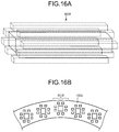
- FIG. 15A , FIG. 15B , FIG. 16A , and FIG. 16B are diagrams that illustrate a shim insertion cavity according to a different embodiment.
- the shim housing box for example, the shim pocket 110
- the shim housing box is formed into a shape to reduce the attractive force of the static magnetic field.
- Possible techniques for implementing the shape to reduce the attractive force of the static magnetic field that is applied to the shim housing box is roughly classified as the first technique for implementing a measure to the shim housing box itself, the second technique for implementing a measure to the shim insertion cavity itself into which the shim housing box is inserted, and the technique with the combination of the above.
- the first technique and the second technique with reference to FIG. 12 to FIG. 16B .
- shim housing box is designed to be inserted into one of the shim insertion cavities through one of the insertion openings.
- FIG. 12 per one shim insertion cavity 203 f , multiple shim housing boxes 210 are arranged side by side along the long axis direction of the substantially cylindrical hollow. This configuration corresponds to the typical shim pocket 110 that is explained in the first embodiment. Furthermore, FIG.
- the number of the shim housing boxes 210 that are arranged side by side in a long axis direction may be two, for example. That is, the number may be of any number.
- a plurality of the shim pockets 110 connected in advance, which are explained in the first embodiment, may be further arranged side by side in a long axis direction.
- the shape of the shim insertion cavity 203 f or the shim housing box 210 is not limited to the rectangle that is illustrated in FIG. 12 and, for example, the cylindrical shim housing box 210 may be inserted into the cylindrical shim insertion cavity 203 f.
- shim housing boxes 310 are arranged side by side in multiple columns, in a circumferential direction of the substantially cylindrical hollow.
- the shim-tray type shim housing box 310 that includes multiple pockets in a longitudinal direction is possible. As it is separated in a circumferential direction, the attractive force of the static magnetic field to the single shim housing box 310 is reduced.
- shim housing boxes 410 are arranged side by side in multiple columns, in a radial direction of the substantially cylindrical hollow.
- the shim-tray type shim housing box 410 that includes multiple pockets in a longitudinal direction is possible. As it is separated in a radial direction, the attractive force of the static magnetic field that is applied to the single shim housing box 410 is reduced.
- FIG. 12 illustrates the technique with which multiple shim housing boxes are arranged side by side in a long axis direction
- FIG. 13 illustrates the technique with which multiple shim housing boxes are arranged side by side in columns in a circumferential direction; however, they may be combined so that multiple shim housing boxes are arranged side by side in columns in a circumferential direction and are also arranged side by side in a long axis direction.
- multiple shim housing boxes may be arranged side by side in columns in a radial direction and also arranged side by side in a long axis direction.
- multiple shim housing boxes may be arranged side by side in columns in a circumferential direction and in a radial direction and also arranged side by side in a long axis direction. Multiple techniques are combined if necessary or the number of shim housing boxes arranged side by side is adjusted so that the configuration may be more suitable for a fine adjustment. In a case where an adjustment is made during maintenance while only one of the two insertion openings, which are formed on both ends in a long axis direction, is closed or opened, it typically can be said that the smaller the size of the single shim housing box that can be inserted through one of the insertion openings, the easier the fine adjustment is.
- the second technique is explained.
- the insertion openings of the shim insertion cavities penetrating through the entire length in a long axis direction are provided at multiple locations, and the shim housing box is inserted into the shim insertion cavity through the insertion opening.
- a group of insertion openings of the shim insertion cavities is provided at the locations scattered in a circumferential direction.
- This example corresponds to the shim-pocket insertion guide 103 f ′ that is explained in the second embodiment and that is formed such that it is separated into multiple tiers.
- two tiers of the upper tier and the lower tier are provided on an edge surface of the gradient coil 103 .
- a group shim insertion cavity 503 f is formed by putting together four shim insertion cavities in total, i.e., two in a vertical direction and two in a horizontal direction.
- the group of insertion openings is provided at each of the locations scattered in a circumferential direction. As the size of a single shim insertion cavity is smaller, it is considered that the attractive force of the static magnetic field that is applied to the shim housing box 310 , which is formed in accordance with the size of the shim insertion cavity, is reduced.
- FIG. 15A and FIG. 15B illustrate a case where the four shim insertion cavities 503 f are arranged in one piece; however, there is no limitation on the embodiment.
- the number of the shim insertion cavities 503 f that are arranged in one piece may be of any number.
- the shape of the shim insertion cavity 203 f is not limited to the rectangle that is illustrated in FIG. 15A and, for example, the cylindrical shim insertion cavity 503 f may be appropriate.
- a shim insertion cavity 603 f may be configured such that the main shim insertion cavity 603 f is surrounded by the sub shim insertion cavities 603 f .
- the roles, such as main or sub, may not be always divided, and the number of the shim insertion cavities 603 f that are arranged in one piece is of any number.
- the shape of the shim insertion cavity 603 f is not limited to the rectangle that is illustrated in FIG. 16A and, for example, the cylindrical shim insertion cavity 603 f may be appropriate.
- first technique and the second technique may be combined as appropriate.
- multiple shim housing boxes may be arranged side by side in a long axis direction or may be arranged side by side in columns in a circumferential direction or in a radial direction in one of the shim insertion cavities in the group that is explained as the second technique.
- an explanation is given of the technique for forming the cover for the insertion opening of the shim insertion cavity, the technique for connecting the shim housing boxes, or the like; however, they may be applied to the contents that are explained with reference to FIG. 12 to FIG. 16B .
Landscapes
- Health & Medical Sciences (AREA)
- Physics & Mathematics (AREA)
- Life Sciences & Earth Sciences (AREA)
- Nuclear Medicine, Radiotherapy & Molecular Imaging (AREA)
- Condensed Matter Physics & Semiconductors (AREA)
- General Physics & Mathematics (AREA)
- Molecular Biology (AREA)
- Heart & Thoracic Surgery (AREA)
- Veterinary Medicine (AREA)
- Biophysics (AREA)
- Pathology (AREA)
- Engineering & Computer Science (AREA)
- Biomedical Technology (AREA)
- Public Health (AREA)
- Medical Informatics (AREA)
- General Health & Medical Sciences (AREA)
- Surgery (AREA)
- Animal Behavior & Ethology (AREA)
- Radiology & Medical Imaging (AREA)
- High Energy & Nuclear Physics (AREA)
- Epidemiology (AREA)
- Magnetic Resonance Imaging Apparatus (AREA)
Abstract
Description
Claims (12)
Applications Claiming Priority (3)
| Application Number | Priority Date | Filing Date | Title |
|---|---|---|---|
| JP2013037379 | 2013-02-27 | ||
| JP2013-037379 | 2013-02-27 | ||
| PCT/JP2014/054969 WO2014133109A1 (en) | 2013-02-27 | 2014-02-27 | Magnetic resonance imaging device and gradient magnetic field coil |
Related Parent Applications (1)
| Application Number | Title | Priority Date | Filing Date |
|---|---|---|---|
| PCT/JP2014/054969 Continuation WO2014133109A1 (en) | 2013-02-27 | 2014-02-27 | Magnetic resonance imaging device and gradient magnetic field coil |
Publications (2)
| Publication Number | Publication Date |
|---|---|
| US20150362570A1 US20150362570A1 (en) | 2015-12-17 |
| US10578693B2 true US10578693B2 (en) | 2020-03-03 |
Family
ID=51428368
Family Applications (1)
| Application Number | Title | Priority Date | Filing Date |
|---|---|---|---|
| US14/836,210 Active 2036-04-16 US10578693B2 (en) | 2013-02-27 | 2015-08-26 | Magnetic resonance imaging apparatus and gradient coil |
Country Status (4)
| Country | Link |
|---|---|
| US (1) | US10578693B2 (en) |
| JP (1) | JP6309309B2 (en) |
| CN (1) | CN104968263B (en) |
| WO (1) | WO2014133109A1 (en) |
Cited By (1)
| Publication number | Priority date | Publication date | Assignee | Title |
|---|---|---|---|---|
| US11156683B2 (en) * | 2017-10-26 | 2021-10-26 | Canon Medical Systems Corporation | Static magnetic field adjustment device for magnetic resonance imaging apparatus and superconducting magnet |
Families Citing this family (12)
| Publication number | Priority date | Publication date | Assignee | Title |
|---|---|---|---|---|
| WO2014133109A1 (en) * | 2013-02-27 | 2014-09-04 | 株式会社東芝 | Magnetic resonance imaging device and gradient magnetic field coil |
| US10145925B2 (en) * | 2014-05-08 | 2018-12-04 | The Arizona Board Of Regents On Behalf Of The University Of Arizona | MRI with reconstruction of MR phase image |
| DE102014224446B4 (en) * | 2014-11-28 | 2018-12-20 | Siemens Healthcare Gmbh | Method for determining basic him settings of a magnetic resonance device |
| US10132882B2 (en) * | 2015-06-09 | 2018-11-20 | General Electric Company | Systems and methods for MRI body coil support structures |
| FR3050035B1 (en) * | 2016-04-11 | 2020-04-24 | Schneider Electric Industries Sas | ELECTRIC CURRENT MEASURING APPARATUS |
| US11054472B2 (en) * | 2017-08-23 | 2021-07-06 | Avo Multi-Amp Corporation | Relay test paddle |
| EP3457158A1 (en) * | 2017-09-19 | 2019-03-20 | Koninklijke Philips N.V. | Magnetic resonance imaging passive shim made of ferromagnetic material |
| EP3608929B1 (en) * | 2018-08-09 | 2020-09-30 | Siemens Healthcare GmbH | A directly coolable multifilament conductor means |
| US11202583B2 (en) * | 2019-02-07 | 2021-12-21 | Yale University | Magnetic resonance gradient accessory providing tailored gradients for diffusion encoding |
| CN114114114B (en) * | 2020-09-01 | 2024-07-19 | 西门子(深圳)磁共振有限公司 | Shimming assembly for gradient coil and magnetic resonance imaging device |
| CN115876363B (en) * | 2021-09-29 | 2025-04-29 | 西门子(深圳)磁共振有限公司 | Method and device for evaluating the static stress state of shim strips in a magnetic resonance system |
| EP4239355A1 (en) | 2022-03-01 | 2023-09-06 | Koninklijke Philips N.V. | Shim elements for use with a magnetic resonance apparatus |
Citations (13)
| Publication number | Priority date | Publication date | Assignee | Title |
|---|---|---|---|---|
| US4990877A (en) * | 1989-12-04 | 1991-02-05 | General Electric Company | Passive shimming assembly for MR magnet |
| US5635839A (en) * | 1994-11-04 | 1997-06-03 | Picker International, Inc. | High order passive shimming assembly for MRI magnets |
| US5786695A (en) * | 1997-03-21 | 1998-07-28 | Picker International, Inc. | Shim tray with reduced heat conduction and forced cooling |
| US20030222650A1 (en) * | 2002-03-28 | 2003-12-04 | Franz Boemmel | Shim tray, and gradient coils system and magnetic resonance apparatus for the acceptable of the shim tray |
| US20080191698A1 (en) | 2007-02-13 | 2008-08-14 | Kabushiki Kaisha Toshiba | MRI apparatus, NMR analyzer, and gantry |
| US20080290871A1 (en) | 2007-05-25 | 2008-11-27 | Mitsubishi Electric Corporation | Magnetic field adjustment device and magnetic field adjustment method for superconducting magnet |
| CN101334455A (en) | 2007-02-13 | 2008-12-31 | 株式会社东芝 | MRI apparatus, NMR analysis apparatus, and bench |
| US20100237867A1 (en) * | 2009-03-23 | 2010-09-23 | Siemens Plc. | Arrangements and Method for Shimming a Magnetic Field |
| US20100271028A1 (en) * | 2009-04-23 | 2010-10-28 | Hiromi Kawamoto | Magnetic resonance imaging apparatus |
| US20110006769A1 (en) | 2009-07-09 | 2011-01-13 | Iwasa Masateru | Magnetic resonance imaging apparatus and shimming apparatus |
| JP2012115474A (en) | 2010-11-30 | 2012-06-21 | Toshiba Corp | Mri apparatus |
| WO2012132911A1 (en) | 2011-03-25 | 2012-10-04 | 株式会社 日立メディコ | Method for adjusting static magnetic field homogeneity, static magnetic field generation device for magnetic resonance imaging, magnetic field adjustment system, and program |
| US20140061202A1 (en) * | 2012-09-05 | 2014-03-06 | General Electric Company | Warm bore cylinder assembly |
Family Cites Families (2)
| Publication number | Priority date | Publication date | Assignee | Title |
|---|---|---|---|---|
| JP2008183397A (en) * | 2007-01-05 | 2008-08-14 | Toshiba Corp | Magnetic resonance imaging system |
| WO2014133109A1 (en) * | 2013-02-27 | 2014-09-04 | 株式会社東芝 | Magnetic resonance imaging device and gradient magnetic field coil |
-
2014
- 2014-02-27 WO PCT/JP2014/054969 patent/WO2014133109A1/en not_active Ceased
- 2014-02-27 JP JP2014037093A patent/JP6309309B2/en active Active
- 2014-02-27 CN CN201480007076.5A patent/CN104968263B/en active Active
-
2015
- 2015-08-26 US US14/836,210 patent/US10578693B2/en active Active
Patent Citations (16)
| Publication number | Priority date | Publication date | Assignee | Title |
|---|---|---|---|---|
| US4990877A (en) * | 1989-12-04 | 1991-02-05 | General Electric Company | Passive shimming assembly for MR magnet |
| US5635839A (en) * | 1994-11-04 | 1997-06-03 | Picker International, Inc. | High order passive shimming assembly for MRI magnets |
| US5786695A (en) * | 1997-03-21 | 1998-07-28 | Picker International, Inc. | Shim tray with reduced heat conduction and forced cooling |
| US20030222650A1 (en) * | 2002-03-28 | 2003-12-04 | Franz Boemmel | Shim tray, and gradient coils system and magnetic resonance apparatus for the acceptable of the shim tray |
| US20080191698A1 (en) | 2007-02-13 | 2008-08-14 | Kabushiki Kaisha Toshiba | MRI apparatus, NMR analyzer, and gantry |
| CN101334455A (en) | 2007-02-13 | 2008-12-31 | 株式会社东芝 | MRI apparatus, NMR analysis apparatus, and bench |
| US20080290871A1 (en) | 2007-05-25 | 2008-11-27 | Mitsubishi Electric Corporation | Magnetic field adjustment device and magnetic field adjustment method for superconducting magnet |
| JP2008289703A (en) | 2007-05-25 | 2008-12-04 | Mitsubishi Electric Corp | Magnetic field adjusting device and magnetic field adjusting method for superconducting magnet |
| US20100237867A1 (en) * | 2009-03-23 | 2010-09-23 | Siemens Plc. | Arrangements and Method for Shimming a Magnetic Field |
| US20100271028A1 (en) * | 2009-04-23 | 2010-10-28 | Hiromi Kawamoto | Magnetic resonance imaging apparatus |
| US20110006769A1 (en) | 2009-07-09 | 2011-01-13 | Iwasa Masateru | Magnetic resonance imaging apparatus and shimming apparatus |
| CN101957438A (en) | 2009-07-09 | 2011-01-26 | 株式会社东芝 | MR imaging apparatus and pad device |
| JP2012115474A (en) | 2010-11-30 | 2012-06-21 | Toshiba Corp | Mri apparatus |
| WO2012132911A1 (en) | 2011-03-25 | 2012-10-04 | 株式会社 日立メディコ | Method for adjusting static magnetic field homogeneity, static magnetic field generation device for magnetic resonance imaging, magnetic field adjustment system, and program |
| US20140009152A1 (en) | 2011-03-25 | 2014-01-09 | Hitachi Medical Corporation | Method for adjusting static magnetic field homogeneity, static magnetic field generation device for magnetic resonance imaging, magnetic field adjustment system, and program |
| US20140061202A1 (en) * | 2012-09-05 | 2014-03-06 | General Electric Company | Warm bore cylinder assembly |
Non-Patent Citations (3)
| Title |
|---|
| Chinese office action dated May 16, 2017, in Patent Application No. CN 201480007076.5. |
| International Search Report for PCT/JP2014/054969, dated Mar. 25, 2014, 4 pages. |
| Written Opinion of the ISA for PCT/JP2014/054969, dated Mar. 25, 2014, 3 pages. |
Cited By (1)
| Publication number | Priority date | Publication date | Assignee | Title |
|---|---|---|---|---|
| US11156683B2 (en) * | 2017-10-26 | 2021-10-26 | Canon Medical Systems Corporation | Static magnetic field adjustment device for magnetic resonance imaging apparatus and superconducting magnet |
Also Published As
| Publication number | Publication date |
|---|---|
| CN104968263B (en) | 2018-11-30 |
| WO2014133109A1 (en) | 2014-09-04 |
| CN104968263A (en) | 2015-10-07 |
| US20150362570A1 (en) | 2015-12-17 |
| JP6309309B2 (en) | 2018-04-11 |
| JP2014193317A (en) | 2014-10-09 |
Similar Documents
| Publication | Publication Date | Title |
|---|---|---|
| US10578693B2 (en) | Magnetic resonance imaging apparatus and gradient coil | |
| US8575934B2 (en) | Magnetic resonance imaging apparatus and shimming apparatus with convex to concave layered stacking of shim plates | |
| US10281538B2 (en) | Warm bore cylinder assembly | |
| JP5060384B2 (en) | Magnetic field uniformity adjustment software, magnetic field uniformity adjustment method, magnet apparatus, and magnetic resonance imaging apparatus | |
| CN105324678B (en) | Shim system for MRI hybrid scanners | |
| US9753107B2 (en) | Magnetic resonance imaging (MRI) apparatus and manufacturing method thereof | |
| US20150338482A1 (en) | Magnetic resonance imaging device and gradient coil | |
| US10067202B2 (en) | Magnetic resonance imaging apparatus and gradient coil | |
| JP2019141226A (en) | Gradient magnetic field coil | |
| KR102038629B1 (en) | Magnetic resonance imaging and Positron Emission Tomapraphy System | |
| CN111315293B (en) | Static magnetic field adjustment equipment and superconducting magnets for nuclear magnetic resonance imaging equipment | |
| US20140125341A1 (en) | Gradient coil mounting unit and magnetic resonance imaging apparatus having the same | |
| JP5548374B2 (en) | Magnetic resonance imaging system and apparatus having multiple section magnets | |
| CN103327890B (en) | Gradient magnetic field coil device and magnetic resonance imaging device | |
| US20160109542A1 (en) | Gradient coil and magnetic resonance imaging device | |
| WO2023205746A3 (en) | Portable neonatal mri system and method | |
| CN104771169A (en) | Magnetic resonance imaging device and gasket tray | |
| JP7080746B2 (en) | Magnetic resonance imaging device | |
| US20100308831A1 (en) | Optimized flat/saddle coil cooling system | |
| JP2020006047A (en) | Magnetic resonance imaging system | |
| JP2014180446A (en) | Gradient magnetic field coil unit and magnetic resonance imaging apparatus | |
| JP6422739B2 (en) | Gradient coil and magnetic resonance imaging apparatus | |
| JP2014221159A (en) | Magnetic resonance imaging apparatus | |
| JP2005185787A (en) | Electromagnet apparatus and magnetic resonance imaging apparatus |
Legal Events
| Date | Code | Title | Description |
|---|---|---|---|
| AS | Assignment |
Owner name: TOSHIBA MEDICAL SYSTEMS CORPORATION, JAPAN Free format text: ASSIGNMENT OF ASSIGNORS INTEREST;ASSIGNORS:SAKAKURA, YOSHITOMO;NOGAMI, KAZUTO;TANAKA, HIDEKAZU;REEL/FRAME:036427/0248 Effective date: 20150805 Owner name: KABUSHIKI KAISHA TOSHIBA, JAPAN Free format text: ASSIGNMENT OF ASSIGNORS INTEREST;ASSIGNORS:SAKAKURA, YOSHITOMO;NOGAMI, KAZUTO;TANAKA, HIDEKAZU;REEL/FRAME:036427/0248 Effective date: 20150805 |
|
| AS | Assignment |
Owner name: TOSHIBA MEDICAL SYSTEMS CORPORATION, JAPAN Free format text: ASSIGNMENT OF ASSIGNORS INTEREST;ASSIGNOR:KABUSHIKI KAISHA TOSHIBA;REEL/FRAME:038831/0922 Effective date: 20160316 |
|
| STPP | Information on status: patent application and granting procedure in general |
Free format text: FINAL REJECTION MAILED |
|
| STPP | Information on status: patent application and granting procedure in general |
Free format text: NON FINAL ACTION MAILED |
|
| STPP | Information on status: patent application and granting procedure in general |
Free format text: NOTICE OF ALLOWANCE MAILED -- APPLICATION RECEIVED IN OFFICE OF PUBLICATIONS |
|
| STPP | Information on status: patent application and granting procedure in general |
Free format text: PUBLICATIONS -- ISSUE FEE PAYMENT RECEIVED |
|
| STCF | Information on status: patent grant |
Free format text: PATENTED CASE |
|
| MAFP | Maintenance fee payment |
Free format text: PAYMENT OF MAINTENANCE FEE, 4TH YEAR, LARGE ENTITY (ORIGINAL EVENT CODE: M1551); ENTITY STATUS OF PATENT OWNER: LARGE ENTITY Year of fee payment: 4 |