US10570950B2 - Spherical joint assembly with a spherical bearing between integral collars - Google Patents
Spherical joint assembly with a spherical bearing between integral collars Download PDFInfo
- Publication number
- US10570950B2 US10570950B2 US15/161,895 US201615161895A US10570950B2 US 10570950 B2 US10570950 B2 US 10570950B2 US 201615161895 A US201615161895 A US 201615161895A US 10570950 B2 US10570950 B2 US 10570950B2
- Authority
- US
- United States
- Prior art keywords
- collar
- bearing
- spherical
- radial outer
- mounts
- Prior art date
- Legal status (The legal status is an assumption and is not a legal conclusion. Google has not performed a legal analysis and makes no representation as to the accuracy of the status listed.)
- Active, expires
Links
Images


Classifications
-
- F—MECHANICAL ENGINEERING; LIGHTING; HEATING; WEAPONS; BLASTING
- F16—ENGINEERING ELEMENTS AND UNITS; GENERAL MEASURES FOR PRODUCING AND MAINTAINING EFFECTIVE FUNCTIONING OF MACHINES OR INSTALLATIONS; THERMAL INSULATION IN GENERAL
- F16C—SHAFTS; FLEXIBLE SHAFTS; ELEMENTS OR CRANKSHAFT MECHANISMS; ROTARY BODIES OTHER THAN GEARING ELEMENTS; BEARINGS
- F16C11/00—Pivots; Pivotal connections
- F16C11/04—Pivotal connections
- F16C11/045—Pivotal connections with at least a pair of arms pivoting relatively to at least one other arm, all arms being mounted on one pin
-
- F—MECHANICAL ENGINEERING; LIGHTING; HEATING; WEAPONS; BLASTING
- F16—ENGINEERING ELEMENTS AND UNITS; GENERAL MEASURES FOR PRODUCING AND MAINTAINING EFFECTIVE FUNCTIONING OF MACHINES OR INSTALLATIONS; THERMAL INSULATION IN GENERAL
- F16C—SHAFTS; FLEXIBLE SHAFTS; ELEMENTS OR CRANKSHAFT MECHANISMS; ROTARY BODIES OTHER THAN GEARING ELEMENTS; BEARINGS
- F16C11/00—Pivots; Pivotal connections
- F16C11/04—Pivotal connections
- F16C11/06—Ball-joints; Other joints having more than one degree of angular freedom, i.e. universal joints
- F16C11/0604—Construction of the male part
-
- F—MECHANICAL ENGINEERING; LIGHTING; HEATING; WEAPONS; BLASTING
- F16—ENGINEERING ELEMENTS AND UNITS; GENERAL MEASURES FOR PRODUCING AND MAINTAINING EFFECTIVE FUNCTIONING OF MACHINES OR INSTALLATIONS; THERMAL INSULATION IN GENERAL
- F16C—SHAFTS; FLEXIBLE SHAFTS; ELEMENTS OR CRANKSHAFT MECHANISMS; ROTARY BODIES OTHER THAN GEARING ELEMENTS; BEARINGS
- F16C11/00—Pivots; Pivotal connections
- F16C11/04—Pivotal connections
- F16C11/06—Ball-joints; Other joints having more than one degree of angular freedom, i.e. universal joints
- F16C11/0614—Ball-joints; Other joints having more than one degree of angular freedom, i.e. universal joints the female part of the joint being open on two sides
-
- F—MECHANICAL ENGINEERING; LIGHTING; HEATING; WEAPONS; BLASTING
- F16—ENGINEERING ELEMENTS AND UNITS; GENERAL MEASURES FOR PRODUCING AND MAINTAINING EFFECTIVE FUNCTIONING OF MACHINES OR INSTALLATIONS; THERMAL INSULATION IN GENERAL
- F16C—SHAFTS; FLEXIBLE SHAFTS; ELEMENTS OR CRANKSHAFT MECHANISMS; ROTARY BODIES OTHER THAN GEARING ELEMENTS; BEARINGS
- F16C11/00—Pivots; Pivotal connections
- F16C11/04—Pivotal connections
- F16C11/06—Ball-joints; Other joints having more than one degree of angular freedom, i.e. universal joints
- F16C11/0685—Manufacture of ball-joints and parts thereof, e.g. assembly of ball-joints
-
- F—MECHANICAL ENGINEERING; LIGHTING; HEATING; WEAPONS; BLASTING
- F16—ENGINEERING ELEMENTS AND UNITS; GENERAL MEASURES FOR PRODUCING AND MAINTAINING EFFECTIVE FUNCTIONING OF MACHINES OR INSTALLATIONS; THERMAL INSULATION IN GENERAL
- F16C—SHAFTS; FLEXIBLE SHAFTS; ELEMENTS OR CRANKSHAFT MECHANISMS; ROTARY BODIES OTHER THAN GEARING ELEMENTS; BEARINGS
- F16C11/00—Pivots; Pivotal connections
- F16C11/04—Pivotal connections
- F16C11/06—Ball-joints; Other joints having more than one degree of angular freedom, i.e. universal joints
- F16C11/0695—Mounting of ball-joints, e.g. fixing them to a connecting rod
-
- F—MECHANICAL ENGINEERING; LIGHTING; HEATING; WEAPONS; BLASTING
- F16—ENGINEERING ELEMENTS AND UNITS; GENERAL MEASURES FOR PRODUCING AND MAINTAINING EFFECTIVE FUNCTIONING OF MACHINES OR INSTALLATIONS; THERMAL INSULATION IN GENERAL
- F16C—SHAFTS; FLEXIBLE SHAFTS; ELEMENTS OR CRANKSHAFT MECHANISMS; ROTARY BODIES OTHER THAN GEARING ELEMENTS; BEARINGS
- F16C2326/00—Articles relating to transporting
- F16C2326/43—Aeroplanes; Helicopters
-
- F—MECHANICAL ENGINEERING; LIGHTING; HEATING; WEAPONS; BLASTING
- F16—ENGINEERING ELEMENTS AND UNITS; GENERAL MEASURES FOR PRODUCING AND MAINTAINING EFFECTIVE FUNCTIONING OF MACHINES OR INSTALLATIONS; THERMAL INSULATION IN GENERAL
- F16C—SHAFTS; FLEXIBLE SHAFTS; ELEMENTS OR CRANKSHAFT MECHANISMS; ROTARY BODIES OTHER THAN GEARING ELEMENTS; BEARINGS
- F16C2360/00—Engines or pumps
- F16C2360/23—Gas turbine engines
Definitions
- This disclosure relates generally to a moveable joint and, more particularly, to a spherical joint assembly for pivotally coupling components together.
- a bearing joint assembly includes a bearing sleeve, a first mount, a pair of second mounts and a fastener.
- the bearing sleeve extends axially along a centerline and includes a spherical bearing, a first collar and a second collar.
- the spherical bearing is axially between the first collar and the second collar.
- An annular channel is formed by and extends axially between the spherical bearing and the first collar.
- the first mount is mounted on and slidably engages the spherical bearing.
- the bearing sleeve is axially between the second mounts.
- the fastener projects through the bearing sleeve and secures the bearing sleeve to the second mounts.
- another bearing joint assembly includes a bearing sleeve, a first mount, a pair of second mounts and a fastener.
- the bearing sleeve extends axially along a centerline and includes a spherical bearing, a first collar and a second collar.
- the spherical bearing is axially between the first collar and the second collar.
- the spherical bearing includes a radial outer spherical surface with a minimum radius value.
- the first collar includes a radial outer collar surface with a maximum radius value that is greater than the minimum radius value of the radial outer spherical surface.
- the first mount is mounted on and slidably engages the radial outer spherical surface.
- the bearing sleeve is axially between the second mounts.
- the fastener projects through the bearing sleeve and secures the bearing sleeve to the second mounts.
- another bearing joint assembly includes a bearing sleeve and a linkage.
- the bearing sleeve extends axially along a centerline and includes a spherical bearing, a first collar and a second collar.
- the spherical bearing is axially between the first collar and the second collar.
- An annular channel is formed by and extends axially between the spherical bearing and the first collar.
- At least the spherical bearing and the first collar are included in a monolithic body.
- the linkage includes a first mount slidably engaged with the spherical bearing. The spherical bearing is captured within an aperture extending axially through the first mount.
- the annular channel may be a first annular channel.
- a second annular channel may be formed by and extend axially between the spherical bearing and the second collar.
- the bearing sleeve may be a monolithic body.
- the spherical bearing may include a radial outer spherical surface with a minimum radius value.
- the first collar may include a radial outer collar surface with a maximum radius value that is greater than the minimum radius value of the radial outer spherical surface.
- the radial outer spherical surface may have a maximum radius value.
- the maximum radius value of the radial outer collar surface may be less than or equal to the maximum radius value of the radial outer spherical surface.
- the first collar may include a radial outer collar surface. At least a portion of the radial outer collar surface may taper radially inwards as the first collar extends axially towards the spherical bearing.
- the at least a portion of the radial outer collar surface may have a generally conical geometry.
- the at least a portion of the radial outer collar surface may be a first portion.
- a second portion of the radial outer collar surface may have a cylindrical geometry.
- the bearing joint assembly may include a strut and a turbine engine component.
- the strut may include the first mount.
- the turbine engine component may include the second mounts.
- An annular channel may be formed by and extend axially between the spherical bearing and the first collar.
- the first collar may include a radial outer collar surface. At least a portion of the radial outer collar surface may taper radially inwards as the first collar extends axially towards the spherical bearing.
- FIG. 1 is a partial, side sectional illustration of a spherical bearing joint assembly.
- FIG. 2 is a side sectional illustration of a bearing sleeve.
- FIG. 3 is a partial, side sectional illustration of the spherical bearing joint assembly depicting articulation of a first mount relative to second mounts.
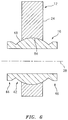
- FIGS. 4 to 6 illustrate a sequence depicting mounting of a first mount on a spherical bearing.
- FIG. 7 is a side sectional illustration of another bearing sleeve.
- FIG. 1 illustrates a bearing joint assembly 10 .
- This bearing joint assembly 10 is configured to provide a spherical bearing joint between two components 12 and 14 , which enables generally spherical pivoting movement between the components 12 and 14 .
- Such a bearing joint assembly may be configured for an aeronautical, industrial or other gas turbine engine application.
- the first component 12 may be an actuation linkage (e.g., a strut) for actuating movement of another component of the gas turbine engine; e.g., a component of a variable exhaust nozzle, a variable vane, etc.
- the bearing joint assembly 10 of the present disclosure is not limited to such exemplary component configurations, or to gas turbine engine applications.
- the bearing joint assembly 10 in particular, can be configured for use in any application where a joint moveably (or statically) couples two components together.
- the bearing joint assembly 10 of FIG. 1 includes the first component 12 , the second component 14 , a bearing sleeve 16 and a fastener 18 , which may include a bolt 20 and a nut 22 (or any other type of pin and retainer).
- the bearing joint assembly 10 also includes at least a first mount 24 (e.g., a flange or tab) and two or more (shown as a pair in FIG. 1 ) of second mounts 26 A and 26 B (e.g., a flange or tab).
- the first component 12 may include the first mount 24 .
- the first mount 24 may be configured as a distal flange/tab/tongue of the first component 12 ; e.g., the actuation linkage.
- the first mount 24 may be formed discrete from and subsequently attached (e.g., mechanically fastened and/or bonded) to the first component 12 .
- the second component 14 may include the second mounts 26 A and 26 B.
- the second mounts 26 A and 26 B may be configured as tabs/flanges projecting out from the second component 14 ; e.g., the turbine engine component.
- one or more of the second mounts 26 A and 26 B may each be formed discrete from and subsequently attached to the second component 14 .
- the bearing sleeve 16 extends axially along a centerline 28 between opposing first and second axial ends 30 and 32 .
- the bearing sleeve 16 extends radially out from an inner periphery 34 to an outer periphery 36 , where an inner sleeve surface 38 at the inner periphery 34 forms a bore 40 axially through the bearing sleeve 16 .
- the bearing sleeve 16 also extends circumferentially around the centerline 28 , thereby providing the bearing sleeve 16 with a generally tubular geometry.
- the bearing sleeve 16 includes a spherical bearing 42 and one or more collars 44 and 46 .
- the bearing sleeve 16 of FIG. 2 is formed as a monolithic body from material such as, but not limited to, metal, polymer, composite, etc.
- all portions 42 , 44 and 46 of the bearing sleeve 16 may be formed (e.g., cast, machined, additively manufactured, etc.) integral with one another as a single unit.
- none of the bearing sleeve portions 42 , 44 and 46 are discretely formed elements and then (e.g., mechanically) attached to one another.
- the present disclosure is not limited to such an exemplary monolithic bearing sleeve body embodiment.
- one of the collars 44 or 46 can be formed discrete from and subsequently attached to the bearing sleeve 16 .
- the spherical bearing 42 is disposed and extends axially between the first collar 44 and the second collar 46 .
- the spherical bearing 42 extends radially out from the inner sleeve surface 38 to a radial outer spherical surface 48 (e.g., a spherical bearing surface) at the outer periphery 36 .
- This spherical surface 48 extends axially between a first end 50 and a second end 52 , where the first end 50 is adjacent (or in close proximity to) the first collar 44 and the second end 52 is adjacent (or in close proximity to) the second collar 46 .
- the spherical surface 48 extends circumferentially around the centerline 28 .
- a radius 54 of the spherical surface 48 changes as the spherical surface 48 axially extends between the first end 50 and the second end 52 to provide the spherical surface 48 with a circular side sectional geometry; see FIG. 2 .
- the radius 54 has a first minimum radius value (e.g., left hand side minimum radius value) at the first end 50 .
- the radius 54 has a second minimum radius value (e.g., right hand side minimum radius value) at the second end 52 , which second minimum radius value may be approximately equal to the first minimum radius value.
- the radius 54 has a maximum radius value (e.g., a peak value) that is greater than the first minimum radius value and the second minimum radius value.
- a maximum radius value e.g., a peak value
- minimum may describe an axial point where the radius 54 has the smallest value towards a respective side of a peak; e.g., the intermediate point 56 .
- maximum may describe an axial point (peak point) where the radius 54 has the largest value; e.g., at the intermediate point 56 .
- the first collar 44 is disposed at (e.g., on, adjacent or proximate) the first axial end 30 .
- the first collar 44 of FIG. 2 forms a first end surface 58 at the first axial end 30 .
- the first collar 44 extends radially out from the inner sleeve surface 38 to a radial outer collar surface 60 at the outer periphery 36 .
- This collar surface 60 extends axially from the first end surface 58 at the first axial end 30 to (and may be contiguous with) the first end 50 of the spherical surface 48 .
- the collar surface 60 extends circumferentially around the centerline 28 .
- a radius 62 of the collar surface 60 may change as the collar surface 60 axially extends from the first axial end 30 to the spherical bearing 42 to provide the collar surface 60 with a radially tapering side sectional geometry.
- the collar surface 60 of FIG. 2 includes a first portion 64 and a second portion 66 .
- the first portion 64 may have a substantially cylindrical geometry, where the radius 62 is substantially constant.
- the second portion 66 may have a substantially conical geometry, which radially tapers (e.g., the radius 62 decreases) as the second portion 66 extends axially from the first portion 64 to the spherical surface 48 .
- the radius 62 of the first portion 64 has a maximum radius value and the radius 62 of the second portion 66 adjacent the spherical surface 48 has a minimum radius value, which minimum radius value is substantially equal to the first minimum radius value of the radius 54 .
- the maximum radius value of the radius 62 is greater than the first minimum radius value of the radius 54 .
- the maximum radius value of the radius 62 is less than (or may be substantially equal) the maximum radius value of the radius 54 , which may facilitate assembly of the spherical bearing 42 with the first mount 24 as described below.
- the first collar 44 and the spherical bearing 42 collectively form a first annular channel 68 .
- This first annular channel 68 is formed by and extends axially between the collar surface 60 and the spherical surface 48 .
- the first annular channel 68 extends radially into the bearing sleeve 16 (towards the centerline 28 ) to an intersection (e.g., trough point) between the first collar 44 and the spherical bearing 42 .
- the first annular channel 68 extends circumferentially around the centerline 28 through the bearing sleeve 16 .
- This first annular channel 68 provides space for the first mount 24 to pivot about the spherical bearing 42 and, for example, freely articulate between the second mounts 26 A and 26 B as shown in FIG. 3 .
- the first collar 44 of FIG. 3 therefore is configured (e.g., sized and shaped) to enable unobstructed movement of the first mount 24 by the first collar 44 .
- movement of the first mount 24 may be obstructed by other elements such as the second mounts 26 A and 26 B.
- the second collar 46 is disposed at (e.g., on, adjacent or proximate) the second axial end 32 .
- the second collar 46 of FIG. 2 forms a second end surface 70 at the second axial end 32 .
- the second collar 46 extends radially out from the inner sleeve surface 38 to a radial outer collar surface 72 at the outer periphery 36 .
- This collar surface 72 extends axially from the second end surface 70 at the second axial end 32 to (and may be contiguous with) the second end 52 of the spherical surface 48 .
- the collar surface 72 extends circumferentially around the centerline 28 .
- a radius 74 of the collar surface 72 may change as the collar surface 72 axially extends from the second axial end 32 to the spherical bearing 42 to provide the collar surface 72 with a radially tapering side sectional geometry.
- the collar surface 72 of FIG. 2 includes a first portion 76 and a second portion 78 .
- the first portion 76 may have a substantially cylindrical geometry, where the radius 74 is substantially constant.
- the second portion 78 may have a substantially conical geometry, which radially tapers (e.g., the radius 74 decreases) as the second portion 78 extends axially from the first portion 76 to the spherical surface 48 .
- the radius 74 of the first portion 76 has a maximum radius value and the radius 74 of the second portion 78 adjacent the spherical surface 48 has a minimum radius value, which minimum radius value is substantially equal to the first minimum radius value of the radius 54 .
- the maximum radius value of the radius 74 is greater than the first minimum radius value of the radius 54 .
- the maximum radius value of the radius 74 is less than (or may be substantially equal) the maximum radius value of the radius 54 , which may facilitate assembly of the spherical bearing 42 with the first mount 24 as described below.
- the second collar 46 and the spherical bearing 42 collectively form a second annular channel 80 .
- This second annular channel 80 is formed by and extends axially between the collar surface 72 and the spherical surface 48 .
- the second annular channel 80 extends radially into the bearing sleeve 16 (towards the centerline 28 ) to an intersection (e.g., trough point) between the second collar 46 and the spherical bearing 42 .
- the second annular channel 80 extends circumferentially around the centerline 28 through the bearing sleeve 16 .
- This second annular channel 80 provides space for the first mount 24 to pivot about the spherical bearing 42 and, for example, freely articulate between the second mounts 26 A and 26 B as shown in FIG.
- the second collar 46 of FIG. 3 therefore is configured (e.g., sized and shaped) to enable unobstructed movement of the first mount 24 by the second collar 46 .
- movement of the first mount 24 may be obstructed by other elements such as the second mounts 26 A and 26 B.
- the first collar 44 and the second collar 46 of FIGS. 2 and 3 are illustrated with substantially mirror image configurations; e.g., geometry (shapes), sizes, etc.
- the bearing sleeve 16 of the present disclosure is not limited to such an exemplary embodiment.
- one of the collars 44 , 46 may have a different configuration (e.g., geometry and/or size) than the other.
- FIGS. 4 to 6 illustrate a sequence depicting the mounting of the first mount 24 on the spherical bearing 42 .
- the maximum radius value of the radius 62 , 74 of at least one of the collars 44 , 46 is sized to be less than (or equal to) the maximum radius value of the radius 54 of the spherical bearing 42 such that the collar 44 , 46 may pass through a bearing aperture 82 in the first mount 24 .
- This enables the spherical bearing 42 to be arranged within the bearing aperture 82 as shown in FIG. 5 .
- the first mount 24 may then be swaged to capture the spherical bearing 42 within the bearing aperture 82 .
- FIG. 1 the maximum radius value of the radius 62 , 74 of at least one of the collars 44 , 46 is sized to be less than (or equal to) the maximum radius value of the radius 54 of the spherical bearing 42 such that the collar 44 , 46 may pass through a bearing aperture 82 in the first mount 24
- the spherical surface 48 engages (e.g., contacts) a surface 84 of the first mount 24 that forms the bearing aperture 82 , which enables the first mount 24 to slide on the spherical surface 48 and pivot relative to the bearing sleeve 16 .
- the bearing sleeve 16 is disposed axially between the second mounts 26 A and 26 B after the first mount 24 is mounted to the spherical bearing 42 .
- the first collar 44 is disposed axially next to (and may axially engage) the second mount 26 A.
- the second collar 46 is disposed axially next to (and may axially engage) the second mount 26 B.
- the bolt 20 is inserted sequentially through mounting apertures ( 88 , 40 and 90 ) respectively in the second mount 26 B, the bearing sleeve 16 and the second mount 26 A.
- the nut 22 is threaded onto an end of the bolt 20 , thereby securing the bearing sleeve 16 and, thus, the first mount 24 with the second mounts 26 A and 26 B.
- the first mount 24 may pivot about the spherical bearing 42 as illustrated in FIG. 3 .
- the bearing joint assembly 10 may also transfer loads between the first component 12 and the second component 14 .
- the bearing joint assembly 10 may be in compression where the mounts 24 and 26 A-B push towards one another.
- the bearing joint assembly 10 may be in tension where the mounts 24 and 26 A-B pull away from one another.
- the bolt 20 may have a tendency to bend. Such bending subjects the spherical bearing 42 to a compressive load whereas the collars 44 and 46 are subjected to tensile loads.
- the collars 44 and 46 are sized with relatively large radiuses 62 and 74 (see FIG. 2 ); e.g., where the maximum radius values of the radiuses 62 and 74 is greater than the minimum radius values of the radius 54 .
- the bearing sleeve 16 of the present disclosure may have various configurations different than that specifically described above.
- at least a portion of the collar surface 60 , 72 is configured with a generally spherical geometry.
- at least a portion of the collar surface 60 , 72 may have a complex (e.g., splined and/or compound) geometry.
- the collar 44 , 46 may be separated from the spherical bearing 42 by a slight gap; e.g., a spacer 92 , 94 .
- the first mount 24 is described above as being swaged on the spherical bearing 42 . However, in other embodiments, other methodologies may also or alternatively be used to capture the spherical bearing 42 within the bearing aperture 82 . For example, one or more bearing caps may be attached to sides of the first mount 24 after the spherical bearing 42 is positioned within the bearing aperture 82 .
Landscapes
- Engineering & Computer Science (AREA)
- General Engineering & Computer Science (AREA)
- Mechanical Engineering (AREA)
- Support Of The Bearing (AREA)
- Sliding-Contact Bearings (AREA)
Abstract
Description
Claims (9)
Priority Applications (2)
| Application Number | Priority Date | Filing Date | Title |
|---|---|---|---|
| US15/161,895 US10570950B2 (en) | 2016-05-23 | 2016-05-23 | Spherical joint assembly with a spherical bearing between integral collars |
| EP17172078.2A EP3249248B1 (en) | 2016-05-23 | 2017-05-19 | Spherical joint assembly with a spherical bearing between collars |
Applications Claiming Priority (1)
| Application Number | Priority Date | Filing Date | Title |
|---|---|---|---|
| US15/161,895 US10570950B2 (en) | 2016-05-23 | 2016-05-23 | Spherical joint assembly with a spherical bearing between integral collars |
Publications (2)
| Publication Number | Publication Date |
|---|---|
| US20170335885A1 US20170335885A1 (en) | 2017-11-23 |
| US10570950B2 true US10570950B2 (en) | 2020-02-25 |
Family
ID=58738989
Family Applications (1)
| Application Number | Title | Priority Date | Filing Date |
|---|---|---|---|
| US15/161,895 Active 2038-11-04 US10570950B2 (en) | 2016-05-23 | 2016-05-23 | Spherical joint assembly with a spherical bearing between integral collars |
Country Status (2)
| Country | Link |
|---|---|
| US (1) | US10570950B2 (en) |
| EP (1) | EP3249248B1 (en) |
Cited By (1)
| Publication number | Priority date | Publication date | Assignee | Title |
|---|---|---|---|---|
| US11732654B2 (en) | 2021-03-19 | 2023-08-22 | General Electric Company | Feed-through assembly |
Families Citing this family (1)
| Publication number | Priority date | Publication date | Assignee | Title |
|---|---|---|---|---|
| US10634092B2 (en) | 2017-09-08 | 2020-04-28 | United Technologies Corporation | Linkage assembly preventing axial rotation of the link rod |
Citations (52)
| Publication number | Priority date | Publication date | Assignee | Title |
|---|---|---|---|---|
| US1466756A (en) | 1921-10-27 | 1923-09-04 | George R Rich | Connecting means between motor pistons and connecting rods |
| US1943364A (en) | 1933-03-27 | 1934-01-16 | Charles F Betz | Piston pin assembly |
| US2066695A (en) | 1934-07-23 | 1937-01-05 | Houde Eng Corp | Joint |
| US3161185A (en) | 1962-11-07 | 1964-12-15 | Justinien Marcel | Elastically connected pistons for the automatic adjustment of volumetric compression rations |
| US3831888A (en) * | 1972-07-27 | 1974-08-27 | Mc Donnell Douglas Corp | Aircraft engine suspension system |
| US3832022A (en) | 1973-04-30 | 1974-08-27 | Caterpillar Tractor Co | Dual seal arrangement for a spherical joint |
| US4065077A (en) * | 1976-04-30 | 1977-12-27 | Rolls-Royce Limited | Attachment for attaching jet propulsion engines to fixed structure |
| US4232563A (en) | 1978-03-16 | 1980-11-11 | Barry Wright Corporation | Laminated elastomeric end bearings for articulating links |
| US4243192A (en) | 1978-12-04 | 1981-01-06 | Mcdonnell Douglas Corporation | Ball pivot thrust bearing flex joint |
| GB1585795A (en) | 1976-07-16 | 1981-03-11 | Bos Kalis Westminster | Dredger chain joint |
| US4889458A (en) | 1987-09-18 | 1989-12-26 | British Aerospace, Plc | Lock nut assemblies |
| US4943013A (en) | 1988-09-01 | 1990-07-24 | Societe Nationale D'etude Et De Construction De Moteurs D-Aviation (Snecma) | Fastener system for a jet engine mounting |
| US5120195A (en) | 1990-10-23 | 1992-06-09 | Schmaling David N | Clevis joint capable of accommodating substantial pivotal motion between its joined members and loading along its axis |
| US5245823A (en) | 1991-09-23 | 1993-09-21 | United Technologies Corporation | External flap vectoring mechanism |
| US5251986A (en) | 1992-08-10 | 1993-10-12 | Grumman Aerospace Corporation | Bushing assembly |
| US5523530A (en) | 1994-07-25 | 1996-06-04 | United Technologies Corporation | Elastomeric acoustic insulator |
| EP0760433A2 (en) | 1995-08-22 | 1997-03-05 | The Torrington Company | Spherical plain bearing with a locking device |
| US5649417A (en) | 1995-03-24 | 1997-07-22 | The Boeing Company | Fail-safe engine mount system |
| US5931597A (en) | 1997-10-16 | 1999-08-03 | Trw Inc. | Ball joint |
| US6173919B1 (en) | 1998-02-04 | 2001-01-16 | Aerospatiale Societe Nationale Industrielle | Attachment device for an aircraft engine |
| US20050281611A1 (en) | 2004-06-17 | 2005-12-22 | Seals-It | Seal component for use with a spherical rod end assembly |
| US20060088371A1 (en) | 2004-09-28 | 2006-04-27 | Solar Turbines Incorporated | Low profile gimbal |
| US20070122232A1 (en) | 2005-11-28 | 2007-05-31 | Tomasz Buchner | Ball joint assembly |
| US20070189649A1 (en) | 2006-02-16 | 2007-08-16 | The Boeing Company | Lightweight bearing cartridge for wear application |
| DE102007016171A1 (en) | 2007-04-02 | 2008-10-09 | Zf Friedrichshafen Ag | Ball sleeve joint |
| US7438493B2 (en) | 2005-11-03 | 2008-10-21 | ZF Lemförder Metallwaren AG | Cross axis ball and socket joint with sealing ring for cross axis sleeve ends |
| US20090016809A1 (en) * | 2005-07-28 | 2009-01-15 | Reinhard Buhl | Joint arrangement |
| US7594794B2 (en) | 2006-08-24 | 2009-09-29 | United Technologies Corporation | Leaned high pressure compressor inlet guide vane |
| US7654766B2 (en) | 2001-07-13 | 2010-02-02 | Audi | Ball joint |
| US7753612B2 (en) | 2006-10-13 | 2010-07-13 | Snecma | Swiveling device for a bell crank fork |
| US20100215426A1 (en) | 2009-02-25 | 2010-08-26 | Caterpillar Inc. | Machine suspension link pin retention system |
| US7845176B2 (en) | 2007-03-20 | 2010-12-07 | United Technologies Corporation | Mode strut and divergent flap interface |
| US8002489B2 (en) * | 2004-02-25 | 2011-08-23 | Snecma | Shock absorber in elastomer material for a suspension connecting rod or other connecting component |
| US20110293360A1 (en) | 2010-05-28 | 2011-12-01 | Caterpillar, Inc. | Seal Assembly and Method for Forming a Seal Assembly |
| US20130114995A1 (en) | 2011-11-07 | 2013-05-09 | Eurocopter | Ball-joint mechanism between a clevis and a connecting rod, in particular for control apparatus of a rotorcraft |
| US20130328284A1 (en) * | 2012-06-06 | 2013-12-12 | Federal-Mogul Products, Inc. | Control arm with socket |
| US8740136B2 (en) | 2005-06-29 | 2014-06-03 | Airbus Operations Sas | Engine mount for an aircraft, to be placed between an engine and an engine mounting structure |
| US8851417B2 (en) | 2012-08-07 | 2014-10-07 | United Technologies Corporation | Self-retaining shear pin for blind mount location |
| US20140360152A1 (en) | 2013-03-21 | 2014-12-11 | United Technologies Corporation | Oil tank mount with yoke |
| US20150016965A1 (en) | 2013-07-15 | 2015-01-15 | United Technologies Corporation | Link arm drag reducing device |
| US9133768B2 (en) | 2012-08-21 | 2015-09-15 | United Technologies Corporation | Liner bracket for gas turbine engine |
| US20150322998A1 (en) | 2012-06-29 | 2015-11-12 | Iljin.Co.Ltd. | Ball Joint |
| US20150337891A1 (en) | 2013-01-11 | 2015-11-26 | United Technologies Corporation | Linkage with spherical or journal bearing assembly |
| US20160083101A1 (en) | 2013-09-19 | 2016-03-24 | United Technologies Corporation | Aircraft engine case shock mount |
| US9327570B2 (en) | 2014-03-04 | 2016-05-03 | Federal-Mogul Motorparts Corporation | Ball joint assembly for a control arm |
| US9592917B2 (en) * | 2013-12-12 | 2017-03-14 | Airbus Operations (Sas) | Assembly comprising an articulation spindle supported by a clevis and immobilized in translation by a blocking device integrating a double anti-rotation system |
| US9593708B2 (en) * | 2013-12-12 | 2017-03-14 | Airbus Operations (Sas) | Assembly comprising an articulation spindle supported by a clevis and immobilized in translation by a blocking device integrating a double anti-rotation system |
| US20170102026A1 (en) | 2014-05-21 | 2017-04-13 | Safran Aircraft Engines | Ball joint device for a turbine engine |
| US20170146126A1 (en) | 2015-11-25 | 2017-05-25 | Caterpillar Inc. | Circumferential Debris Seal for Pinned Joints |
| US9676489B2 (en) | 2014-10-30 | 2017-06-13 | Airbus Operations Sas | Aircraft engine attachment device, and corresponding aircraft |
| US9874146B2 (en) * | 2011-10-25 | 2018-01-23 | Siemens Aktiengesellschaft | Gas turbine engine support strut assembly |
| US9925838B2 (en) | 2014-03-04 | 2018-03-27 | Federal-Mogul Motorparts Llc | Ball joint assembly for a control arm |
-
2016
- 2016-05-23 US US15/161,895 patent/US10570950B2/en active Active
-
2017
- 2017-05-19 EP EP17172078.2A patent/EP3249248B1/en active Active
Patent Citations (53)
| Publication number | Priority date | Publication date | Assignee | Title |
|---|---|---|---|---|
| US1466756A (en) | 1921-10-27 | 1923-09-04 | George R Rich | Connecting means between motor pistons and connecting rods |
| US1943364A (en) | 1933-03-27 | 1934-01-16 | Charles F Betz | Piston pin assembly |
| US2066695A (en) | 1934-07-23 | 1937-01-05 | Houde Eng Corp | Joint |
| US3161185A (en) | 1962-11-07 | 1964-12-15 | Justinien Marcel | Elastically connected pistons for the automatic adjustment of volumetric compression rations |
| US3831888A (en) * | 1972-07-27 | 1974-08-27 | Mc Donnell Douglas Corp | Aircraft engine suspension system |
| US3832022A (en) | 1973-04-30 | 1974-08-27 | Caterpillar Tractor Co | Dual seal arrangement for a spherical joint |
| US4065077A (en) * | 1976-04-30 | 1977-12-27 | Rolls-Royce Limited | Attachment for attaching jet propulsion engines to fixed structure |
| GB1585795A (en) | 1976-07-16 | 1981-03-11 | Bos Kalis Westminster | Dredger chain joint |
| US4232563A (en) | 1978-03-16 | 1980-11-11 | Barry Wright Corporation | Laminated elastomeric end bearings for articulating links |
| US4243192A (en) | 1978-12-04 | 1981-01-06 | Mcdonnell Douglas Corporation | Ball pivot thrust bearing flex joint |
| US4889458A (en) | 1987-09-18 | 1989-12-26 | British Aerospace, Plc | Lock nut assemblies |
| US4943013A (en) | 1988-09-01 | 1990-07-24 | Societe Nationale D'etude Et De Construction De Moteurs D-Aviation (Snecma) | Fastener system for a jet engine mounting |
| US5120195A (en) | 1990-10-23 | 1992-06-09 | Schmaling David N | Clevis joint capable of accommodating substantial pivotal motion between its joined members and loading along its axis |
| US5245823A (en) | 1991-09-23 | 1993-09-21 | United Technologies Corporation | External flap vectoring mechanism |
| US5251986A (en) | 1992-08-10 | 1993-10-12 | Grumman Aerospace Corporation | Bushing assembly |
| US5523530A (en) | 1994-07-25 | 1996-06-04 | United Technologies Corporation | Elastomeric acoustic insulator |
| US5649417A (en) | 1995-03-24 | 1997-07-22 | The Boeing Company | Fail-safe engine mount system |
| EP0760433A2 (en) | 1995-08-22 | 1997-03-05 | The Torrington Company | Spherical plain bearing with a locking device |
| US5931597A (en) | 1997-10-16 | 1999-08-03 | Trw Inc. | Ball joint |
| US6173919B1 (en) | 1998-02-04 | 2001-01-16 | Aerospatiale Societe Nationale Industrielle | Attachment device for an aircraft engine |
| US7654766B2 (en) | 2001-07-13 | 2010-02-02 | Audi | Ball joint |
| US8002489B2 (en) * | 2004-02-25 | 2011-08-23 | Snecma | Shock absorber in elastomer material for a suspension connecting rod or other connecting component |
| US20050281611A1 (en) | 2004-06-17 | 2005-12-22 | Seals-It | Seal component for use with a spherical rod end assembly |
| US20060088371A1 (en) | 2004-09-28 | 2006-04-27 | Solar Turbines Incorporated | Low profile gimbal |
| US8740136B2 (en) | 2005-06-29 | 2014-06-03 | Airbus Operations Sas | Engine mount for an aircraft, to be placed between an engine and an engine mounting structure |
| US20090016809A1 (en) * | 2005-07-28 | 2009-01-15 | Reinhard Buhl | Joint arrangement |
| US7438493B2 (en) | 2005-11-03 | 2008-10-21 | ZF Lemförder Metallwaren AG | Cross axis ball and socket joint with sealing ring for cross axis sleeve ends |
| US20070122232A1 (en) | 2005-11-28 | 2007-05-31 | Tomasz Buchner | Ball joint assembly |
| US20070189649A1 (en) | 2006-02-16 | 2007-08-16 | The Boeing Company | Lightweight bearing cartridge for wear application |
| US7594794B2 (en) | 2006-08-24 | 2009-09-29 | United Technologies Corporation | Leaned high pressure compressor inlet guide vane |
| US7753612B2 (en) | 2006-10-13 | 2010-07-13 | Snecma | Swiveling device for a bell crank fork |
| US7845176B2 (en) | 2007-03-20 | 2010-12-07 | United Technologies Corporation | Mode strut and divergent flap interface |
| DE102007016171A1 (en) | 2007-04-02 | 2008-10-09 | Zf Friedrichshafen Ag | Ball sleeve joint |
| US20100215426A1 (en) | 2009-02-25 | 2010-08-26 | Caterpillar Inc. | Machine suspension link pin retention system |
| US20110293360A1 (en) | 2010-05-28 | 2011-12-01 | Caterpillar, Inc. | Seal Assembly and Method for Forming a Seal Assembly |
| US9874146B2 (en) * | 2011-10-25 | 2018-01-23 | Siemens Aktiengesellschaft | Gas turbine engine support strut assembly |
| US20130114995A1 (en) | 2011-11-07 | 2013-05-09 | Eurocopter | Ball-joint mechanism between a clevis and a connecting rod, in particular for control apparatus of a rotorcraft |
| US8925944B2 (en) | 2012-06-06 | 2015-01-06 | Federal-Mogul Products, Inc. | Control arm with socket |
| US20130328284A1 (en) * | 2012-06-06 | 2013-12-12 | Federal-Mogul Products, Inc. | Control arm with socket |
| US20150322998A1 (en) | 2012-06-29 | 2015-11-12 | Iljin.Co.Ltd. | Ball Joint |
| US8851417B2 (en) | 2012-08-07 | 2014-10-07 | United Technologies Corporation | Self-retaining shear pin for blind mount location |
| US9133768B2 (en) | 2012-08-21 | 2015-09-15 | United Technologies Corporation | Liner bracket for gas turbine engine |
| US20150337891A1 (en) | 2013-01-11 | 2015-11-26 | United Technologies Corporation | Linkage with spherical or journal bearing assembly |
| US20140360152A1 (en) | 2013-03-21 | 2014-12-11 | United Technologies Corporation | Oil tank mount with yoke |
| US20150016965A1 (en) | 2013-07-15 | 2015-01-15 | United Technologies Corporation | Link arm drag reducing device |
| US20160083101A1 (en) | 2013-09-19 | 2016-03-24 | United Technologies Corporation | Aircraft engine case shock mount |
| US9592917B2 (en) * | 2013-12-12 | 2017-03-14 | Airbus Operations (Sas) | Assembly comprising an articulation spindle supported by a clevis and immobilized in translation by a blocking device integrating a double anti-rotation system |
| US9593708B2 (en) * | 2013-12-12 | 2017-03-14 | Airbus Operations (Sas) | Assembly comprising an articulation spindle supported by a clevis and immobilized in translation by a blocking device integrating a double anti-rotation system |
| US9327570B2 (en) | 2014-03-04 | 2016-05-03 | Federal-Mogul Motorparts Corporation | Ball joint assembly for a control arm |
| US9925838B2 (en) | 2014-03-04 | 2018-03-27 | Federal-Mogul Motorparts Llc | Ball joint assembly for a control arm |
| US20170102026A1 (en) | 2014-05-21 | 2017-04-13 | Safran Aircraft Engines | Ball joint device for a turbine engine |
| US9676489B2 (en) | 2014-10-30 | 2017-06-13 | Airbus Operations Sas | Aircraft engine attachment device, and corresponding aircraft |
| US20170146126A1 (en) | 2015-11-25 | 2017-05-25 | Caterpillar Inc. | Circumferential Debris Seal for Pinned Joints |
Non-Patent Citations (1)
| Title |
|---|
| Extended EP Search Report for EP Appln. No. 17172078.2 dated Oct. 19, 2017. |
Cited By (1)
| Publication number | Priority date | Publication date | Assignee | Title |
|---|---|---|---|---|
| US11732654B2 (en) | 2021-03-19 | 2023-08-22 | General Electric Company | Feed-through assembly |
Also Published As
| Publication number | Publication date |
|---|---|
| EP3249248B1 (en) | 2021-04-28 |
| US20170335885A1 (en) | 2017-11-23 |
| EP3249248A1 (en) | 2017-11-29 |
Similar Documents
| Publication | Publication Date | Title |
|---|---|---|
| US10190703B2 (en) | Support for a conduit | |
| US3405957A (en) | Flexible tube coupling | |
| CN1910394B (en) | Slotted Pipe Clamps with Opposing Lug Engagement Rings | |
| US5611577A (en) | Bellows sealed ball joint and method of forming | |
| US10598211B2 (en) | Spherical bearing sleeve configured with one or more discrete collars | |
| US2946610A (en) | Assembly having fluid pressure means for the removal of tightly fitted parts | |
| JPH0219639A (en) | Bearing-seal for general-purpose ball-joint | |
| US9932855B2 (en) | Nacelle compression rods | |
| JPS6037353B2 (en) | Coupling with solid locking ring | |
| US10570950B2 (en) | Spherical joint assembly with a spherical bearing between integral collars | |
| US20160230912A1 (en) | Double hinge flex joint | |
| US10107330B2 (en) | Bearing device for a shaft, in particular of a turbocharger device | |
| US4074914A (en) | High pressure lightweight flanges | |
| US5415439A (en) | Misalignment fitting | |
| US10767794B2 (en) | Clamp | |
| US11226008B2 (en) | System and method for axially retaining two coaxial shaft components | |
| US20130049357A1 (en) | Swivel device | |
| US11774102B2 (en) | Combustion liners and attachments for attaching to nozzles | |
| EP3486435B1 (en) | Fuse joint with fenestrated fuse pin | |
| US11066860B1 (en) | Hinged assembly with fail-safe hinge pin | |
| CN114423928B (en) | Device for cooling the outer casing of a turbine and turbine provided with such device | |
| US9518608B2 (en) | Bearing assembly with a retaining ring and method thereof | |
| EP1789712B1 (en) | Axial and radial play and angle compensation of a tolerating pipe connection | |
| EP2871397B1 (en) | Assembly for connecting two pipe ends, in particular in an exhaust line of an internal combustion engine | |
| EP3628822B1 (en) | Sealing systems |
Legal Events
| Date | Code | Title | Description |
|---|---|---|---|
| AS | Assignment |
Owner name: UNITED TECHNOLOGIES CORPORATION, CONNECTICUT Free format text: ASSIGNMENT OF ASSIGNORS INTEREST;ASSIGNORS:SIMPSON, ALEX J.;KRYSTOWSKI, EDWARD A.;REEL/FRAME:038724/0188 Effective date: 20160523 |
|
| STPP | Information on status: patent application and granting procedure in general |
Free format text: NON FINAL ACTION MAILED |
|
| STPP | Information on status: patent application and granting procedure in general |
Free format text: RESPONSE TO NON-FINAL OFFICE ACTION ENTERED AND FORWARDED TO EXAMINER |
|
| STPP | Information on status: patent application and granting procedure in general |
Free format text: FINAL REJECTION MAILED |
|
| STPP | Information on status: patent application and granting procedure in general |
Free format text: NOTICE OF ALLOWANCE MAILED -- APPLICATION RECEIVED IN OFFICE OF PUBLICATIONS |
|
| STPP | Information on status: patent application and granting procedure in general |
Free format text: PUBLICATIONS -- ISSUE FEE PAYMENT VERIFIED |
|
| STCF | Information on status: patent grant |
Free format text: PATENTED CASE |
|
| AS | Assignment |
Owner name: RAYTHEON TECHNOLOGIES CORPORATION, MASSACHUSETTS Free format text: CHANGE OF NAME;ASSIGNOR:UNITED TECHNOLOGIES CORPORATION;REEL/FRAME:054062/0001 Effective date: 20200403 |
|
| AS | Assignment |
Owner name: RAYTHEON TECHNOLOGIES CORPORATION, CONNECTICUT Free format text: CORRECTIVE ASSIGNMENT TO CORRECT THE AND REMOVE PATENT APPLICATION NUMBER 11886281 AND ADD PATENT APPLICATION NUMBER 14846874. TO CORRECT THE RECEIVING PARTY ADDRESS PREVIOUSLY RECORDED AT REEL: 054062 FRAME: 0001. ASSIGNOR(S) HEREBY CONFIRMS THE CHANGE OF ADDRESS;ASSIGNOR:UNITED TECHNOLOGIES CORPORATION;REEL/FRAME:055659/0001 Effective date: 20200403 |
|
| MAFP | Maintenance fee payment |
Free format text: PAYMENT OF MAINTENANCE FEE, 4TH YEAR, LARGE ENTITY (ORIGINAL EVENT CODE: M1551); ENTITY STATUS OF PATENT OWNER: LARGE ENTITY Year of fee payment: 4 |
|
| AS | Assignment |
Owner name: RTX CORPORATION, CONNECTICUT Free format text: CHANGE OF NAME;ASSIGNOR:RAYTHEON TECHNOLOGIES CORPORATION;REEL/FRAME:064714/0001 Effective date: 20230714 |