US10570878B2 - Adjusting device for a hydraulic machine, and hydraulic axial piston machine - Google Patents
Adjusting device for a hydraulic machine, and hydraulic axial piston machine Download PDFInfo
- Publication number
- US10570878B2 US10570878B2 US14/086,904 US201314086904A US10570878B2 US 10570878 B2 US10570878 B2 US 10570878B2 US 201314086904 A US201314086904 A US 201314086904A US 10570878 B2 US10570878 B2 US 10570878B2
- Authority
- US
- United States
- Prior art keywords
- control
- spring
- piston
- actuating
- adjusting device
- Prior art date
- Legal status (The legal status is an assumption and is not a legal conclusion. Google has not performed a legal analysis and makes no representation as to the accuracy of the status listed.)
- Active, expires
Links
- 238000010276 construction Methods 0.000 description 4
- 238000006073 displacement reaction Methods 0.000 description 4
- 230000033228 biological regulation Effects 0.000 description 3
- 210000003734 kidney Anatomy 0.000 description 3
- 238000011161 development Methods 0.000 description 2
- 230000018109 developmental process Effects 0.000 description 2
- 238000011982 device technology Methods 0.000 description 2
- 238000010586 diagram Methods 0.000 description 2
- 230000007423 decrease Effects 0.000 description 1
- 230000009977 dual effect Effects 0.000 description 1
Images


Classifications
-
- F—MECHANICAL ENGINEERING; LIGHTING; HEATING; WEAPONS; BLASTING
- F03—MACHINES OR ENGINES FOR LIQUIDS; WIND, SPRING, OR WEIGHT MOTORS; PRODUCING MECHANICAL POWER OR A REACTIVE PROPULSIVE THRUST, NOT OTHERWISE PROVIDED FOR
- F03C—POSITIVE-DISPLACEMENT ENGINES DRIVEN BY LIQUIDS
- F03C1/00—Reciprocating-piston liquid engines
- F03C1/02—Reciprocating-piston liquid engines with multiple-cylinders, characterised by the number or arrangement of cylinders
- F03C1/06—Reciprocating-piston liquid engines with multiple-cylinders, characterised by the number or arrangement of cylinders with cylinder axes generally coaxial with, or parallel or inclined to, main shaft axis
- F03C1/0636—Reciprocating-piston liquid engines with multiple-cylinders, characterised by the number or arrangement of cylinders with cylinder axes generally coaxial with, or parallel or inclined to, main shaft axis having rotary cylinder block
- F03C1/0644—Component parts
- F03C1/0668—Swash or actuated plate
-
- F—MECHANICAL ENGINEERING; LIGHTING; HEATING; WEAPONS; BLASTING
- F03—MACHINES OR ENGINES FOR LIQUIDS; WIND, SPRING, OR WEIGHT MOTORS; PRODUCING MECHANICAL POWER OR A REACTIVE PROPULSIVE THRUST, NOT OTHERWISE PROVIDED FOR
- F03C—POSITIVE-DISPLACEMENT ENGINES DRIVEN BY LIQUIDS
- F03C1/00—Reciprocating-piston liquid engines
- F03C1/02—Reciprocating-piston liquid engines with multiple-cylinders, characterised by the number or arrangement of cylinders
- F03C1/06—Reciprocating-piston liquid engines with multiple-cylinders, characterised by the number or arrangement of cylinders with cylinder axes generally coaxial with, or parallel or inclined to, main shaft axis
- F03C1/0678—Control
- F03C1/0686—Control by changing the inclination of the swash plate
-
- F—MECHANICAL ENGINEERING; LIGHTING; HEATING; WEAPONS; BLASTING
- F04—POSITIVE - DISPLACEMENT MACHINES FOR LIQUIDS; PUMPS FOR LIQUIDS OR ELASTIC FLUIDS
- F04B—POSITIVE-DISPLACEMENT MACHINES FOR LIQUIDS; PUMPS
- F04B1/00—Multi-cylinder machines or pumps characterised by number or arrangement of cylinders
- F04B1/12—Multi-cylinder machines or pumps characterised by number or arrangement of cylinders having cylinder axes coaxial with, or parallel or inclined to, main shaft axis
- F04B1/20—Multi-cylinder machines or pumps characterised by number or arrangement of cylinders having cylinder axes coaxial with, or parallel or inclined to, main shaft axis having rotary cylinder block
- F04B1/2014—Details or component parts
- F04B1/2078—Swash plates
-
- F—MECHANICAL ENGINEERING; LIGHTING; HEATING; WEAPONS; BLASTING
- F04—POSITIVE - DISPLACEMENT MACHINES FOR LIQUIDS; PUMPS FOR LIQUIDS OR ELASTIC FLUIDS
- F04B—POSITIVE-DISPLACEMENT MACHINES FOR LIQUIDS; PUMPS
- F04B1/00—Multi-cylinder machines or pumps characterised by number or arrangement of cylinders
- F04B1/12—Multi-cylinder machines or pumps characterised by number or arrangement of cylinders having cylinder axes coaxial with, or parallel or inclined to, main shaft axis
- F04B1/26—Control
- F04B1/30—Control of machines or pumps with rotary cylinder blocks
- F04B1/32—Control of machines or pumps with rotary cylinder blocks by varying the relative positions of a swash plate and a cylinder block
- F04B1/324—Control of machines or pumps with rotary cylinder blocks by varying the relative positions of a swash plate and a cylinder block by changing the inclination of the swash plate
-
- Y—GENERAL TAGGING OF NEW TECHNOLOGICAL DEVELOPMENTS; GENERAL TAGGING OF CROSS-SECTIONAL TECHNOLOGIES SPANNING OVER SEVERAL SECTIONS OF THE IPC; TECHNICAL SUBJECTS COVERED BY FORMER USPC CROSS-REFERENCE ART COLLECTIONS [XRACs] AND DIGESTS
- Y10—TECHNICAL SUBJECTS COVERED BY FORMER USPC
- Y10T—TECHNICAL SUBJECTS COVERED BY FORMER US CLASSIFICATION
- Y10T137/00—Fluid handling
- Y10T137/8593—Systems
Definitions
- the disclosure relates to an adjusting device which is provided for a hydraulic machine, in particular for a hydraulic axial piston machine, and to a hydraulic axial piston machine, in particular for an axial piston pump, which is configured with an adjusting device of this type.
- An axial piston machine of this type is known, for example, from DE 100 01 826 C1.
- Said axial piston machine which is configured as an axial piston pump has a driving mechanism with a multiplicity of axial pistons which are guided within a cylinder barrel and, together with the latter, in each case delimit a working space. End sections of the pistons on the piston bottom side are supported via sliding pads on a pivot cradle, the pivoting angle of which can be adjusted in order to set the delivery/displacement volume. This adjustment takes place via an adjusting device, an actuating piston acting indirectly or directly on the pivot cradle and pivoting the latter out of a basic position, into which the pivot cradle is prestressed via an opposing cylinder or a spring.
- the pivot cradle In said basic position, the pivot cradle can be set, for example, to its maximum pivoting angle, the pivot cradle then pivoting back by way of extension of the actuating piston.
- the basic setting to the maximum pivoting angle is advantageous, since, during starting up of the pump, it can immediately deliver a large pressure medium volumetric flow.
- the adjusting device for adjusting the pivot cradle is configured as what is known as a power regulator, via which the product of the pressure at the outlet of the pump and the displacement volume is to be kept approximately constant. Strictly speaking, this is a regulation of moment. Power regulation can actually only be spoken of here if the rotational speed is constant.
- the actuating piston delimits an actuating space which can be connected via a control valve (what is known as a power regulator) to a line which conducts the pump pressure or to the tank.
- Said control valve has a control piston which is prestressed via a spring arrangement into a basic position, in which the actuating space is connected to the tank and the actuating piston is therefore retracted.
- Said spring arrangement is supported on a spring rod which penetrates the control piston and is connected to the actuating piston which is therefore arranged coaxially with respect to the control piston.
- a differential face is configured on the control piston, which differential face is loaded with the pump pressure, with the result that the control piston can be adjusted counter to the force of the control springs by way of the pump pressure.
- the spring arrangement has two springs which are arranged coaxially with respect to one another and of which one comes into engagement only after a certain stroke of the actuating piston, with the result that a p-Q characteristic curve (pressure-delivery flow characteristic curve) is set which consists of two straight lines, the gradient of one straight line being defined by the spring constant of the spring which is first of all in engagement and the gradient of the further straight line being defined by the spring rates of the springs which are jointly in engagement after the part stroke.
- the optimum hyperbolic p-Q characteristic curve is approximated by way of these two straight lines which are set against one another.
- a disadvantage of the known solution is that the adjusting device is of very complex construction on account of the spring rod which penetrates the control piston and, in addition, has a considerable overall length.
- DE 40 20 325 C2 discloses a solution, in which a pressure limiting regulator is also assigned to a moment or power regulator of this type.
- U.S. Pat. No. 4,379,389 also discloses a solution having two springs, via which the hyperbolic characteristic curve is to be approximated.
- the disclosure is based on the object of providing an adjusting device and an axial piston machine which is configured with an adjusting device of this type, in which the power/moment regulation is made possible with reduced outlay in terms of device technology.
- the adjusting device has an actuating piston which delimits an actuating space which can be connected to a control oil source (outlet of the pump) or a control oil drain (tank) via a control valve.
- the control valve has a control piston which can be adjusted out of a basic position counter to the force of at least one control spring.
- the control piston is configured with a differential face which is loaded by the system pressure and is formed by two sections of the control piston with different diameters, and said control piston is arranged approximately coaxially with respect to the actuating piston.
- the control piston is loaded in the opposite direction by a spring arrangement having at least one spring, in particular having at least two springs which are supported on the actuating piston.
- the position of the actuating piston is fed back to the control piston as a force.
- the spring arrangement has a plurality of springs, they are configured in such a way that, in the case of a control oil connection of the actuating space to the control oil source in order to adjust the actuating piston out of the basic position, one of the springs of the spring arrangement passes out of active engagement with the control piston or the actuating piston after a part stroke of the actuating piston.
- the spring arrangement in the solution according to the disclosure acts in the actuating direction of the actuating piston (out of the basic position), whereas, in the cited prior art, the two springs which are in active engagement in sections load the actuating piston in the direction of the basic position.
- the essential advantage of the solution according to the disclosure consists in the fact that the piston rod can be omitted, with the result that the adjusting device can be realized with low outlay in terms of device technology and a smaller overall length. If there is only one spring in the spring arrangement, it is preferably permanently in active engagement with the actuating piston and the control piston.
- control piston is configured with a differential face, upon the pressure loading of which a force is generated on the control piston, which force has the same direction as the force which is exerted by the spring arrangement.
- control spring is configured with a greater spring rate/prestress than the spring arrangement, with the result that the control piston is prestressed into its basic position by way of the excess of force of the control spring.
- Said control spring can be supported on a spring collar.
- the prestress of the control spring can be adjustable in order to shift the characteristic curve (dual torque).
- control spring is assigned an actuating spring, the prestress of which is adjustable and which actuating spring is preferably arranged coaxially with respect to the control spring.
- the adjustment can be simplified further if said actuating spring has a considerably lower spring rate or prestress than the control spring, with the result that the shift of the characteristic curve takes place by adjustment of the prestress of the comparatively weak actuating spring.
- This adjustment can take place, for example, hydraulically or electromagnetically. In the latter case, a considerably smaller magnet can be used than in the case in which the strong opposing spring is adjusted which is loaded with a comparatively high prestress.
- the adjustment of the actuating spring takes place by means of a tappet which penetrates the spring collar of the control spring and on which the actuating spring is supported.
- the adjusting device according to the disclosure can be used particularly advantageously in an axial piston machine, preferably an axial piston pump, the pivot cradle of which is prestressed into a basic position via a device, for example a spring or an opposing cylinder.
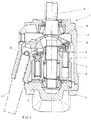
- FIG. 1 shows a greatly simplified section through an axial piston machine according to the disclosure
- FIG. 2 shows a longitudinal section through an adjusting device of the axial piston machine according to FIG. 1 ,
- FIG. 3 shows a second exemplary embodiment of an adjusting device for an axial piston machine according to FIG. 1 .
- FIG. 4 shows a third exemplary embodiment of an adjusting device.
- the axial piston machine is configured as an axial piston pump 1 , the basic construction of which is shown in the section according to FIG. 1 .
- the construction of axial piston pumps 1 of this type is sufficiently well known, for example, from DE 100 01 826 C1 which was cited at the outset, with the result that only the components which are essential to understanding the disclosure will be explained here.
- the axial piston pump 1 has a pump housing 2 , in which a driving mechanism 4 is mounted.
- the latter has a cylinder barrel 6 , in which a multiplicity of axial pistons 8 are guided which in each case delimit a working space 10 .
- the pressure medium supply and pressure medium discharge to and from the working spaces 10 is controlled via control kidneys 12 , 14 which are in pressure medium connection with a pressure connector and a suction connector of the pump.
- the cylinder barrel 6 is driven via a drive shaft 11 which is connected to a motor.
- pivoting angle ⁇ of which can be adjusted in order to change the delivery volume by means of an adjusting device 20 which is indicated using dash-dotted lines.
- the pivot cradle 18 is prestressed via a spring (not shown) into a basic position, in which the pivoting angle and therefore the delivery volume are at their maximum.
- the pivot cradle can be pivoted back counter to the force of said spring and the driving mechanism forces in order to reduce the pivoting angle and therefore the delivery volumetric flow.
- the attachment of the adjusting device 20 to the pivot cradle 18 takes place as shown, for example, via a type of ball and slip joint device 22 .
- FIG. 2 shows an exemplary embodiment of an adjusting device 20 in longitudinal section.
- An adjusting device of this type has substantially a control valve 24 , via which an actuating piston 26 can be adjusted in order to adjust the pivot cradle 18 .
- the adjusting device 20 is configured as power/moment regulator and has a valve bushing 28 which is inserted into a receptacle of the housing 2 .
- the valve bushing 28 has, radially, a pressure connector P, a control connector A and a tank connector T.
- the pressure connector P is in pressure medium connection with the pressure connector of the axial piston pump 1 .
- the tank connector T is in pressure medium connection with a tank or a suction connector of the axial piston pump 1 .
- the control connector A is connected via a housing-side control oil flow path 30 (only shown using dashed lines) to an actuating space 32 which is delimited by the actuating piston 26 and a cylinder or guide bore of the housing 2 .
- the control oil connection to the actuating space 32 can take place, for example, via end-side grooves of the cup-shaped actuating piston 26 ; said grooves are not visible in FIG. 2 .
- the control oil can be guided via bores in the sleeve 34 into the actuating chamber, the bores preferably lying in an axial plane which lies perpendicularly on the sectional plane according to FIG. 2 .
- a sleeve 34 is screwed into the valve bushing 28 , which sleeve 34 is provided with radial bores 36 , 38 , 40 which are firstly in control oil connection with the abovementioned connectors P, A and T and secondly open into a valve bore 42 , in which a control piston 44 of the control valve 24 is guided.
- the valve bore 42 is configured with a radial step 46 , with the result that the control piston 44 is correspondingly also configured as a stepped piston and therefore has a differential face which is provided with the reference numeral 48 in the illustration according to FIG. 2 and is configured on a control collar 50 .
- Two control grooves 52 , 54 are formed on the outer circumference of the control piston 44 , the function of which control grooves 52 , 54 will be explained in yet further detail in the following text.
- the left-hand end section in FIG. 2 of the control piston 44 dips into a spring space 56 which is formed by a radial widened portion of the valve bore 42 .
- That end section of the control piston 44 which lies there is provided with a radial collar 74 , on which a control spring 58 acts.
- the latter is supported on a threaded bolt 60 which is screwed into the sleeve 34 and via which the prestress of the control spring 58 can be set. After adjusting of said prestress, the position of the threaded bolt 60 is fixed via a lock nut 62 .
- a covering 64 then forms the end-side closure, which covering 64 covers the threaded bolt 60 and the lock nut 62 and is placed onto the left-hand end section of the sleeve 34 .
- the sleeve 34 is likewise of displaceable configuration via a thread and two flattened portions which serve as a key face. By way of displacement of the sleeve, the control edges of the control piston are displaced and therefore the point of engagement of the second spring 72 is adapted. The position of the sleeve 34 is fixed by way of the lock nut 78 .
- a stepped spring collar 66 is placed onto said end section, on which spring collar 66 a return spring arrangement 68 is supported with an outer spring 70 and an inner spring 72 which are arranged coaxially with respect to one another and act on a head of the cup-shaped actuating piston 26 .
- Said actuating piston 26 is prestressed in end-side contact against the valve bushing 28 by way of the spring which is mentioned at the outset and prestresses the pivot cradle 18 into the basic position, the grooves for the control oil connection of the actuating space 32 to the control oil flow path 30 running along said end-side bearing region.
- the return spring arrangement the position of the pivot cradle is fed back to the control piston 44 as a force.
- the spring rate and prestress of the spring arrangement 68 are selected to be lower than those of the control spring 58 , with the result that the control piston 44 is prestressed with its radial collar 74 in contact with the end face of the spring space 56 ; this basic position is not shown in FIG. 2 .
- the control groove 52 shuts off the control oil connection between the pressure connector P and the control connector A, whereas the control oil connection between the control connector A and the tank connector T is opened via the further control groove 54 . Accordingly, the actuating space 32 is connected to the tank. However, the pressure at the pressure connector P acts on the differential face 48 . Accordingly, the control piston 44 is loaded in the direction of the basic position (control oil connection between A and T) by the control spring 58 and in the opposed direction (opening of the connection between A and P) by the spring arrangement 68 and the pump pressure which acts on the differential face 48 .
- control piston 44 and also the spring collar 66 are configured with an axial bore 76 , by way of which the two spaces 56 and 68 are connected to one another, with the result that the control piston 44 is loaded on the end side (apart from the differential face 48 , on which the pressure at the connector P acts) with the same pressure, that is to say with the actuating pressure.
- the axial piston pump 1 is first of all pivoted out completely (see FIG. 1 ).
- the pressure at the connector P rises until the pressure which acts on the differential face 48 and the force of the spring arrangement 68 are sufficient to overcome the opposing force which is applied by the control spring 58 , with the result that the control piston 44 is then moved out of its basic position to the left (view in FIG. 2 ) and the pressure medium connection between A and T is closed and correspondingly the pressure medium connection from P to A is opened (see FIG. 2 ).
- the actuating space 32 is then connected to the control oil source, that is to say a line section which conducts the pump pressure, with the result that the actuating piston 26 is moved counter to the force of the spring force which loads the pivot cradle 18 into its basic position and the driving mechanism force and pivots back the pivot cradle 18 .
- the force of the spring arrangement decreases as a result, until a position is reached, in which a force equilibrium again prevails at the control piston 44 .
- the control piston then assumes a control position, in which it covers the radial bore 38 with the control collar 50 .
- control oil is fed to the actuating chamber or discharged from the actuating chamber, in order to maintain the position of the pivot cradle at the prevailing pump pressure. Since the spring arrangement 68 loads both the actuating piston 26 and the control piston 44 , the movement of the pivot cradle 18 is coupled back to the control valve 24 .
- the power regulator operates approximately according to a characteristic curve which is identified by the straight line “ 1 ” in the diagram inserted in FIG. 2 at the bottom left.
- the spring 72 of the springs of the spring arrangement 68 is relieved completely or passes out of active engagement with the actuating piston 26 with a certain residual prestress.
- the force which acts counter to the control spring 58 and is composed of the force of the spring arrangement 68 and the force which results from loading the differential face 48 with pressure is then reduced correspondingly, which results in a steeper course of the characteristic curve, which steeper course is identified by the straight line “ 2 ”.
- the two straight lines “ 1 ” and “ 2 ” therefore result in a resulting characteristic curve which corresponds approximately to the hyperbolic ideal characteristic curve which is shown in the diagram using dash-dotted lines.
- the position of the hyperbola or the straight lines “ 1 ” and “ 2 ” which approximate it can be changed by setting the prestress of the control spring 58 .
- FIG. 3 shows a variant of the exemplary embodiment according to FIG. 2 which differs from the above-described exemplary embodiment only in the way in which the prestress of the control spring 58 is set.
- the construction of the control piston 44 and the spring arrangement 68 and the actuating piston 26 is identical to in the above-described exemplary embodiment, with the result that FIG. 3 shows merely the region which is important for the adjustment of the prestress of the control spring 58 .
- the sleeve 34 is screwed into the valve bushing 28 and is locked via a lock nut 78 .
- the control spring 58 acts on the control piston 44 and is arranged in the spring space 56 , in which the actuating pressure is also active.
- an adapter piece 80 is screwed onto the sleeve 34 in the exemplary embodiment according to FIG. 3 , on which adapter piece 80 a control connector X is formed.
- the threaded bolt 60 is configured with a guide bore 82 which is penetrated by a small piston 84 , on which the control spring 58 is supported.
- a radially widened end section 86 of the small piston 84 is loaded by the control pressure at the control connector X.
- a locking washer 88 which stipulates a basic position of the small piston 84 is arranged at the other end section of the small piston 84 .
- the small piston 84 is displaced to the left out of the illustration according to FIG. 3 by way of the force of the control spring 58 until the locking washer 88 bears against the end face of the threaded bolt 60 ; the control spring 58 is then correspondingly prestressed. If the small piston 84 is loaded with control oil, it is adjusted into its position which is shown in FIG.
- FIG. 4 shows a variant, in which the increase in the prestress does not take place hydraulically, but rather electrically by means of a switching magnet 90 . If a switching magnet were then used instead of the control oil loading in FIG. 3 , said magnet would have to be so powerful that it has to overcome the relatively high prestress of the control spring 58 ; accordingly, a component which was more expensive and also more voluminous would be required.
- FIG. 4 shows a variant, in which the shift of the hyperbola takes place by way of an increase in the prestress of an actuating spring 92 which is arranged coaxially with respect to the control spring 58 and likewise acts on the radially widened collar 74 of the control piston 44 . As in the exemplary embodiment according to FIG.
- the control spring 58 is supported on the threaded bolt 60 which is screwed into the sleeve 34 .
- the prestress of the control spring 58 can therefore be set only by adjusting the threaded bolt 60 .
- the actuating spring 92 is supported on a tappet 94 which for its part can be adjusted via the switching magnet 90 . If the switching magnet 90 is deenergized, the actuating spring 92 is relieved or is loaded only with a comparatively low prestress which is added to that of the control spring 58 . In order to shift the hyperbola, the switching magnet 90 is energized, with the result that the tappet 94 extends and increases the prestress of the actuating spring 92 .
- the required magnetic force for adjustment is very low on account of the low spring rate and prestress of the actuating spring 92 , but is sufficient to shift the hyperbola in the above-described way.
- a proportional magnet can also be used, with the result that a continuous shift of the characteristic curve is made possible.
- the adjusting device according to the disclosure can also of course be used in hydraulic motors or other hydraulic units.
- the axial piston machines can be configured in a swash plate or oblique-axle design.
- the adjusting device has an actuating piston which delimits an actuating space which can be connected to a control oil source or a control oil drain via a control valve.
- a control piston of the control valve is loaded firstly by a control spring and secondly by a spring arrangement which is also in active engagement with the actuating piston.
Landscapes
- Engineering & Computer Science (AREA)
- Mechanical Engineering (AREA)
- General Engineering & Computer Science (AREA)
- Chemical & Material Sciences (AREA)
- Combustion & Propulsion (AREA)
- Reciprocating Pumps (AREA)
- Details Of Reciprocating Pumps (AREA)
Abstract
Description
Claims (20)
Applications Claiming Priority (3)
| Application Number | Priority Date | Filing Date | Title |
|---|---|---|---|
| DE102012022997.6A DE102012022997A1 (en) | 2012-11-24 | 2012-11-24 | Adjustment device for a hydraulic machine and hydraulic axial piston machine |
| DE102012022997 | 2012-11-24 | ||
| DE102012022997.6 | 2012-11-24 |
Publications (2)
| Publication Number | Publication Date |
|---|---|
| US20140147298A1 US20140147298A1 (en) | 2014-05-29 |
| US10570878B2 true US10570878B2 (en) | 2020-02-25 |
Family
ID=50678744
Family Applications (1)
| Application Number | Title | Priority Date | Filing Date |
|---|---|---|---|
| US14/086,904 Active 2037-12-25 US10570878B2 (en) | 2012-11-24 | 2013-11-21 | Adjusting device for a hydraulic machine, and hydraulic axial piston machine |
Country Status (3)
| Country | Link |
|---|---|
| US (1) | US10570878B2 (en) |
| CN (1) | CN103835909B (en) |
| DE (1) | DE102012022997A1 (en) |
Families Citing this family (6)
| Publication number | Priority date | Publication date | Assignee | Title |
|---|---|---|---|---|
| FR3030641B1 (en) * | 2014-12-23 | 2017-01-13 | Poclain Hydraulics Ind | AUTOMATIC CYLINDER SWITCHING DEVICE OF AXIAL PISTON MACHINE |
| JP6688724B2 (en) * | 2016-03-28 | 2020-04-28 | 株式会社神戸製鋼所 | Hydraulic rotary machine |
| CN106438255B (en) * | 2016-10-28 | 2018-08-07 | 浙江大学 | Coaxial homonymy compact variant structural suitable for two-way change displacement plunger pump |
| CH714321A1 (en) * | 2017-11-11 | 2019-05-15 | Liebherr Machines Bulle Sa | Adjusting device for an axial piston machine. |
| DE102018212419A1 (en) * | 2018-07-25 | 2020-01-30 | Danfoss Power Solutions Gmbh & Co. Ohg | TORQUE CONTROL AND RETURN DEVICE |
| DE102018216831A1 (en) * | 2018-10-01 | 2020-04-02 | Robert Bosch Gmbh | Control device for pump pressure and volume flow with concentric control spools |
Citations (6)
| Publication number | Priority date | Publication date | Assignee | Title |
|---|---|---|---|---|
| US4379389A (en) | 1980-09-12 | 1983-04-12 | Caterpillar Tractor Co. | Horsepower consumption control for variable displacement pumps |
| DE4020325A1 (en) | 1990-06-26 | 1992-01-09 | Hydrokraft Gmbh | Swashplate hydraulic pump assembly - has control system which reduces pump flow as delivery pressure increases |
| DE10001826C1 (en) | 2000-01-18 | 2001-09-20 | Brueninghaus Hydromatik Gmbh | Device for regulating the performance of an adjustable piston machine |
| US6684636B2 (en) * | 2001-10-26 | 2004-02-03 | Caterpillar Inc | Electro-hydraulic pump control system |
| US6725658B1 (en) * | 1999-10-12 | 2004-04-27 | Brueninghaus Hydromatik Gmbh | Adjusting device of a swashplate piston engine |
| US7334513B2 (en) * | 2003-12-22 | 2008-02-26 | Brueninghaus Hydromatik Gmbh | Axial piston machine having a fixable slide block on the swash plate |
Family Cites Families (3)
| Publication number | Priority date | Publication date | Assignee | Title |
|---|---|---|---|---|
| AT408898B (en) * | 1998-04-27 | 2002-03-25 | Joerg Thurner | AXIALKOLBENVERSTELLMASCHINE |
| DE102006061145A1 (en) * | 2006-12-22 | 2008-06-26 | Robert Bosch Gmbh | Hydrostatic axial piston machine |
| CN101487458B (en) * | 2008-07-14 | 2012-05-23 | 张全根 | Axial variable displacement plunger pump of swash plate |
-
2012
- 2012-11-24 DE DE102012022997.6A patent/DE102012022997A1/en not_active Withdrawn
-
2013
- 2013-11-21 US US14/086,904 patent/US10570878B2/en active Active
- 2013-11-22 CN CN201310591522.9A patent/CN103835909B/en not_active Expired - Fee Related
Patent Citations (6)
| Publication number | Priority date | Publication date | Assignee | Title |
|---|---|---|---|---|
| US4379389A (en) | 1980-09-12 | 1983-04-12 | Caterpillar Tractor Co. | Horsepower consumption control for variable displacement pumps |
| DE4020325A1 (en) | 1990-06-26 | 1992-01-09 | Hydrokraft Gmbh | Swashplate hydraulic pump assembly - has control system which reduces pump flow as delivery pressure increases |
| US6725658B1 (en) * | 1999-10-12 | 2004-04-27 | Brueninghaus Hydromatik Gmbh | Adjusting device of a swashplate piston engine |
| DE10001826C1 (en) | 2000-01-18 | 2001-09-20 | Brueninghaus Hydromatik Gmbh | Device for regulating the performance of an adjustable piston machine |
| US6684636B2 (en) * | 2001-10-26 | 2004-02-03 | Caterpillar Inc | Electro-hydraulic pump control system |
| US7334513B2 (en) * | 2003-12-22 | 2008-02-26 | Brueninghaus Hydromatik Gmbh | Axial piston machine having a fixable slide block on the swash plate |
Also Published As
| Publication number | Publication date |
|---|---|
| US20140147298A1 (en) | 2014-05-29 |
| DE102012022997A1 (en) | 2014-05-28 |
| CN103835909B (en) | 2018-03-30 |
| CN103835909A (en) | 2014-06-04 |
Similar Documents
| Publication | Publication Date | Title |
|---|---|---|
| US10570878B2 (en) | Adjusting device for a hydraulic machine, and hydraulic axial piston machine | |
| US10954927B2 (en) | Hydraulic pump control system | |
| US10100817B2 (en) | Hydraulic machine of axial-piston design | |
| US11603830B2 (en) | Hydraulic pump with swash plate tilt control | |
| US9541072B2 (en) | Adjustment apparatus for a hydrostatic piston machine, and hydrostatic piston machine having an adjustment apparatus of this kind | |
| CN101595304A (en) | Hydrostatic axial piston engine | |
| US9587652B2 (en) | Hydrostatic drive, in particular hydrostatic fan drive | |
| KR20190042670A (en) | Pulsating pump | |
| US20220082104A1 (en) | Hydraulic fan drive | |
| CN103573573A (en) | Hydrostatic axial piston machine | |
| US10961998B2 (en) | Electro-hydraulic swashplate control arrangement for an axial piston pump | |
| US20140000449A1 (en) | Adjusting device of a hydrostatic module | |
| US10054113B2 (en) | Adjustment device for a hydrostatic piston machine, and hydrostatic axial piston machine | |
| US10408199B2 (en) | Hydrostatic axial piston machine of swash plate design with an adjustable swept volume, in particular hydrostatic axial piston pump | |
| US10054112B2 (en) | Adjustment device for a hydrostatic piston machine, and hydrostatic axial piston machine | |
| CN104948526B (en) | For adjustable hydrostatic pumps, electricity manipulation pressure-regulating valve | |
| CN111794928A (en) | Axial piston machine | |
| US3587394A (en) | High speed control valve for hydraulic drives | |
| US12448955B2 (en) | Displacement control for hydraulic pump | |
| SU761745A1 (en) | Controllable axial-piston hydraulic machine | |
| US20090104047A1 (en) | Pump having multiple minimum flow mechanical stops |
Legal Events
| Date | Code | Title | Description |
|---|---|---|---|
| AS | Assignment |
Owner name: ROBERT BOSCH GMBH, GERMANY Free format text: ASSIGNMENT OF ASSIGNORS INTEREST;ASSIGNORS:DIEBOLD, CAROLA;APPERGER, ANDREAS;REEL/FRAME:032638/0313 Effective date: 20140121 |
|
| STCV | Information on status: appeal procedure |
Free format text: ON APPEAL -- AWAITING DECISION BY THE BOARD OF APPEALS |
|
| STCV | Information on status: appeal procedure |
Free format text: BOARD OF APPEALS DECISION RENDERED |
|
| STPP | Information on status: patent application and granting procedure in general |
Free format text: NOTICE OF ALLOWANCE MAILED -- APPLICATION RECEIVED IN OFFICE OF PUBLICATIONS |
|
| STPP | Information on status: patent application and granting procedure in general |
Free format text: NOTICE OF ALLOWANCE MAILED -- APPLICATION RECEIVED IN OFFICE OF PUBLICATIONS |
|
| STPP | Information on status: patent application and granting procedure in general |
Free format text: PUBLICATIONS -- ISSUE FEE PAYMENT VERIFIED |
|
| STCF | Information on status: patent grant |
Free format text: PATENTED CASE |
|
| MAFP | Maintenance fee payment |
Free format text: PAYMENT OF MAINTENANCE FEE, 4TH YEAR, LARGE ENTITY (ORIGINAL EVENT CODE: M1551); ENTITY STATUS OF PATENT OWNER: LARGE ENTITY Year of fee payment: 4 |