US10570767B2 - Gas turbine engine with a cooling fluid path - Google Patents
Gas turbine engine with a cooling fluid path Download PDFInfo
- Publication number
- US10570767B2 US10570767B2 US15/016,645 US201615016645A US10570767B2 US 10570767 B2 US10570767 B2 US 10570767B2 US 201615016645 A US201615016645 A US 201615016645A US 10570767 B2 US10570767 B2 US 10570767B2
- Authority
- US
- United States
- Prior art keywords
- rotor
- stator
- gas turbine
- turbine engine
- axial face
- Prior art date
- Legal status (The legal status is an assumption and is not a legal conclusion. Google has not performed a legal analysis and makes no representation as to the accuracy of the status listed.)
- Expired - Fee Related, expires
Links
- 239000012809 cooling fluid Substances 0.000 title claims description 10
- 239000012530 fluid Substances 0.000 claims abstract description 17
- 230000000737 periodic effect Effects 0.000 claims description 3
- 238000000034 method Methods 0.000 abstract description 6
- 239000003570 air Substances 0.000 description 35
- 239000007789 gas Substances 0.000 description 22
- 238000001816 cooling Methods 0.000 description 10
- 238000010926 purge Methods 0.000 description 10
- 230000003068 static effect Effects 0.000 description 6
- 238000011144 upstream manufacturing Methods 0.000 description 4
- 239000012080 ambient air Substances 0.000 description 3
- 239000000567 combustion gas Substances 0.000 description 3
- 238000002485 combustion reaction Methods 0.000 description 3
- 230000000979 retarding effect Effects 0.000 description 3
- 238000010586 diagram Methods 0.000 description 2
- 239000000284 extract Substances 0.000 description 2
- 230000037406 food intake Effects 0.000 description 2
- 239000000446 fuel Substances 0.000 description 2
- 238000010438 heat treatment Methods 0.000 description 2
- 238000010248 power generation Methods 0.000 description 2
- 230000009286 beneficial effect Effects 0.000 description 1
- 150000001875 compounds Chemical class 0.000 description 1
- 230000003247 decreasing effect Effects 0.000 description 1
- 230000003993 interaction Effects 0.000 description 1
- 230000033001 locomotion Effects 0.000 description 1
- 230000000149 penetrating effect Effects 0.000 description 1
- 238000007789 sealing Methods 0.000 description 1
Images


Classifications
-
- F—MECHANICAL ENGINEERING; LIGHTING; HEATING; WEAPONS; BLASTING
- F01—MACHINES OR ENGINES IN GENERAL; ENGINE PLANTS IN GENERAL; STEAM ENGINES
- F01D—NON-POSITIVE DISPLACEMENT MACHINES OR ENGINES, e.g. STEAM TURBINES
- F01D5/00—Blades; Blade-carrying members; Heating, heat-insulating, cooling or antivibration means on the blades or the members
- F01D5/02—Blade-carrying members, e.g. rotors
- F01D5/08—Heating, heat-insulating or cooling means
- F01D5/081—Cooling fluid being directed on the side of the rotor disc or at the roots of the blades
-
- F—MECHANICAL ENGINEERING; LIGHTING; HEATING; WEAPONS; BLASTING
- F02—COMBUSTION ENGINES; HOT-GAS OR COMBUSTION-PRODUCT ENGINE PLANTS
- F02C—GAS-TURBINE PLANTS; AIR INTAKES FOR JET-PROPULSION PLANTS; CONTROLLING FUEL SUPPLY IN AIR-BREATHING JET-PROPULSION PLANTS
- F02C7/00—Features, components parts, details or accessories, not provided for in, or of interest apart form groups F02C1/00 - F02C6/00; Air intakes for jet-propulsion plants
- F02C7/12—Cooling of plants
-
- F—MECHANICAL ENGINEERING; LIGHTING; HEATING; WEAPONS; BLASTING
- F01—MACHINES OR ENGINES IN GENERAL; ENGINE PLANTS IN GENERAL; STEAM ENGINES
- F01D—NON-POSITIVE DISPLACEMENT MACHINES OR ENGINES, e.g. STEAM TURBINES
- F01D11/00—Preventing or minimising internal leakage of working-fluid, e.g. between stages
- F01D11/02—Preventing or minimising internal leakage of working-fluid, e.g. between stages by non-contact sealings, e.g. of labyrinth type
-
- F—MECHANICAL ENGINEERING; LIGHTING; HEATING; WEAPONS; BLASTING
- F01—MACHINES OR ENGINES IN GENERAL; ENGINE PLANTS IN GENERAL; STEAM ENGINES
- F01D—NON-POSITIVE DISPLACEMENT MACHINES OR ENGINES, e.g. STEAM TURBINES
- F01D11/00—Preventing or minimising internal leakage of working-fluid, e.g. between stages
- F01D11/001—Preventing or minimising internal leakage of working-fluid, e.g. between stages for sealing space between stator blade and rotor
-
- F—MECHANICAL ENGINEERING; LIGHTING; HEATING; WEAPONS; BLASTING
- F01—MACHINES OR ENGINES IN GENERAL; ENGINE PLANTS IN GENERAL; STEAM ENGINES
- F01D—NON-POSITIVE DISPLACEMENT MACHINES OR ENGINES, e.g. STEAM TURBINES
- F01D11/00—Preventing or minimising internal leakage of working-fluid, e.g. between stages
- F01D11/02—Preventing or minimising internal leakage of working-fluid, e.g. between stages by non-contact sealings, e.g. of labyrinth type
- F01D11/04—Preventing or minimising internal leakage of working-fluid, e.g. between stages by non-contact sealings, e.g. of labyrinth type using sealing fluid, e.g. steam
-
- F—MECHANICAL ENGINEERING; LIGHTING; HEATING; WEAPONS; BLASTING
- F01—MACHINES OR ENGINES IN GENERAL; ENGINE PLANTS IN GENERAL; STEAM ENGINES
- F01D—NON-POSITIVE DISPLACEMENT MACHINES OR ENGINES, e.g. STEAM TURBINES
- F01D5/00—Blades; Blade-carrying members; Heating, heat-insulating, cooling or antivibration means on the blades or the members
- F01D5/02—Blade-carrying members, e.g. rotors
- F01D5/08—Heating, heat-insulating or cooling means
- F01D5/081—Cooling fluid being directed on the side of the rotor disc or at the roots of the blades
- F01D5/082—Cooling fluid being directed on the side of the rotor disc or at the roots of the blades on the side of the rotor disc
-
- F—MECHANICAL ENGINEERING; LIGHTING; HEATING; WEAPONS; BLASTING
- F05—INDEXING SCHEMES RELATING TO ENGINES OR PUMPS IN VARIOUS SUBCLASSES OF CLASSES F01-F04
- F05D—INDEXING SCHEME FOR ASPECTS RELATING TO NON-POSITIVE-DISPLACEMENT MACHINES OR ENGINES, GAS-TURBINES OR JET-PROPULSION PLANTS
- F05D2220/00—Application
- F05D2220/30—Application in turbines
- F05D2220/32—Application in turbines in gas turbines
-
- F—MECHANICAL ENGINEERING; LIGHTING; HEATING; WEAPONS; BLASTING
- F05—INDEXING SCHEMES RELATING TO ENGINES OR PUMPS IN VARIOUS SUBCLASSES OF CLASSES F01-F04
- F05D—INDEXING SCHEME FOR ASPECTS RELATING TO NON-POSITIVE-DISPLACEMENT MACHINES OR ENGINES, GAS-TURBINES OR JET-PROPULSION PLANTS
- F05D2240/00—Components
- F05D2240/10—Stators
-
- F—MECHANICAL ENGINEERING; LIGHTING; HEATING; WEAPONS; BLASTING
- F05—INDEXING SCHEMES RELATING TO ENGINES OR PUMPS IN VARIOUS SUBCLASSES OF CLASSES F01-F04
- F05D—INDEXING SCHEME FOR ASPECTS RELATING TO NON-POSITIVE-DISPLACEMENT MACHINES OR ENGINES, GAS-TURBINES OR JET-PROPULSION PLANTS
- F05D2240/00—Components
- F05D2240/20—Rotors
- F05D2240/24—Rotors for turbines
-
- F—MECHANICAL ENGINEERING; LIGHTING; HEATING; WEAPONS; BLASTING
- F05—INDEXING SCHEMES RELATING TO ENGINES OR PUMPS IN VARIOUS SUBCLASSES OF CLASSES F01-F04
- F05D—INDEXING SCHEME FOR ASPECTS RELATING TO NON-POSITIVE-DISPLACEMENT MACHINES OR ENGINES, GAS-TURBINES OR JET-PROPULSION PLANTS
- F05D2250/00—Geometry
- F05D2250/10—Two-dimensional
- F05D2250/18—Two-dimensional patterned
- F05D2250/184—Two-dimensional patterned sinusoidal
-
- F—MECHANICAL ENGINEERING; LIGHTING; HEATING; WEAPONS; BLASTING
- F05—INDEXING SCHEMES RELATING TO ENGINES OR PUMPS IN VARIOUS SUBCLASSES OF CLASSES F01-F04
- F05D—INDEXING SCHEME FOR ASPECTS RELATING TO NON-POSITIVE-DISPLACEMENT MACHINES OR ENGINES, GAS-TURBINES OR JET-PROPULSION PLANTS
- F05D2260/00—Function
- F05D2260/20—Heat transfer, e.g. cooling
-
- Y—GENERAL TAGGING OF NEW TECHNOLOGICAL DEVELOPMENTS; GENERAL TAGGING OF CROSS-SECTIONAL TECHNOLOGIES SPANNING OVER SEVERAL SECTIONS OF THE IPC; TECHNICAL SUBJECTS COVERED BY FORMER USPC CROSS-REFERENCE ART COLLECTIONS [XRACs] AND DIGESTS
- Y02—TECHNOLOGIES OR APPLICATIONS FOR MITIGATION OR ADAPTATION AGAINST CLIMATE CHANGE
- Y02T—CLIMATE CHANGE MITIGATION TECHNOLOGIES RELATED TO TRANSPORTATION
- Y02T50/00—Aeronautics or air transport
- Y02T50/60—Efficient propulsion technologies, e.g. for aircraft
Definitions
- Turbine engines and particularly gas or combustion turbine engines, are rotary engines that extract energy from a flow of combusted gases passing through the engine onto a multitude of rotating turbine blades.
- Gas turbine engines have been used for land and nautical locomotion and power generation, but are most commonly used for aeronautical applications such as for aircraft, including helicopters. In aircraft, gas turbine engines are used for propulsion of the aircraft. In terrestrial applications, turbine engines are often used for power generation.
- Gas turbine engines for aircraft comprise multiple compressor stages designed with a plurality of bands of blades, generally circumferentially arranged on disks forming the rotor, rotated by a rotor and bands of static vanes disposed between the rotating blades.
- the compressor stages compress the air that is then moved to a combustor and a turbine. Seals are provided between the bands and the rotor, limiting airflow leakage to upstream areas of the compressor, which can reduce efficiency of the system.
- a cooling or purge air flow can be introduced into a rotor to cool the rotor and retard the hot gas path air from entering through openings or gaps in the rotor or between the disks and the static bands.
- embodiments of the invention relate to a gas turbine engine comprising a rotor having at least one disk with a rotor defining an axial face, a stator having at least one ring with a stator axial face confronting the rotor axial face, a recess formed in one of the axial faces to define a buffer cavity, a wing extending into the buffer cavity from the other of the axial faces and having opposing radially inboard and outboard surfaces, a cooling fluid path extending between the rotor and the stator, the fluid path extending through the buffer cavity over the outboard surface of the wing and exiting between terminal portions of the axial faces radially above the outboard surface, and a flow reverser provided within at least one of the outboard surface or the one terminal portion from which the wing extends.
- embodiments of the invention relate to a gas turbine engine comprising a rotor having at least one disk with a rotor defining an axial face, a stator having at least one ring with a stator axial face confronting the rotor axial face, with terminal portions of the axial faces forming an fluid outlet there between, a recess formed in one of the axial faces to define a buffer cavity, a wing extending into the buffer cavity from the other of the axial faces and having a surface confronting the fluid outlet, and a flow reverser provided within at least one of the surface or the terminal portion of the other of the axial faces.
- embodiments of the invention relate to a method of retarding hot air flow in a gas turbine engine from flowing through a cooling air flow path terminating in a fluid outlet between a stator and rotor of the gas turbine engine, the method comprising reversing the hot air flow after entry of the hot air flow into a rim seal cavity.
- FIG. 1 is a schematic cross-sectional diagram of a gas turbine engine for an aircraft.
- FIG. 2 is a section view of a turbine section of the gas turbine engine of FIG. 1 .
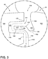
- FIG. 3 is an enlarged view of a section of FIG. 2 illustrating a rotor wing disposed in a channel of an upstream stator.
- FIG. 4 is the same enlarged section of FIG. 3 illustrating a flow path.
- FIG. 5 is a second embodiment of the rotor wing of FIG. 2 .
- FIG. 6 is a third embodiment of the rotor wing of FIG. 2 .
- the described embodiments of the present invention are directed to a cooling fluid path formed between a rotor and stator portion of a turbine section in a gas turbine engine.
- the present invention will be described with respect to the turbine for an aircraft gas turbine engine. It will be understood, however, that the invention is not so limited and may have general applicability within an engine, including compressors, as well as in non-aircraft applications, such as other mobile applications and non-mobile industrial, commercial, and residential applications.
- FIG. 1 is a schematic cross-sectional diagram of a gas turbine engine 10 for an aircraft.
- the engine 10 has a generally longitudinally extending axis or centerline 12 extending forward 14 to aft 16 .
- the engine 10 includes, in downstream serial flow relationship, a fan section 18 including a fan 20 , a compressor section 22 including a booster or low pressure (LP) compressor 24 and a high pressure (HP) compressor 26 , a combustion section 28 including a combustor 30 , a turbine section 32 including a HP turbine 34 , and a LP turbine 36 , and an exhaust section 38 .
- LP booster or low pressure
- HP high pressure
- the fan section 18 includes a fan casing 40 surrounding the fan 20 .
- the fan 20 includes a plurality of fan blades 42 disposed radially about the centerline 12 .
- the HP compressor 26 , the combustor 30 , and the HP turbine 34 form a core 44 of the engine 10 , which generates combustion gases.
- the core 44 is surrounded by core casing 46 , which can be coupled with the fan casing 40 .
- a LP shaft or spool 50 which is disposed coaxially about the centerline 12 of the engine 10 within the larger diameter annular HP spool 48 , drivingly connects the LP turbine 36 to the LP compressor 24 and fan 20 .
- the LP compressor 24 and the HP compressor 26 respectively include a plurality of compressor stages 52 , 54 , in which a set of compressor blades 56 , 58 rotate relative to a corresponding set of static compressor vanes 60 , 62 (also called a nozzle) to compress or pressurize the stream of fluid passing through the stage.
- a single compressor stage 52 , 54 multiple compressor blades 56 , 58 can be provided in a ring and can extend radially outwardly relative to the centerline 12 , from a blade platform to a blade tip, while the corresponding static compressor vanes 60 , 62 are positioned upstream of and adjacent to the rotating blades 56 , 58 . It is noted that the number of blades, vanes, and compressor stages shown in FIG. 1 were selected for illustrative purposes only, and that other numbers are possible.
- the blades 56 , 58 for a stage of the compressor can be mounted to a disk 59 , which is mounted to the corresponding one of the HP and LP spools 48 , 50 , with each stage having its own disk 59 , 61 .
- the vanes 60 , 62 for a stage of the compressor can be mounted to the core casing 46 in a circumferential arrangement.
- the HP turbine 34 and the LP turbine 36 respectively include a plurality of turbine stages 64 , 66 , in which a set of turbine blades 68 , 70 are rotated relative to a corresponding set of static turbine vanes 72 , 74 (also called a nozzle) to extract energy from the stream of fluid passing through the stage.
- multiple turbine vanes 72 , 74 can be provided in a ring and can extend radially outwardly relative to the centerline 12
- the corresponding rotating blades 68 , 70 are positioned downstream of and adjacent to the static turbine vanes 72 , 74 and can also extend radially outwardly relative to the centerline 12 , from a blade platform to a blade tip. It is noted that the number of blades, vanes, and turbine stages shown in FIG. 1 were selected for illustrative purposes only, and that other numbers are possible.
- the blades 68 , 70 for a stage of the turbine can be mounted to a disk 71 , which is mounted to the corresponding one of the HP and LP spools 48 , 50 , with each stage having its own disk 71 , 73 .
- the vanes 72 , 74 for a stage of the compressor can be mounted to the core casing 46 in a circumferential arrangement.
- the portions of the engine 10 mounted to and rotating with either or both of the spools 48 , 50 are also referred to individually or collectively as a rotor 53 .
- the stationary portions of the engine 10 including portions mounted to the core casing 46 are also referred to individually or collectively as a stator 63 .
- the airflow exiting the fan section 18 is split such that a portion of the airflow is channeled into the LP compressor 24 , which then supplies pressurized ambient air 76 to the HP compressor 26 , which further pressurizes the ambient air.
- the pressurized air 76 from the HP compressor 26 is mixed with fuel in the combustor 30 and ignited, thereby generating combustion gases. Some work is extracted from these gases by the HP turbine 34 , which drives the HP compressor 26 .
- the combustion gases are discharged into the LP turbine 36 , which extracts additional work to drive the LP compressor 24 , and the exhaust gas is ultimately discharged from the engine 10 via the exhaust section 38 .
- the driving of the LP turbine 36 drives the LP spool 50 to rotate the fan 20 and the LP compressor 24 .
- a remaining portion of the airflow 78 bypasses the LP compressor 24 and engine core 44 and exits the engine assembly 10 through a stationary vane row, and more particularly an outlet guide vane assembly 80 , comprising a plurality of airfoil guide vanes 82 , at the fan exhaust side 84 . More specifically, a circumferential row of radially extending airfoil guide vanes 82 are utilized adjacent the fan section 18 to exert some directional control of the airflow 78 .
- the ambient air supplied by the fan 20 can bypass the engine core 44 and be used for cooling of portions, especially hot portions, of the engine 10 , and/or used to cool or power other aspects of the aircraft.
- the hot portions of the engine are normally the combustor 30 and components downstream of the combustor 30 , especially the turbine section 32 , with the HP turbine 34 being the hottest portion as it is directly downstream of the combustion section 28 .
- Other sources of cooling fluid can be, but is not limited to, fluid discharged from the LP compressor 24 or the HP compressor 26 . This fluid can be bleed air 77 which can include air drawn from the LP or HP compressors 24 , 26 that bypasses the combustor 30 as cooling sources for the turbine section 32 .
- FIG. 2 depicts a portion of the turbine section 32 including the stator 63 and the rotor 53 , the rotor 53 having at least one disk 71 . While the description herein is written with respect to a turbine, it should be appreciated that the concepts disclosed herein can have equal application to a compressor section.
- Each blade 68 mounts to a blade platform 100 which is further mounted to the disk 71 .
- the blade platform 100 and disk 71 together are part of the rotor 53 defining a rotor axial face 102 .
- the rotor 53 can rotate about the centerline 12 , such that the blades 68 rotate circumferentially around the centerline 12 .
- the stator 63 includes a plurality of vanes 72 , each mounted between a radially inner band 104 and a radially outer band 106 , defining a ring 108 having a stator axial face 110 .
- a radial seal 112 can mount to a stator disk 114 adjacent to the inner band 104 .
- Each vane 72 is circumferentially spaced apart from each other to at least partially define a path for a mainstream airflow M.
- Both the rotor and stator axial faces 102 , 110 are located in an orthogonal plane to the centerline 12 and include interfaces, gaps, and other seals for assembly purposes of the vanes, blades, and associated hardware.
- the mainstream airflow M moves in a forward to aft direction, driving the turbine blades 68 .
- a rim seal cavity 116 is formed between the rotor and stator axial faces 102 , 110 .
- the rim seal cavity 116 can have an ingestion path through which some hot gas airflow from the mainstream airflow M can leak into the rim seal cavity 116 further radially inboard causing unwanted heating of portions of the rotor 53 and stator 63 .
- An exemplary cooling fluid path 118 extends between the confronting axial faces 102 , 110 of the rotor 53 and the stator 63 , through the rim seal cavity 116 which is used to counteract the heating of these portions.
- FIG. 3 an enlarged view of a portion III more clearly details the radial seal 116 which includes a recess 119 formed in one of the axial faces 102 , 110 to define a buffer cavity 120 .
- the recess 119 is formed in the stator axial face 110 and a wing 124 extends from the rotor axial face 102 .
- the wing 124 can extend from the other of the axial faces 110 .
- the wing 124 includes a surface which comprises a radially outboard surface 128 and a radially inboard surface 129 .
- the cooling fluid path 118 terminates in a fluid outlet 121 formed between terminal portions 122 , 123 of the axial faces 102 , 110 radially above the outboard surface 128 .
- a flow reverser 126 comprising a recess 130 , is provided within the outboard surface 128 and the terminal portion 122 from which the wing 124 extends.
- the flow reverser 126 is axial offset from the axial face 102 and adjacent a junction 127 , and can have for example a compound curve or bevel, located between the outboard surface 128 and the terminal portion 122 .
- a purge flow P is fed along the cooling fluid path 118 into a buffer cavity 120 between the stator 63 and adjacent rotor 53 .
- the purge flow P is injected into the buffer cavity 120 to counter hot gas ingestion from the mainstream airflow M into the buffer cavity 120 .
- the purge flow P can also cool the buffer cavity 120 and adjacent components, however interaction between the mainstream flow M and the purge flow can be unsteady, decreasing efficiency of the turbine.
- the purge flow P comprises a cooling air flow C used to counter hot air flow H from the mainstream airflow M into the buffer cavity 120 caused by the relatively higher pressure of the mainstream flow M.
- the wing 124 diverts the cooling fluid path 118 in order to move the cooling air flow C around the wing 124 where it exits at the fluid outlet 121 and meets the hot air flow H.
- the hot air H first flows along the axial face 102 and is turned towards the mainstream flow M by the flow reverser 126 . This turn creates a non-contact seal retarding the hot air H from flowing through the cooling fluid path 118 .
- FIG. 4 also illustrates a method of retarding hot air H in a gas turbine engine 10 from flowing through a cooling air flow path 118 exiting between a stator 63 and rotor 53 of the gas turbine engine 10 .
- the method comprises reversing the hot air flow H after entry of the hot air flow H into the rim seal cavity 116 by turning the hot air flow H with the flow reverser 126 which is fluidly coupled to the cooling air flow path 118 .
- the intersection of the cooling air flow path 118 and the hot air H is an exit point for any purge air P and an entry point for any hot air H, this recessed intersecting region is the fluid outlet 121 for the cooling air flow path 118 .
- the turning occurs downstream of the fluid outlet 121 and upstream of the flow reverser 126 . This turning of the hot air flow H reintroduces flow H to the mainstream flow M.
- any form of circumferential non-uniformity in geometry 132 for example periodic, varied, or sinusoidal, can be formed in the flow reverser 126 .
- the radius from the centerline 12 to the recess 130 would therefore change depending on the circumferential non-uniform geometry 132 .
- the flow reverser 126 need not have the same definition at every circumferential location around the rotor. It may be beneficial that it vary in size, shape, or extent relative to the vanes and/or blades.
- FIG. 5 depicts a second embodiment of a flow reverser 226 having a recess 230 formed in a terminal portion 222 and a recess 231 formed in an outboard surface 228 .
- a junction 227 forms the tip of a smooth arcuate, wavy, or undulating profile formed on an outboard surface 228 and ending on the terminal portion 222 of the axial face 202 .
- FIG. 6 depicts a third embodiment of a flow reverser 326 having a recess 331 formed in an outboard surface 328 with at least one of a smooth arcuate, wavy, or undulating profile.
- the flow reverser 326 is adjacent a junction 327 between the outboard surface 328 and a terminal portion 322 where the terminal portion 322 remains relatively smooth and flat.
- hot air flow H originates from a point radially above the inner band 104 .
- This hot air flow H then runs down the axial face 102 of the rotor 53 into the flow reverser 126 where it is guided such that it is kicked out radially towards the axial face 110 of the stator 63 becoming purge air P.
- Benefits of this flow reverser 126 include holding hot air in the recess 130 and then directing it back to the mainstream flow M.
- the flow reverser 126 placement reduces the mass exchange that normally occurs in the overlapping portions between the stator 63 and rotor 53 which increases durability of the engine 10 while maintaining traditional rotor/stator wings and clearance along the overlapped portions between the stator 63 and rotor 53 .
- This reduction of mass exchange also allows for less purge flow which improves specific fuel consumption (SFC) and better rim sealing which prevents hot air from ingesting past the buffer cavity and damaging portions of the stator and rotor.
- SFC specific fuel consumption
- the geometry of the flow reverser also increases the effectiveness of the rim seal cavity while maintaining blade weight and manufacturability.
Landscapes
- Engineering & Computer Science (AREA)
- Mechanical Engineering (AREA)
- General Engineering & Computer Science (AREA)
- Chemical & Material Sciences (AREA)
- Combustion & Propulsion (AREA)
- Structures Of Non-Positive Displacement Pumps (AREA)
- Turbine Rotor Nozzle Sealing (AREA)
Abstract
Description
Claims (18)
Priority Applications (5)
| Application Number | Priority Date | Filing Date | Title |
|---|---|---|---|
| US15/016,645 US10570767B2 (en) | 2016-02-05 | 2016-02-05 | Gas turbine engine with a cooling fluid path |
| CA2956350A CA2956350A1 (en) | 2016-02-05 | 2017-01-26 | Gas turbine engine with a cooling fluid path |
| JP2017011744A JP2017198187A (en) | 2016-02-05 | 2017-01-26 | Gas turbine engine having cooling fluid passage |
| EP17154134.5A EP3203023A1 (en) | 2016-02-05 | 2017-02-01 | Gas turbine engine with a cooling fluid path |
| CN201710063342.1A CN107061015A (en) | 2016-02-05 | 2017-02-03 | Gas-turbine unit with cooling fluid path |
Applications Claiming Priority (1)
| Application Number | Priority Date | Filing Date | Title |
|---|---|---|---|
| US15/016,645 US10570767B2 (en) | 2016-02-05 | 2016-02-05 | Gas turbine engine with a cooling fluid path |
Publications (2)
| Publication Number | Publication Date |
|---|---|
| US20170226882A1 US20170226882A1 (en) | 2017-08-10 |
| US10570767B2 true US10570767B2 (en) | 2020-02-25 |
Family
ID=57956168
Family Applications (1)
| Application Number | Title | Priority Date | Filing Date |
|---|---|---|---|
| US15/016,645 Expired - Fee Related US10570767B2 (en) | 2016-02-05 | 2016-02-05 | Gas turbine engine with a cooling fluid path |
Country Status (5)
| Country | Link |
|---|---|
| US (1) | US10570767B2 (en) |
| EP (1) | EP3203023A1 (en) |
| JP (1) | JP2017198187A (en) |
| CN (1) | CN107061015A (en) |
| CA (1) | CA2956350A1 (en) |
Cited By (1)
| Publication number | Priority date | Publication date | Assignee | Title |
|---|---|---|---|---|
| US20230010337A1 (en) * | 2021-07-08 | 2023-01-12 | Pratt & Whitney Canada Corp. | Turbine rim seal with lip |
Families Citing this family (2)
| Publication number | Priority date | Publication date | Assignee | Title |
|---|---|---|---|---|
| US10428670B2 (en) | 2016-05-09 | 2019-10-01 | United Technologies Corporation | Ingestion seal |
| IT202000004585A1 (en) | 2020-03-04 | 2021-09-04 | Nuovo Pignone Tecnologie Srl | Improved turbine and blade for root protection from the hot gases of the flow path. |
Citations (18)
| Publication number | Priority date | Publication date | Assignee | Title |
|---|---|---|---|---|
| US3761200A (en) | 1970-12-05 | 1973-09-25 | Secr Defence | Bladed rotors |
| JPS5517207B2 (en) | 1977-10-20 | 1980-05-09 | ||
| US5222742A (en) | 1990-12-22 | 1993-06-29 | Rolls-Royce Plc | Seal arrangement |
| US6506016B1 (en) | 2001-11-15 | 2003-01-14 | General Electric Company | Angel wing seals for blades of a gas turbine and methods for determining angel wing seal profiles |
| US7121791B2 (en) | 2003-04-25 | 2006-10-17 | Rolls-Royce Deutschland Ltd & Co Kg | Main gas duct internal seal of a high-pressure turbine |
| US20070224035A1 (en) | 2005-09-16 | 2007-09-27 | General Electric Company | Angel wing seals for turbine blades and methods for selecting stator, rotor and wing seal profiles |
| EP1939397A2 (en) | 2006-12-19 | 2008-07-02 | General Electric Company | Turbine nozzle with bullnose step-down platform |
| EP1985808A2 (en) | 2007-04-18 | 2008-10-29 | United Technologies Corporation | An abradable sealing for a gas turbine engine and the corresponding method of forming this sealing |
| US7578653B2 (en) | 2006-12-19 | 2009-08-25 | General Electric Company | Ovate band turbine stage |
| US20100008760A1 (en) | 2008-07-10 | 2010-01-14 | Honeywell International Inc. | Gas turbine engine assemblies with recirculated hot gas ingestion |
| US20100074733A1 (en) | 2008-09-25 | 2010-03-25 | Siemens Energy, Inc. | Ingestion Resistant Seal Assembly |
| DE102010017489A1 (en) | 2009-07-02 | 2011-01-05 | General Electric Co. | Turbine machine related systems and devices and seals for turbine engines |
| US8356975B2 (en) * | 2010-03-23 | 2013-01-22 | United Technologies Corporation | Gas turbine engine with non-axisymmetric surface contoured vane platform |
| US20140037435A1 (en) | 2012-08-03 | 2014-02-06 | General Electric Company | Systems and apparatus relating to seals for turbine engines |
| US8707713B2 (en) | 2012-02-15 | 2014-04-29 | United Technologies Corporation | Cooling hole with crenellation features |
| US20140193243A1 (en) | 2013-01-10 | 2014-07-10 | General Electric Company | Seal assembly for turbine system |
| US20140205443A1 (en) * | 2013-01-23 | 2014-07-24 | Siemens Aktiengesellschaft | Seal assembly including grooves in an aft facing side of a platform in a gas turbine engine |
| US9051847B2 (en) | 2012-05-31 | 2015-06-09 | United Technologies Corporation | Floating segmented seal |
Family Cites Families (6)
| Publication number | Priority date | Publication date | Assignee | Title |
|---|---|---|---|---|
| JPH07259505A (en) * | 1994-03-23 | 1995-10-09 | Tohoku Electric Power Co Inc | Turbine blade and manufacturing method thereof |
| JP4764219B2 (en) * | 2006-03-17 | 2011-08-31 | 三菱重工業株式会社 | Gas turbine seal structure |
| US8344874B2 (en) * | 2008-07-10 | 2013-01-01 | Apple Inc. | Intelligent power-enabled communications port |
| JP2010077869A (en) * | 2008-09-25 | 2010-04-08 | Mitsubishi Heavy Ind Ltd | Rim seal structure of gas turbine |
| US20120163955A1 (en) * | 2010-12-23 | 2012-06-28 | General Electric Company | System and method to eliminate a hard rub and optimize a purge flow in a gas turbine |
| EP2886801B1 (en) * | 2013-12-20 | 2019-04-24 | Ansaldo Energia IP UK Limited | Seal system for a gas turbine and corresponding gas turbine |
-
2016
- 2016-02-05 US US15/016,645 patent/US10570767B2/en not_active Expired - Fee Related
-
2017
- 2017-01-26 JP JP2017011744A patent/JP2017198187A/en active Pending
- 2017-01-26 CA CA2956350A patent/CA2956350A1/en not_active Abandoned
- 2017-02-01 EP EP17154134.5A patent/EP3203023A1/en not_active Withdrawn
- 2017-02-03 CN CN201710063342.1A patent/CN107061015A/en active Pending
Patent Citations (20)
| Publication number | Priority date | Publication date | Assignee | Title |
|---|---|---|---|---|
| US3761200A (en) | 1970-12-05 | 1973-09-25 | Secr Defence | Bladed rotors |
| JPS5517207B2 (en) | 1977-10-20 | 1980-05-09 | ||
| US5222742A (en) | 1990-12-22 | 1993-06-29 | Rolls-Royce Plc | Seal arrangement |
| US6506016B1 (en) | 2001-11-15 | 2003-01-14 | General Electric Company | Angel wing seals for blades of a gas turbine and methods for determining angel wing seal profiles |
| US7121791B2 (en) | 2003-04-25 | 2006-10-17 | Rolls-Royce Deutschland Ltd & Co Kg | Main gas duct internal seal of a high-pressure turbine |
| US20070224035A1 (en) | 2005-09-16 | 2007-09-27 | General Electric Company | Angel wing seals for turbine blades and methods for selecting stator, rotor and wing seal profiles |
| EP1939397A2 (en) | 2006-12-19 | 2008-07-02 | General Electric Company | Turbine nozzle with bullnose step-down platform |
| US7578653B2 (en) | 2006-12-19 | 2009-08-25 | General Electric Company | Ovate band turbine stage |
| EP1985808A2 (en) | 2007-04-18 | 2008-10-29 | United Technologies Corporation | An abradable sealing for a gas turbine engine and the corresponding method of forming this sealing |
| US8262342B2 (en) | 2008-07-10 | 2012-09-11 | Honeywell International Inc. | Gas turbine engine assemblies with recirculated hot gas ingestion |
| US20100008760A1 (en) | 2008-07-10 | 2010-01-14 | Honeywell International Inc. | Gas turbine engine assemblies with recirculated hot gas ingestion |
| US20100074733A1 (en) | 2008-09-25 | 2010-03-25 | Siemens Energy, Inc. | Ingestion Resistant Seal Assembly |
| DE102010017489A1 (en) | 2009-07-02 | 2011-01-05 | General Electric Co. | Turbine machine related systems and devices and seals for turbine engines |
| US8317465B2 (en) | 2009-07-02 | 2012-11-27 | General Electric Company | Systems and apparatus relating to turbine engines and seals for turbine engines |
| US8356975B2 (en) * | 2010-03-23 | 2013-01-22 | United Technologies Corporation | Gas turbine engine with non-axisymmetric surface contoured vane platform |
| US8707713B2 (en) | 2012-02-15 | 2014-04-29 | United Technologies Corporation | Cooling hole with crenellation features |
| US9051847B2 (en) | 2012-05-31 | 2015-06-09 | United Technologies Corporation | Floating segmented seal |
| US20140037435A1 (en) | 2012-08-03 | 2014-02-06 | General Electric Company | Systems and apparatus relating to seals for turbine engines |
| US20140193243A1 (en) | 2013-01-10 | 2014-07-10 | General Electric Company | Seal assembly for turbine system |
| US20140205443A1 (en) * | 2013-01-23 | 2014-07-24 | Siemens Aktiengesellschaft | Seal assembly including grooves in an aft facing side of a platform in a gas turbine engine |
Non-Patent Citations (3)
| Title |
|---|
| Chinese Patent Office; Office Action in Chinese Patent Application No. 201710063342.1; dated Aug. 21, 2019; 6 pages; China. |
| Extended European Search Report and Opinion issued in connection with corresponding EP Application No. 17154134.5 dated Jun. 16, 2017. |
| First Office Action and Search issued in connection with corresponding CN Application No. 201710063342.1 dated Mar. 27, 2018. |
Cited By (2)
| Publication number | Priority date | Publication date | Assignee | Title |
|---|---|---|---|---|
| US20230010337A1 (en) * | 2021-07-08 | 2023-01-12 | Pratt & Whitney Canada Corp. | Turbine rim seal with lip |
| US11668203B2 (en) * | 2021-07-08 | 2023-06-06 | Pratt & Whitney Canada Corp. | Turbine rim seal with lip |
Also Published As
| Publication number | Publication date |
|---|---|
| US20170226882A1 (en) | 2017-08-10 |
| JP2017198187A (en) | 2017-11-02 |
| CA2956350A1 (en) | 2017-08-05 |
| EP3203023A1 (en) | 2017-08-09 |
| CN107061015A (en) | 2017-08-18 |
Similar Documents
| Publication | Publication Date | Title |
|---|---|---|
| US10968777B2 (en) | Chordal seal | |
| US11111802B2 (en) | Seal for a gas turbine engine | |
| US10107128B2 (en) | Cooling channels for gas turbine engine component | |
| US20180355753A1 (en) | Spline for a turbine engine | |
| US10443422B2 (en) | Gas turbine engine with a rim seal between the rotor and stator | |
| EP3412871B1 (en) | Sealing arrangement for a turbine vane assembly | |
| US10781709B2 (en) | Turbine engine with a seal | |
| US9803491B2 (en) | Blade outer air seal having shiplap structure | |
| US9863259B2 (en) | Chordal seal | |
| US20180230839A1 (en) | Turbine engine shroud assembly | |
| US10184345B2 (en) | Cover plate assembly for a gas turbine engine | |
| US20180340437A1 (en) | Spline for a turbine engine | |
| US10408075B2 (en) | Turbine engine with a rim seal between the rotor and stator | |
| US20190154050A1 (en) | Rotor hub seal | |
| US20180355754A1 (en) | Spline for a turbine engine | |
| US10598035B2 (en) | Intershaft sealing systems for gas turbine engines and methods for assembling the same | |
| US10240461B2 (en) | Stator rim for a turbine engine | |
| US10570767B2 (en) | Gas turbine engine with a cooling fluid path | |
| US10077666B2 (en) | Method and assembly for reducing secondary heat in a gas turbine engine | |
| EP2995778B1 (en) | Method and assembly for reducing secondary heat in a gas turbine engine | |
| US10443426B2 (en) | Blade outer air seal with integrated air shield | |
| US20160326894A1 (en) | Airfoil cooling passage | |
| US20200049013A1 (en) | Geared gas turbine engine | |
| US20180347403A1 (en) | Turbine engine with undulating profile | |
| US10526897B2 (en) | Cooling passages for gas turbine engine component |
Legal Events
| Date | Code | Title | Description |
|---|---|---|---|
| AS | Assignment |
Owner name: GENERAL ELECTRIC COMPANY, NEW YORK Free format text: ASSIGNMENT OF ASSIGNORS INTEREST;ASSIGNORS:RATZLAFF, JONATHAN RUSSELL;BUNKER, RONALD SCOTT;REEL/FRAME:037673/0864 Effective date: 20160128 |
|
| STPP | Information on status: patent application and granting procedure in general |
Free format text: RESPONSE TO NON-FINAL OFFICE ACTION ENTERED AND FORWARDED TO EXAMINER |
|
| STPP | Information on status: patent application and granting procedure in general |
Free format text: NON FINAL ACTION MAILED |
|
| STPP | Information on status: patent application and granting procedure in general |
Free format text: RESPONSE TO NON-FINAL OFFICE ACTION ENTERED AND FORWARDED TO EXAMINER |
|
| STPP | Information on status: patent application and granting procedure in general |
Free format text: NOTICE OF ALLOWANCE MAILED -- APPLICATION RECEIVED IN OFFICE OF PUBLICATIONS |
|
| ZAAA | Notice of allowance and fees due |
Free format text: ORIGINAL CODE: NOA |
|
| ZAAB | Notice of allowance mailed |
Free format text: ORIGINAL CODE: MN/=. |
|
| STPP | Information on status: patent application and granting procedure in general |
Free format text: PUBLICATIONS -- ISSUE FEE PAYMENT VERIFIED |
|
| STCF | Information on status: patent grant |
Free format text: PATENTED CASE |
|
| FEPP | Fee payment procedure |
Free format text: MAINTENANCE FEE REMINDER MAILED (ORIGINAL EVENT CODE: REM.); ENTITY STATUS OF PATENT OWNER: LARGE ENTITY |
|
| LAPS | Lapse for failure to pay maintenance fees |
Free format text: PATENT EXPIRED FOR FAILURE TO PAY MAINTENANCE FEES (ORIGINAL EVENT CODE: EXP.); ENTITY STATUS OF PATENT OWNER: LARGE ENTITY |
|
| STCH | Information on status: patent discontinuation |
Free format text: PATENT EXPIRED DUE TO NONPAYMENT OF MAINTENANCE FEES UNDER 37 CFR 1.362 |
|
| FP | Lapsed due to failure to pay maintenance fee |
Effective date: 20240225 |