US10569488B2 - Method for setting loop coil embedding depth in conveyor belt, and method for manufacturing conveyor belt - Google Patents
Method for setting loop coil embedding depth in conveyor belt, and method for manufacturing conveyor belt Download PDFInfo
- Publication number
- US10569488B2 US10569488B2 US16/463,343 US201716463343A US10569488B2 US 10569488 B2 US10569488 B2 US 10569488B2 US 201716463343 A US201716463343 A US 201716463343A US 10569488 B2 US10569488 B2 US 10569488B2
- Authority
- US
- United States
- Prior art keywords
- conveyor belt
- loop coils
- embedding depth
- analysis model
- setting
- Prior art date
- Legal status (The legal status is an assumption and is not a legal conclusion. Google has not performed a legal analysis and makes no representation as to the accuracy of the status listed.)
- Expired - Fee Related
Links
Images


Classifications
-
- B—PERFORMING OPERATIONS; TRANSPORTING
- B29—WORKING OF PLASTICS; WORKING OF SUBSTANCES IN A PLASTIC STATE IN GENERAL
- B29D—PRODUCING PARTICULAR ARTICLES FROM PLASTICS OR FROM SUBSTANCES IN A PLASTIC STATE
- B29D29/00—Producing belts or bands
- B29D29/06—Conveyor belts
-
- B—PERFORMING OPERATIONS; TRANSPORTING
- B65—CONVEYING; PACKING; STORING; HANDLING THIN OR FILAMENTARY MATERIAL
- B65G—TRANSPORT OR STORAGE DEVICES, e.g. CONVEYORS FOR LOADING OR TIPPING, SHOP CONVEYOR SYSTEMS OR PNEUMATIC TUBE CONVEYORS
- B65G15/00—Conveyors having endless load-conveying surfaces, i.e. belts and like continuous members, to which tractive effort is transmitted by means other than endless driving elements of similar configuration
- B65G15/30—Belts or like endless load-carriers
- B65G15/32—Belts or like endless load-carriers made of rubber or plastics
- B65G15/34—Belts or like endless load-carriers made of rubber or plastics with reinforcing layers, e.g. of fabric
- B65G15/36—Belts or like endless load-carriers made of rubber or plastics with reinforcing layers, e.g. of fabric the layers incorporating ropes, chains, or rolled steel sections
-
- B—PERFORMING OPERATIONS; TRANSPORTING
- B29—WORKING OF PLASTICS; WORKING OF SUBSTANCES IN A PLASTIC STATE IN GENERAL
- B29K—INDEXING SCHEME ASSOCIATED WITH SUBCLASSES B29B, B29C OR B29D, RELATING TO MOULDING MATERIALS OR TO MATERIALS FOR MOULDS, REINFORCEMENTS, FILLERS OR PREFORMED PARTS, e.g. INSERTS
- B29K2705/00—Use of metals, their alloys or their compounds, for preformed parts, e.g. for inserts
-
- B—PERFORMING OPERATIONS; TRANSPORTING
- B65—CONVEYING; PACKING; STORING; HANDLING THIN OR FILAMENTARY MATERIAL
- B65G—TRANSPORT OR STORAGE DEVICES, e.g. CONVEYORS FOR LOADING OR TIPPING, SHOP CONVEYOR SYSTEMS OR PNEUMATIC TUBE CONVEYORS
- B65G43/00—Control devices, e.g. for safety, warning or fault-correcting
- B65G43/02—Control devices, e.g. for safety, warning or fault-correcting detecting dangerous physical condition of load carriers, e.g. for interrupting the drive in the event of overheating
Definitions
- the present technology relates to a method for setting the embedding depth of loop coils in a conveyor belt which can enhance the durability of a loop coil for detecting vertical tear of a conveyor belt without testing a large number of samples, and a method for manufacturing a conveyor belt in which the loop coil is embedded.
- a conveyor belt in which loop coils are embedded In order to detect vertical tear of a conveyor belt (cracks continuous in the belt longitudinal direction), a conveyor belt in which loop coils are embedded is known (see Japan Unexamined Patent Publication Nos. 2014-31241 and 2015-71493).
- a sensor arranged adjacent to the conveyor belt senses the induced current occurring in loop coils passing near the sensor. If a sharp object or the like to be conveyed pierces the conveyor belt and a vertical tear is generated, the loop coils are damaged, so that no induced current is generated in the loop coils. In this case, the sensor does not detect the induced current even though the loop coils have passed through the vicinity.
- the present technology provides a method for setting the embedding depth of loop coils in a conveyor belt which can enhance the durability of the loop coils for detecting vertical tear of the conveyor belt without testing with numerous samples, and a method for manufacturing a conveyor belt in which the loop coils are embedded.
- a method for setting the embedding depth of loop coils in a conveyor belt is a method for setting the embedding depth of loop coils in a conveyor belt.
- the conveyor belt is provided with a core layer formed by arranging a plurality of metal cords extending in the belt longitudinal direction in parallel with each other in the belt width direction, and an upper cover rubber and a lower cover rubber arranged above and below the core layer, and a plurality of loop coils embedded in the lower cover rubber at intervals in the longitudinal direction of the belt.
- the method comprises the steps of preparing a two-dimensional or three-dimensional FEM analysis model of the conveyor belt, and setting the embedding depth of the loop coils in the conveyor belt on the basis of at least one of a principal stress or a deformation amount occurring in the loop coils in this analysis model when a falling object having predetermined specifications is dropped from above the upper cover rubber in the analysis model to the upper cover rubber.
- a unvulcanized molded body of the conveyor belt in which the loop coils are embedded at an embedding depth position set by the method for setting the embedding depth of loop coils and manufacturing the conveyor belt by vulcanizing the molded body.
- the method for setting the embedding depth of loop coils it is possible by using two-dimensional or three-dimensional FEM (Finite Element Method) analysis model of an actual conveyor belt to reproduce the conditions upon a local impact or an external force acts on the loop coils an actual conveyor belt due to an object to be conveyed being loaded from above the upper cover rubber toward the upper cover rubber.
- FEM Finite Element Method
- FIG. 1 is a cross-sectional view illustrating a conveyor belt manufactured by a manufacturing method according to an embodiment of the present technology.
- FIG. 2 is an explanatory diagram illustrating the internal structure of the conveyor belt of FIG. 1 in a plan view.
- FIG. 3 is an explanatory diagram illustrating a belt conveyor system having the conveyor belt of FIG. 1 installed in a side view.
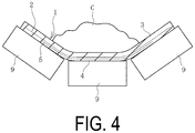
- FIG. 4 is a cross-sectional view taken along A-A of FIG. 3 .
- FIG. 5 is an explanatory diagram illustrating an analysis model of a conveyor belt used for the method for setting the embedding depth of loop coils according to the present technology in a cross-sectional view.
- FIG. 6 is an explanatory diagram schematically illustrating a state in which the analysis model of FIG. 5 receives an impact from the upper cover rubber side.
- FIG. 7 is an explanatory diagram schematically illustrating the analysis model of FIG. 6 in a plan view seen from the upper cover rubber side.
- FIG. 8 is a cross-sectional view illustrating another analysis model.
- FIG. 9 is an explanatory diagram illustrating the internal structure of the analysis model of FIG. 8 in a plan view.
- FIG. 10 is an explanatory diagram schematically illustrating a state in which the analysis model of FIG. 8 receives an impact from the upper cover rubber side in a cross-sectional view.
- FIG. 11 is an explanatory diagram schematically illustrating the analysis model of FIG. 10 in a plan view seen from the upper cover rubber side.
- FIG. 12 is an explanatory diagram illustrating a state in which a molded body is vulcanized in a cross-sectional view.
- a setting method for the embedding depth of loop coils in a conveyor belt (hereinafter, referred to as a setting method) and a manufacturing method for a conveyor belt according to embodiments of the present technology will be described below with reference to the drawings.
- FIGS. 1 and 2 A conveyor belt 1 manufactured by the manufacturing method for a conveyor belt according to the present technology is illustrated in FIGS. 1 and 2 is provided with a core layer 2 , and an upper cover rubber 3 and a lower cover rubber 4 disposed above and below the core layer 2 , which are integrated with one another via vulcanization process.
- the conveyor belt 1 may also include edge rubber disposed on each end portion in the belt width direction or other constituents as appropriate.
- a plurality of metal cords 2 a (steel cords, for example) extending in the belt longitudinal direction are arranged in parallel with each other in the belt width direction.
- the core layer 2 is covered with a cushion rubber, and the cushion rubber is bonded to the upper cover rubber 3 and the lower cover rubber 4 via vulcanization bonding.
- the metal cords 2 a are indicated by dot-dash lines at its center position.
- a rubber composition may be used that contains at least a diene rubber including natural rubber, and carbon black to achieve good wear resistance.
- the layer thicknesses of the upper cover rubber 3 and the lower cover rubber 4 are determined as appropriate according to the performance required of the conveyor belt 1 , within a range of, for example, from 5 mm to 30 mm.
- the cushion rubber is a rubber with excellent adhesion.
- a plurality of loop coils 5 are embedded in the lower cover rubber 4 at intervals in the belt longitudinal direction.
- the loop coils 5 are, for example, a conductive wire 5 a formed in an annular shape, and a known one may be used.
- the conductive wire 5 a may be formed into a wavy shape or a non-wavy shape.
- the loop coils 5 is not limited to a double quadrilateral shape, and various shapes such as a circular shape and an elliptical shape may be adopted.
- the loop coil 5 embedded position in plane is within a region including the central portion in the belt width direction.
- the belt conveyor system 7 illustrated in FIG. 3 is provided with the conveyor belt 1 , a magnetic field generating unit 10 , and a sensor 11 .
- the conveyor belt 1 is stretched between pulleys 8 , 8 , and objects to be conveyed C are loaded to the upper cover rubber 3 through a chute part 13 .
- the conveyor belt 1 is supported on the carrier side in a trough shape projecting downward by support rollers 9 , so that the loaded objects to be conveyed C are placed mainly at the center in the belt width direction.
- the magnetic field generating unit 10 is disposed adjacent to the lower cover rubber 4 .
- the magnetic field generating unit 10 transmits, for example, an electromagnetic wave to each of the loop coils 5 passing near the magnetic field generating unit 10 .
- An induced current is induced in each of the loop coils 5 due to this electromagnetic wave. If the loop coils 5 are disconnected, no induced current is induced.
- the sensor 11 is disposed adjacent to the lower cover rubber 4 .
- the sensor 11 is arranged slightly downstream of the magnetic field generating unit 10 in the forward direction of the conveyor belt 1 .
- the sensor 11 detects whether or not any induced current is generated for each of the loop coils 5 passing near the sensor 11 .
- Detection data from the sensor 11 is transmitted to a control unit 12 .
- the control unit 12 determines that vertical tear has not occurred in the conveyor belt 1 if induced current is generated, and if no induced current is not generated, determines that vertical tear has occurred in the conveyor belt 1 . If it is determined that vertical tear occurs in the conveyor belt 1 , the operation of the conveyor belt 1 is stopped, and a warning or the like is issued.
- an appropriate embedding position is set so that the loop coils 5 are not easily damaged even when such impact or external force acts.
- an appropriate vertical interval (rubber thickness t) between the core layer 2 and loop coils 5 illustrated in FIG. 1 is set. This rubber thickness t is the vertical interval between the lower surface of the core layer 2 and the upper surface of the loop coils 5 .
- a two-dimensional or three-dimensional FEM analysis model 1 A of an actual conveyor belt 1 is used.
- This analysis model 1 A is provided with the same constituent elements as the actual conveyor belt 1 .
- each of the constituent elements of the analysis model 1 A is labeled with the same references as the constituent elements of the actual conveyor belt 1 .
- material property values required for FEM analysis Youngng's modulus, Poisson's ratio, etc. are set for each constituent element, and then input into an arithmetic unit that performs analysis.
- the arithmetic device calculates at least one of the principal stress or the deformation amount, or a change amount corresponding to at least one of the principal stress or the deformation amount, occurring in the loop coils 5 when dropping a falling object W having predetermined specifications from above the upper cover rubber 3 onto the upper cover rubber 3 .
- vertical direction stress and deformation amount occurring in the loop coils 5 are calculated by FEM analysis.
- the specifications and falling height of the falling object W are determined as appropriate on the basis of the usage conditions (shape and weight of object to be conveyed C) of the actual conveyor belt 1 .
- the analysis model 1 A is placed horizontally on a flat rigid body 14 such as a steel sheet.
- the analysis model 1 A may be supported at intervals by support rollers 9 in the belt longitudinal direction as in the actual belt conveyor system 7 , by placing the entire analysis model 1 A on a rigid body 14 , it becomes a severe condition for the loop coils 5 likely to result in damage, so a more appropriate embedding depth position can be set.
- the upper cover rubber 3 and loop coils 5 are locally distorted downward and deform within the area corresponding to the falling point of falling object W, and the metal cords 2 a are displaced in the belt width direction.
- the maximum stress and the maximum deformation amount occurring in the loop coils 5 at this time are calculated. This analysis is performed by varying the embedding depth position of the loop coils 5 (rubber thickness t).
- the relationship between the respective embedding depth positions and the maximum stress or the maximum deformation amount is ascertained, as is the range within which the maximum stress or the maximum deformation amount is minimized, and this range is set as the appropriate embedding depth position of the loop coils 5 in the actual conveyor belt 1 .
- the metal cords 2 a arranged in parallel are joined by cushion rubber interposed in mutual clearance, but the cushion rubber elastically deforms. Therefore, since the force constraining the displacement of the metal cords 2 a in the belt width direction is weak, the metal cords 2 a are locally displaced in the belt width direction, and the interval between the metal cords 2 a in the belt width direction increases.
- the displacement amount of the metal cords 2 a in the belt width direction correlates with the maximum stress and maximum deformation amount occurring in the loop coils 5 .
- an appropriate embedding depth position of the loop coils 5 may be set using the displacement amount of the metal cords 2 a in the belt width direction.
- an appropriate embedding depth at which the durability of the loop coils 5 can be enhanced in the actual conveyor belt 1 can be set without manufacturing and testing a large number of samples. Since it is possible to ascertain the appropriate embedding depth position of the loop coils 5 in the conveyor belt 1 according to its specifications (type of rubber, type of metal cords, etc.) in the development stage of the conveyor belt 1 , it is extremely advantageous.
- the analysis model 1 A may be three-dimensional or two-dimensional, but making the model two-dimensional greatly shortens the time required for model preparation. If the correlation between the displacement amount of the metal cords 2 a in the belt width direction and the maximum stress or the maximum deformation amount occurring in the loop coils 5 can be sufficiently ascertained, then the appropriate embedding depth position of the loop coils 5 can be set with high accuracy with the two-dimensional analysis model 1 A.
- FIG. 8 and FIG. 9 Another analysis model 1 B illustrated in FIG. 8 and FIG. 9 may be used.
- protective layers 6 are embedded in the lower cover rubber 4 at a predetermined vertical depth between the core layer 2 and the loop coils 5 .
- the protective layers 6 are embedded in the lower cover rubber 4 at intervals in the belt longitudinal direction.
- the protective layers 6 have a smaller elongation (higher modulus) than the rubber used for the conveyor belt 1 under the same conditions.
- the protective layers 6 having a thickness of, for example, from 0.2 mm to 3.0 mm is used.
- the protective layers 6 are disposed covering the entire range of the corresponding loop coils 5 (the loop coils 5 disposed nearest to the protective layer 6 ) in a plan view when seen from the upper cover rubber 3 side.
- the metal cords 2 a are indicated by dot-dash lines at its center position, and are omitted in the areas corresponding to the protective layers 6 .
- the lower protective layer 6 is partially cut away.
- the protective layers 6 can be formed of various materials such as natural rubbers, resins, metals and the like.
- Various structures such as a woven structure and a film shape can be adopted for the protective layers 6 .
- As the woven structure a plain weave structure, a cord weave structure, a twill weave structure, a sateen weave structure or the like can be exemplified.
- the protective layers 6 are formed by a plurality of wires 6 a .
- a desired wires 6 a such as natural fibers, resin fibers metal fibers or the like can be used.
- the protective layers 6 have a plain weave structure, and thus a plurality of wires 6 a extending in the belt width direction are disposed in parallel in the belt longitudinal direction.
- the wires 6 a extending in the belt width direction intersect with the metal cords 2 a disposed in parallel in the belt width direction.
- the relationship between the respective embedding depth positions and the maximum stress or the maximum deformation amount is ascertained, as is the range within which the maximum stress or the maximum deformation amount is minimized, and this range is set as the appropriate embedding depth position of the loop coils 5 in the actual conveyor belt 1 .
- a molded body 1 C of an unvulcanized conveyor belt in which the loop coils 5 are embedded at an appropriate embedded depth position set using the above analysis model 1 A is molded. Subsequently, the molded body 1 C is placed in the molds 15 and 15 and vulcanized to manufacture the conveyor belt 1 .
- the loop coils 5 are embedded at an appropriate embedding position set using the above analysis model 1 B, and then a molded body 1 C of an unvulcanized conveyor belt in which a protective layer 6 is embedded in the lower cover rubber 4 at a predetermined vertical depth between the core layer 2 and loop coils 5 is molded. Subsequently, the molded body 1 C is placed in the molds 15 and 15 and vulcanized to manufacture the conveyor belt 1 .
- the loop coils 5 are embedded at an appropriate embedding position set using analysis models 1 A and 1 B.
- analysis models 1 A and 1 B it is easy to prevent damage to loop coils 5 caused by impacts and external forces caused by the objects to be conveyed C loaded to the upper cover rubber 3 . Accordingly, even if vertical tear does not occur on the conveyor belt 1 , it is advantageous for avoiding mistaken recognition that the loop coils 5 are damaged.
- the protective layers 6 are provided on the actual conveyor belt 1 as in the analysis model 1 B, even if a local impact or an external force is act due to the objects to be conveyed C or the like, the displacement of the metal cords 2 a in the belt width direction is suppressed. Thereby, the impact and the external force acting are widely dispersed among the metal cords 2 a . In addition, the impact and the external force are absorbed or lessened by the protective layers 6 . Thus, even if a large impact or an external force acts locally on the conveyor belt 1 , the loop coils 5 are not easily damaged, and its durability is further enhanced. Therefore, it is more advantageous to avoid the situations that the loop coils 5 are damaged even if vertical tear does not occur in the conveyor belt 1 , and it is possible to detect vertical tear in the conveyor belt 1 more accurately.
- the respective loop coils 5 may be disposed together with the respective protective layers 6 in the lower cover rubber 4 in the forming process for the conveyor belt 1 .
- the vertical interval between the core layer 2 and loop coils 5 may be 5 mm or more.
- the appropriate embedding depth position of loop coils 5 calculated using the analysis model 1 B under the same conditions as the analysis model 1 A was approximately the same as the analysis model 1 A.
- a plain weave structure consisting of nylon fibers was used for the protective layers.
- the principal stress and deformation amount occurring in the loop coils 5 were about 60% of that in the analysis model 1 A.
Landscapes
- Engineering & Computer Science (AREA)
- Mechanical Engineering (AREA)
- Belt Conveyors (AREA)
- Control Of Conveyors (AREA)
Abstract
Description
Claims (10)
Applications Claiming Priority (3)
| Application Number | Priority Date | Filing Date | Title |
|---|---|---|---|
| JP2016-228085 | 2016-11-24 | ||
| JP2016228085A JP6819242B2 (en) | 2016-11-24 | 2016-11-24 | How to set the embedding depth of the loop coil on the conveyor belt and how to manufacture the conveyor belt |
| PCT/JP2017/036285 WO2018096800A1 (en) | 2016-11-24 | 2017-10-05 | Method for setting loop coil embedding depth in conveyor belt, and method for manufacturing conveyor belt |
Publications (2)
| Publication Number | Publication Date |
|---|---|
| US20190351633A1 US20190351633A1 (en) | 2019-11-21 |
| US10569488B2 true US10569488B2 (en) | 2020-02-25 |
Family
ID=62195057
Family Applications (1)
| Application Number | Title | Priority Date | Filing Date |
|---|---|---|---|
| US16/463,343 Expired - Fee Related US10569488B2 (en) | 2016-11-24 | 2017-10-05 | Method for setting loop coil embedding depth in conveyor belt, and method for manufacturing conveyor belt |
Country Status (5)
| Country | Link |
|---|---|
| US (1) | US10569488B2 (en) |
| JP (1) | JP6819242B2 (en) |
| CN (1) | CN109996744B (en) |
| DE (1) | DE112017005938B4 (en) |
| WO (1) | WO2018096800A1 (en) |
Cited By (1)
| Publication number | Priority date | Publication date | Assignee | Title |
|---|---|---|---|---|
| US20230159278A1 (en) * | 2020-07-02 | 2023-05-25 | The Yokohama Rubber Co., Ltd. | Device and method for detecting vertical tear in conveyor belt |
Citations (11)
| Publication number | Priority date | Publication date | Assignee | Title |
|---|---|---|---|---|
| JP2002228525A (en) | 2001-01-31 | 2002-08-14 | Bando Chem Ind Ltd | Stress analysis method with input from impact from conveyed object |
| JP2005075617A (en) | 2003-09-03 | 2005-03-24 | Yokohama Rubber Co Ltd:The | Conveyor belt simulation method |
| US20130081929A1 (en) | 2011-09-30 | 2013-04-04 | Veyance Technologies, Inc. | Superelastic low rolling resistance conveyor belt |
| JP2014031241A (en) | 2012-08-02 | 2014-02-20 | Bridgestone Corp | Conveyor belt and conveyor belt device |
| JP2015071493A (en) | 2013-10-04 | 2015-04-16 | 株式会社ブリヂストン | Conveyor belt, and annular conductor for conveyor belt |
| US20150203299A1 (en) * | 2012-07-31 | 2015-07-23 | Bridgestone Corporation | Conveyor belt and conveyor belt apparatus |
| US20150232276A1 (en) * | 2012-08-23 | 2015-08-20 | The Yokohama Rubber Co., Ltd. | Conveyor Belt |
| JP2016185879A (en) | 2015-03-27 | 2016-10-27 | バンドー化学株式会社 | Steel cord conveyor belt longitudinal crack detection device and steel cord conveyor belt longitudinal crack detection system |
| US20180148263A1 (en) * | 2015-06-03 | 2018-05-31 | The Yokohama Rubber Co., Ltd. | Conveyor Belt |
| US20180201449A1 (en) * | 2015-08-24 | 2018-07-19 | The Yokohama Rubber Co., Ltd. | Conveyor Belt Monitoring System |
| US20190128786A1 (en) * | 2016-04-22 | 2019-05-02 | The Yokohama Rubber Co., Ltd. | Impact Test Method and Device |
Family Cites Families (1)
| Publication number | Priority date | Publication date | Assignee | Title |
|---|---|---|---|---|
| DE3347570A1 (en) * | 1983-12-30 | 1985-07-11 | Conrad Scholtz Ag, 2000 Hamburg | Conveyor belt having embedded conductor loops, and method for producing it |
-
2016
- 2016-11-24 JP JP2016228085A patent/JP6819242B2/en active Active
-
2017
- 2017-10-05 WO PCT/JP2017/036285 patent/WO2018096800A1/en not_active Ceased
- 2017-10-05 CN CN201780065587.6A patent/CN109996744B/en active Active
- 2017-10-05 DE DE112017005938.0T patent/DE112017005938B4/en active Active
- 2017-10-05 US US16/463,343 patent/US10569488B2/en not_active Expired - Fee Related
Patent Citations (11)
| Publication number | Priority date | Publication date | Assignee | Title |
|---|---|---|---|---|
| JP2002228525A (en) | 2001-01-31 | 2002-08-14 | Bando Chem Ind Ltd | Stress analysis method with input from impact from conveyed object |
| JP2005075617A (en) | 2003-09-03 | 2005-03-24 | Yokohama Rubber Co Ltd:The | Conveyor belt simulation method |
| US20130081929A1 (en) | 2011-09-30 | 2013-04-04 | Veyance Technologies, Inc. | Superelastic low rolling resistance conveyor belt |
| US20150203299A1 (en) * | 2012-07-31 | 2015-07-23 | Bridgestone Corporation | Conveyor belt and conveyor belt apparatus |
| JP2014031241A (en) | 2012-08-02 | 2014-02-20 | Bridgestone Corp | Conveyor belt and conveyor belt device |
| US20150232276A1 (en) * | 2012-08-23 | 2015-08-20 | The Yokohama Rubber Co., Ltd. | Conveyor Belt |
| JP2015071493A (en) | 2013-10-04 | 2015-04-16 | 株式会社ブリヂストン | Conveyor belt, and annular conductor for conveyor belt |
| JP2016185879A (en) | 2015-03-27 | 2016-10-27 | バンドー化学株式会社 | Steel cord conveyor belt longitudinal crack detection device and steel cord conveyor belt longitudinal crack detection system |
| US20180148263A1 (en) * | 2015-06-03 | 2018-05-31 | The Yokohama Rubber Co., Ltd. | Conveyor Belt |
| US20180201449A1 (en) * | 2015-08-24 | 2018-07-19 | The Yokohama Rubber Co., Ltd. | Conveyor Belt Monitoring System |
| US20190128786A1 (en) * | 2016-04-22 | 2019-05-02 | The Yokohama Rubber Co., Ltd. | Impact Test Method and Device |
Non-Patent Citations (1)
| Title |
|---|
| International Search Report for International Application No. PCT/JP2017/036285 dated Nov. 7, 2017, 4 pages, Japan. |
Cited By (2)
| Publication number | Priority date | Publication date | Assignee | Title |
|---|---|---|---|---|
| US20230159278A1 (en) * | 2020-07-02 | 2023-05-25 | The Yokohama Rubber Co., Ltd. | Device and method for detecting vertical tear in conveyor belt |
| US12043496B2 (en) * | 2020-07-02 | 2024-07-23 | The Yokohama Rubber Co., Ltd. | Device and method for detecting vertical tear in conveyor belt |
Also Published As
| Publication number | Publication date |
|---|---|
| DE112017005938B4 (en) | 2021-05-27 |
| US20190351633A1 (en) | 2019-11-21 |
| CN109996744B (en) | 2020-03-03 |
| DE112017005938T5 (en) | 2019-08-08 |
| CN109996744A (en) | 2019-07-09 |
| JP6819242B2 (en) | 2021-01-27 |
| JP2018083693A (en) | 2018-05-31 |
| WO2018096800A1 (en) | 2018-05-31 |
Similar Documents
| Publication | Publication Date | Title |
|---|---|---|
| US20070279202A1 (en) | Transponder carrier for a tire | |
| AU2012286129B2 (en) | Device for monitoring a conveyor system for the purpose of detecting damage to a conveyor belt by means of sequential conductor loops and a sequential slit protection system | |
| US7752904B2 (en) | Structures with integral life-sensing capability | |
| AU2014265091B2 (en) | Method for monitoring conveyor belt splices | |
| US8439090B2 (en) | Tyre equipped for attaching an object to the wall thereof and fastener therefor | |
| AU2013297827B2 (en) | Conveyor belt and conveyor belt apparatus | |
| US10745207B2 (en) | Conveyor belt and belt conveyor device | |
| EP3225424A1 (en) | Tire | |
| US10569488B2 (en) | Method for setting loop coil embedding depth in conveyor belt, and method for manufacturing conveyor belt | |
| JP2015107878A (en) | Conveyor belt tear detection system with microwire sensor | |
| CN102159919B (en) | Method for measuring and/or inspecting waviness of flat fabrics | |
| JP7440733B2 (en) | Conveyor belt wear monitoring system | |
| CN106241185B (en) | Wear detection type conveyor belt and manufacturing method thereof | |
| CN118219717A (en) | Tire with monitoring device | |
| JP2023101224A (en) | Conveyor belt wear detection device and method | |
| US7954632B2 (en) | Conveyor belt having replaceable segments | |
| US20160001512A1 (en) | Manufacturing method of finite conveyor belt, joining method of finite conveyor belt, manufacturing method of endless conveyor belt, and conveyor belt apparatus | |
| US11378158B2 (en) | Method for producing a belt- or band-shaped component having an electronic device | |
| US11975925B2 (en) | Generation of laminated printed sensor loop stack | |
| JP6822079B2 (en) | Test equipment for evaluation of cut resistance | |
| CN100556678C (en) | Method and apparatus for detecting exposed metal cords in elastic strips | |
| CN105293003A (en) | Longitudinal belt tear detecting method based on machine vision | |
| Kledrowetz et al. | FEM Optimization of a Steel Belt of OTR Tyres | |
| JP2015202931A (en) | rubber belt | |
| KR20110101682A (en) | Passenger detection device of differential car |
Legal Events
| Date | Code | Title | Description |
|---|---|---|---|
| AS | Assignment |
Owner name: THE YOKOHAMA RUBBER CO., LTD., JAPAN Free format text: ASSIGNMENT OF ASSIGNORS INTEREST;ASSIGNOR:HOU, GANG;REEL/FRAME:049260/0819 Effective date: 20190507 |
|
| FEPP | Fee payment procedure |
Free format text: ENTITY STATUS SET TO UNDISCOUNTED (ORIGINAL EVENT CODE: BIG.); ENTITY STATUS OF PATENT OWNER: LARGE ENTITY |
|
| STPP | Information on status: patent application and granting procedure in general |
Free format text: PUBLICATIONS -- ISSUE FEE PAYMENT VERIFIED |
|
| STCF | Information on status: patent grant |
Free format text: PATENTED CASE |
|
| FEPP | Fee payment procedure |
Free format text: MAINTENANCE FEE REMINDER MAILED (ORIGINAL EVENT CODE: REM.); ENTITY STATUS OF PATENT OWNER: LARGE ENTITY |
|
| AS | Assignment |
Owner name: THE YOKOHAMA RUBBER CO., LTD., JAPAN Free format text: CHANGE OF ADDRESS FOR ASSIGNEE;ASSIGNOR:THE YOKOHAMA RUBBER CO., LTD.;REEL/FRAME:065626/0740 Effective date: 20231025 |
|
| LAPS | Lapse for failure to pay maintenance fees |
Free format text: PATENT EXPIRED FOR FAILURE TO PAY MAINTENANCE FEES (ORIGINAL EVENT CODE: EXP.); ENTITY STATUS OF PATENT OWNER: LARGE ENTITY |
|
| STCH | Information on status: patent discontinuation |
Free format text: PATENT EXPIRED DUE TO NONPAYMENT OF MAINTENANCE FEES UNDER 37 CFR 1.362 |
|
| FP | Lapsed due to failure to pay maintenance fee |
Effective date: 20240225 |