US10569202B1 - Transmission filter - Google Patents
Transmission filter Download PDFInfo
- Publication number
- US10569202B1 US10569202B1 US16/265,242 US201916265242A US10569202B1 US 10569202 B1 US10569202 B1 US 10569202B1 US 201916265242 A US201916265242 A US 201916265242A US 10569202 B1 US10569202 B1 US 10569202B1
- Authority
- US
- United States
- Prior art keywords
- opening
- fluid
- bulkhead
- central opening
- baffle
- Prior art date
- Legal status (The legal status is an assumption and is not a legal conclusion. Google has not performed a legal analysis and makes no representation as to the accuracy of the status listed.)
- Active
Links
- 230000005540 biological transmission Effects 0.000 title claims abstract description 51
- 239000012530 fluid Substances 0.000 claims abstract description 71
- 230000004044 response Effects 0.000 claims abstract description 15
- 230000037406 food intake Effects 0.000 claims abstract description 10
- 230000003071 parasitic effect Effects 0.000 description 3
- 230000001174 ascending effect Effects 0.000 description 1
- 230000009194 climbing Effects 0.000 description 1
- 238000002485 combustion reaction Methods 0.000 description 1
- 230000001010 compromised effect Effects 0.000 description 1
- 239000000356 contaminant Substances 0.000 description 1
- 238000010586 diagram Methods 0.000 description 1
- 230000005484 gravity Effects 0.000 description 1
- 230000007246 mechanism Effects 0.000 description 1
- 238000012986 modification Methods 0.000 description 1
- 230000004048 modification Effects 0.000 description 1
- 230000007704 transition Effects 0.000 description 1
Images


Classifications
-
- F—MECHANICAL ENGINEERING; LIGHTING; HEATING; WEAPONS; BLASTING
- F16—ENGINEERING ELEMENTS AND UNITS; GENERAL MEASURES FOR PRODUCING AND MAINTAINING EFFECTIVE FUNCTIONING OF MACHINES OR INSTALLATIONS; THERMAL INSULATION IN GENERAL
- F16H—GEARING
- F16H41/00—Rotary fluid gearing of the hydrokinetic type
- F16H41/24—Details
- F16H41/30—Details relating to venting, lubrication, cooling, circulation of the cooling medium
-
- F—MECHANICAL ENGINEERING; LIGHTING; HEATING; WEAPONS; BLASTING
- F16—ENGINEERING ELEMENTS AND UNITS; GENERAL MEASURES FOR PRODUCING AND MAINTAINING EFFECTIVE FUNCTIONING OF MACHINES OR INSTALLATIONS; THERMAL INSULATION IN GENERAL
- F16H—GEARING
- F16H57/00—General details of gearing
- F16H57/04—Features relating to lubrication or cooling or heating
- F16H57/0402—Cleaning of lubricants, e.g. filters or magnets
- F16H57/0404—Lubricant filters
-
- B—PERFORMING OPERATIONS; TRANSPORTING
- B01—PHYSICAL OR CHEMICAL PROCESSES OR APPARATUS IN GENERAL
- B01D—SEPARATION
- B01D35/00—Filtering devices having features not specifically covered by groups B01D24/00 - B01D33/00, or for applications not specifically covered by groups B01D24/00 - B01D33/00; Auxiliary devices for filtration; Filter housing constructions
- B01D35/005—Filters specially adapted for use in internal-combustion engine lubrication or fuel systems
-
- B—PERFORMING OPERATIONS; TRANSPORTING
- B01—PHYSICAL OR CHEMICAL PROCESSES OR APPARATUS IN GENERAL
- B01D—SEPARATION
- B01D35/00—Filtering devices having features not specifically covered by groups B01D24/00 - B01D33/00, or for applications not specifically covered by groups B01D24/00 - B01D33/00; Auxiliary devices for filtration; Filter housing constructions
- B01D35/02—Filters adapted for location in special places, e.g. pipe-lines, pumps, stop-cocks
- B01D35/027—Filters adapted for location in special places, e.g. pipe-lines, pumps, stop-cocks rigidly mounted in or on tanks or reservoirs
- B01D35/0273—Filtering elements with a horizontal or inclined rotation or symmetry axis submerged in tanks or reservoirs
-
- B—PERFORMING OPERATIONS; TRANSPORTING
- B01—PHYSICAL OR CHEMICAL PROCESSES OR APPARATUS IN GENERAL
- B01D—SEPARATION
- B01D35/00—Filtering devices having features not specifically covered by groups B01D24/00 - B01D33/00, or for applications not specifically covered by groups B01D24/00 - B01D33/00; Auxiliary devices for filtration; Filter housing constructions
- B01D35/14—Safety devices specially adapted for filtration; Devices for indicating clogging
- B01D35/153—Anti-leakage or anti-return valves
-
- B—PERFORMING OPERATIONS; TRANSPORTING
- B01—PHYSICAL OR CHEMICAL PROCESSES OR APPARATUS IN GENERAL
- B01D—SEPARATION
- B01D35/00—Filtering devices having features not specifically covered by groups B01D24/00 - B01D33/00, or for applications not specifically covered by groups B01D24/00 - B01D33/00; Auxiliary devices for filtration; Filter housing constructions
- B01D35/14—Safety devices specially adapted for filtration; Devices for indicating clogging
- B01D35/157—Flow control valves: Damping or calibrated passages
- B01D35/1573—Flow control valves
-
- F—MECHANICAL ENGINEERING; LIGHTING; HEATING; WEAPONS; BLASTING
- F16—ENGINEERING ELEMENTS AND UNITS; GENERAL MEASURES FOR PRODUCING AND MAINTAINING EFFECTIVE FUNCTIONING OF MACHINES OR INSTALLATIONS; THERMAL INSULATION IN GENERAL
- F16H—GEARING
- F16H57/00—General details of gearing
- F16H57/04—Features relating to lubrication or cooling or heating
- F16H57/0434—Features relating to lubrication or cooling or heating relating to lubrication supply, e.g. pumps; Pressure control
- F16H57/0435—Pressure control for supplying lubricant; Circuits or valves therefor
-
- F—MECHANICAL ENGINEERING; LIGHTING; HEATING; WEAPONS; BLASTING
- F16—ENGINEERING ELEMENTS AND UNITS; GENERAL MEASURES FOR PRODUCING AND MAINTAINING EFFECTIVE FUNCTIONING OF MACHINES OR INSTALLATIONS; THERMAL INSULATION IN GENERAL
- F16H—GEARING
- F16H57/00—General details of gearing
- F16H57/04—Features relating to lubrication or cooling or heating
- F16H57/0434—Features relating to lubrication or cooling or heating relating to lubrication supply, e.g. pumps; Pressure control
- F16H57/0443—Features relating to lubrication or cooling or heating relating to lubrication supply, e.g. pumps; Pressure control for supply of lubricant during tilt or high acceleration, e.g. problems related to the tilt or extreme acceleration of the transmission casing and the supply of lubricant under these conditions
Definitions
- This disclosure relates to the field of transmission systems. More particularly, the disclosure pertains to a transmission filter designed to prevent air ingestion when a vehicle is accelerating, decelerating, or on a grade.
- Automatic transmission fluid serves many functions in a modem automatic transmission.
- Pressurized fluid may be used to engage friction clutches in order to establish a power flow path with a desired speed ratio.
- Fluid lubricates gears and bearings. Excess heat is removed by fluid flowing over various components. When the fluid contains contaminants, it may be less effective in these functions and may cause failures such as stuck valves. Therefore, transmissions often include fluid filters.
- the fluid typically drains to a sump due to gravity.
- a transmission pump draws fluid from the sump and delivers pressurized fluid to a valve body, which distributes the fluid to various places within the transmission at pressures appropriate to the various functions.
- a transmission includes a filter housing, a baffle, and a valve.
- the filter housing contains filter media and defines an inlet.
- the baffle defines front and rear openings.
- the baffle may be fixed to the filter housing.
- the valve is located within the baffle.
- the baffle may include a front bulkhead between the front opening and the inlet and a rear bulkhead between the rear opening and the inlet.
- the valve is configured to prevent air ingestion into the inlet. Specifically, the valve prevents flow from the front opening to the inlet in response to weight of fluid on a front side of the valve when the front opening is elevated relative to the rear opening.
- the valve also prevents flow from the rear opening to the inlet in response to weight of fluid on a rear side of the valve when the rear opening is elevated relative to the front opening.
- the valve may include a front plate and rear plate.
- the front plate may be located between the front opening and the front bulkhead.
- the rear plate may be located between the rear opening and the rear bulkhead.
- the front and rear plates may be supported to slide in unison in response to the weight of fluid on a higher side of the valve between a first position in which the front plate prevents flow through the front bulkhead and a second position in which the rear plate prevents flow through the rear bulkhead.
- the transmission may further include a gearbox, a valve body, and a pump.
- a transmission filter includes a filter housing, a baffle, and a valve.
- the filter housing contains filter media and defines a central opening.
- the baffle is fixed to the filter housing around the central opening.
- the baffle defines front and rear openings.
- the baffle may include a front bulkhead between the front opening and the central opening and a rear bulkhead between the rear opening and the central opening.
- the valve located within the baffle, is configured to alternately prevent flow from the front opening to the central opening and from the rear opening to the central opening in response to weight of fluid on a higher side of the valve.
- the valve may include front and rear plates.
- the front plate may be located between the front opening and the front bulkhead.
- the rear plate may be located between the rear opening and the rear bulkhead.
- the front and rear plates may be supported to slide in unison in response to the weight of fluid on the higher side of the valve between a first position in which the front plate prevents flow through the front bulkhead and a second position in which the rear plate prevents flow through the rear bulkhead.
- a transmission filter includes a filter housing, a baffle, and a rear plate.
- the filter housing contains filter media and defines a central opening.
- the baffle is fixed to the filter housing around the central opening.
- the baffle defines front and rear openings and has a rear bulkhead between the rear opening and the central opening to permit fluid flow from the rear opening to the central opening.
- the rear plate is supported to slide toward the central opening when the rear opening is higher than the front opening in response to weight of fluid between the rear plate and the rear opening. In this position, the rear plate seals against the rear bulkhead to prevent flow from the rear opening to the central opening.
- the baffle may also include a front bulkhead located between the front opening and the central opening to permit fluid flow from the front opening to the central opening.
- a front plate may be supported to slide toward the central opening when the front opening is higher than the rear opening in response to weight of fluid between the front plate and the front opening. In this position, the front plate seals against the front bulkhead to prevent flow from the front opening to the central opening.
- the front plate and the rear plate may be linked to slide in unison such that flow is permitted from the rear opening to the central opening whenever flow is prevented from the front opening to the central opening and such that flow is permitted from the front opening to the central opening whenever flow is prevented from the rear opening to the central opening.
- FIG. 1 is a schematic diagram of a transmission hydraulic system.
- FIG. 2 is a cross sectional view of a first transmission filter system when a vehicle is on level ground at constant speed.
- FIG. 3 is a cross sectional view of the first transmission filter system of FIG. 2 when the vehicle is decelerating or descending a grade.
- FIG. 4 is a cross sectional view of a second transmission filter system when a vehicle is on level ground at constant speed.
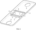
- FIG. 5 is a pictorial view of a baffle and slider mechanism of the second transmission filter system of FIG. 4 .
- FIG. 6 is a cross sectional view of the second transmission filter system of FIG. 4 when the vehicle is decelerating or descending a grade.
- FIG. 7 is a cross sectional view of the second transmission filter system of FIG. 4 when the vehicle is accelerating or ascending a grade.
- FIG. 8 is a pictorial view of a third transmission filter system.
- FIG. 1 schematically illustrates a transmission hydraulic system.
- Bold lines indicate mechanical power flow.
- Thin solid lines indicate flow of hydraulic fluid.
- Transmission input shaft 10 is connected to a power source such as a crankshaft of an internal combustion engine. Power is delivered to torque converter 12 which drives turbine shaft 14 . Clutches within gearbox 16 are engaged to establish a power flow path from turbine shaft 14 to output shaft 18 . Different power flow paths having different speed ratios may be established by engaging different clutches.
- output shaft 18 is connected to a driveshaft which transmits the power to a rear differential and then to rear wheels.
- a transfer case may be installed between the output shaft and the driveshaft to divert a portion of the power to a front differential and then to front wheels.
- the output shaft may transmit power to a front differential via gears or a chain.
- Mechanical pump 20 draws fluid from sump 22 , through filter 24 , and delivers the fluid, at increased pressure, to valve body 26 .
- the pressure at which fluid enters the valve body may be called line pressure.
- a network of control valves within the valve body deliver fluid to the torque converter and to gearbox components at desired pressures less than line pressure and at desired flow rates. Fluid drains from the control valves and from the gearbox back into sump 22 .
- FIG. 2 is a cross section of a portion of a transmission assembly including pump 20 , sump 22 , and a first type of filter 24 .
- Sump 22 is formed by joining together a front case half 30 and a rear case half 32 .
- Pump 20 is supported by front case half 30 .
- Filter 24 includes a single inlet 34 located near the center of the sum, an outlet tube 36 , and filter media 38 .
- Filter outlet tube 36 is sealed to pump inlet tube 40 by a seal 42 . Fluid flows from the sump 22 , through filter inlet port 34 , through filter media 38 , through filter outlet tube 36 , through pump inlet tube 40 , into pump 20 .
- the height of the surface 44 of transmission fluid in the sump is determined by the quantity of fluid.
- the quantity must be sufficient to keep the inlet in fluid even when a substantial amount of fluid is either in the transmission components or draining back to the sump along the walls of the transmission case. When the fluid is cold, it can take a long time for fluid to drain back into the sump.
- FIG. 3 shows the filter of FIG. 2 when the vehicle is descending a hill.
- the fluid level becomes much deeper at the front of the sump and shallower in the vicinity of inlet 34 . This can also happen when the vehicle decelerates rapidly on level terrain.
- the inlet 34 is above the fluid surface 44 , as shown in FIG. 3 , then air is drawn into the filter instead of transmission fluid. Short periods of air ingestion may cause noise and/or unstable line pressure. Long periods of air ingestion would result in loss of ability to transmit power and potential damage to transmission components.
- the quantity of fluid in the transmission may be increased. However, if the fluid surface 44 is too high, rotating transmission components may splash into the fluid causing parasitic drag. It may be impossible to find a fluid quantity that avoids air ingestion in the worst case low level condition and also avoids high parasitic losses in other conditions.
- FIG. 4 illustrates a second type of transmission filter designed to avoid the air ingestion issue.
- Filter 24 ′ includes a housing filled with filter media 38 .
- the housing may be formed by a top piece 50 and a bottom piece 52 that are fused together after installing the filter media.
- the bottom piece 52 defines an inlet opening 54 to admit transmission fluid to the housing.
- the inlet opening is centrally located within the filter housing and may be called a central opening.
- a baffle 56 is fixed to the bottom piece 52 .
- the baffle defines a front opening 58 and a rear opening 60 .
- a valve assembly 62 is located within the channel formed by the baffle 56 and the bottom piece 52 .
- the valve A assembly selectively seals off the channel between the front opening 58 and the inlet opening 54 or between the rear opening 60 and the inlet opening.
- the valve may have a central position, as shown in FIG. 4 , in which fluid may flow from both the front opening and the rear opening to the inlet opening.
- FIG. 5 illustrates the structure of valve 62 .
- a slider includes a front plate 64 and a rear plate 66 connected by rails 68 and 70 .
- the baffle includes two bulkheads 72 and 74 .
- a top edge of front bulkhead 72 seals against the bottom of bottom piece 52 between the front opening 58 and the central opening 54 . Fluid flowing from front opening 58 to central opening 54 must pass through an opening in bulkhead 72 .
- a top edge of rear bulkhead 74 seals against the bottom of bottom piece 52 between the rear opening 60 and the central opening 54 . Fluid flowing from rear opening 60 to central opening 54 must pass through an opening in bulkhead 74 .
- the rails 68 and 70 pass through the openings of the bulkheads.
- FIG. 6 shows the transmission of FIG. 4 when the vehicle is on a downhill slope. The same phenomena occur when the vehicle is decelerating on level ground. Note that the fluid in sump 22 has moved to the front of the sump. Although front opening 58 is still submerged, rear opening 60 is above the surface 46 . A quantity of transmission fluid 80 is trapped by baffle 56 behind the rear bulkhead 74 . The weight of the fluid 80 causes valve 62 to close the opening in the rear bulkhead. Therefore, air is not ingested into the filter media and valve body. Fluid is drawn through the front opening 58 , through the opening in the front bulkhead 72 , through the filter media 38 and into the valve body.
- FIG. 7 shows the transmission of FIG. 4 when the vehicle is on an uphill slope.
- the fluid in sump 22 has moved to the back of the sump.
- Front opening 58 is now above the surface 46 while rear opening 60 is submerged.
- a quantity of transmission fluid 82 is trapped by baffle 56 in front of the front bulkhead 72 .
- the weight of the fluid 82 causes valve 62 to close the opening in the front bulkhead. Therefore, air is not ingested into the filter media and valve body. Fluid is drawn through the rear opening 60 , through the opening in the rear bulkhead 74 , through the filter media 38 and into the valve body.
- the minimum fluid level can be lower while still preventing air ingestion when the vehicle is accelerating or decelerating or climbing or descending a grade.
- the average and maximum fluid levels are directly related to the minimum fluid level. Therefore, the frequency of the fluid level being high enough that rotating parts contact the surface, causing parasitic drag, is reduced.
- FIG. 8 illustrates an alternate embodiment of the filter assembly.
- baffle 56 ′ is tapered such that it is narrower at the ends than adjacent to the inlet.
- Front and rear openings 58 ′ and 60 ′ are each defined partially by an edge of the baffle and partially by a bottom of filter housing 50 .
- the front and rear openings face axially as opposed to facing downward.
- the inventors have found that this embodiment can be positioned closer to the bottom of the transmission sump than the embodiment of FIG. 4-7 .
- this embodiment is less likely to trap air in one end of the baffle as that end transitions from being high to being low.
Landscapes
- Engineering & Computer Science (AREA)
- General Engineering & Computer Science (AREA)
- Mechanical Engineering (AREA)
- Chemical & Material Sciences (AREA)
- Chemical Kinetics & Catalysis (AREA)
- Combustion & Propulsion (AREA)
- General Details Of Gearings (AREA)
Abstract
A transmission filter includes a baffle with a valve. The baffle defines front and rear openings. When a vehicle climbs or descends a hill, the valve moves in response to the weight of fluid on a higher side of the baffle. The valve prevents flow from the higher of the front and rear openings preventing air ingestion into the filter.
Description
This disclosure relates to the field of transmission systems. More particularly, the disclosure pertains to a transmission filter designed to prevent air ingestion when a vehicle is accelerating, decelerating, or on a grade.
Automatic transmission fluid serves many functions in a modem automatic transmission. Pressurized fluid may be used to engage friction clutches in order to establish a power flow path with a desired speed ratio. Fluid lubricates gears and bearings. Excess heat is removed by fluid flowing over various components. When the fluid contains contaminants, it may be less effective in these functions and may cause failures such as stuck valves. Therefore, transmissions often include fluid filters. The fluid typically drains to a sump due to gravity. A transmission pump draws fluid from the sump and delivers pressurized fluid to a valve body, which distributes the fluid to various places within the transmission at pressures appropriate to the various functions.
A transmission includes a filter housing, a baffle, and a valve. The filter housing contains filter media and defines an inlet. The baffle defines front and rear openings. The baffle may be fixed to the filter housing. The valve is located within the baffle. The baffle may include a front bulkhead between the front opening and the inlet and a rear bulkhead between the rear opening and the inlet. The valve is configured to prevent air ingestion into the inlet. Specifically, the valve prevents flow from the front opening to the inlet in response to weight of fluid on a front side of the valve when the front opening is elevated relative to the rear opening. The valve also prevents flow from the rear opening to the inlet in response to weight of fluid on a rear side of the valve when the rear opening is elevated relative to the front opening. The valve may include a front plate and rear plate. The front plate may be located between the front opening and the front bulkhead. The rear plate may be located between the rear opening and the rear bulkhead. The front and rear plates may be supported to slide in unison in response to the weight of fluid on a higher side of the valve between a first position in which the front plate prevents flow through the front bulkhead and a second position in which the rear plate prevents flow through the rear bulkhead. The transmission may further include a gearbox, a valve body, and a pump.
A transmission filter includes a filter housing, a baffle, and a valve. The filter housing contains filter media and defines a central opening. The baffle is fixed to the filter housing around the central opening. The baffle defines front and rear openings. The baffle may include a front bulkhead between the front opening and the central opening and a rear bulkhead between the rear opening and the central opening. The valve, located within the baffle, is configured to alternately prevent flow from the front opening to the central opening and from the rear opening to the central opening in response to weight of fluid on a higher side of the valve. The valve may include front and rear plates. The front plate may be located between the front opening and the front bulkhead. The rear plate may be located between the rear opening and the rear bulkhead. The front and rear plates may be supported to slide in unison in response to the weight of fluid on the higher side of the valve between a first position in which the front plate prevents flow through the front bulkhead and a second position in which the rear plate prevents flow through the rear bulkhead.
A transmission filter includes a filter housing, a baffle, and a rear plate. The filter housing contains filter media and defines a central opening. The baffle is fixed to the filter housing around the central opening. The baffle defines front and rear openings and has a rear bulkhead between the rear opening and the central opening to permit fluid flow from the rear opening to the central opening. The rear plate is supported to slide toward the central opening when the rear opening is higher than the front opening in response to weight of fluid between the rear plate and the rear opening. In this position, the rear plate seals against the rear bulkhead to prevent flow from the rear opening to the central opening. The baffle may also include a front bulkhead located between the front opening and the central opening to permit fluid flow from the front opening to the central opening. A front plate may be supported to slide toward the central opening when the front opening is higher than the rear opening in response to weight of fluid between the front plate and the front opening. In this position, the front plate seals against the front bulkhead to prevent flow from the front opening to the central opening. The front plate and the rear plate may be linked to slide in unison such that flow is permitted from the rear opening to the central opening whenever flow is prevented from the front opening to the central opening and such that flow is permitted from the front opening to the central opening whenever flow is prevented from the rear opening to the central opening.
Embodiments of the present disclosure are described herein. It is to be understood, however, that the disclosed embodiments are merely examples and other embodiments can take various and alternative forms. The figures are not necessarily to scale; some features could be exaggerated or minimized to show details of particular components. Therefore, specific structural and functional details disclosed herein are not to be interpreted as limiting, but merely as a representative basis for teaching one skilled in the art to variously employ the present invention. As those of ordinary skill in the art will understand, various features illustrated and described with reference to any one of the figures can be combined with features illustrated in one or more other figures to produce embodiments that are not explicitly illustrated or described. The combinations of features illustrated provide representative embodiments for typical applications. Various combinations and modifications of the features consistent with the teachings of this disclosure, however, could be desired for particular applications or implementations.
Some engine power is diverted to drive mechanical pump 20. Mechanical pump 20 draws fluid from sump 22, through filter 24, and delivers the fluid, at increased pressure, to valve body 26. The pressure at which fluid enters the valve body may be called line pressure. A network of control valves within the valve body deliver fluid to the torque converter and to gearbox components at desired pressures less than line pressure and at desired flow rates. Fluid drains from the control valves and from the gearbox back into sump 22.
When the rear opening is higher than the front opening, the weight of fluid between the rear opening 60 and the rear plate 66 cause the slider to move to the position shown in FIG. 5 . In this position, rear plate 66 seals the opening in rear bulkhead 74, preventing the flow of fluid or air from the rear opening 60 to the central opening 54. Thus, in this condition the filter draws fluid exclusively from the lower front opening.
Similarly, FIG. 7 shows the transmission of FIG. 4 when the vehicle is on an uphill slope. The same phenomena occur when the vehicle is accelerating on level ground. The fluid in sump 22 has moved to the back of the sump. Front opening 58 is now above the surface 46 while rear opening 60 is submerged. A quantity of transmission fluid 82 is trapped by baffle 56 in front of the front bulkhead 72. The weight of the fluid 82 causes valve 62 to close the opening in the front bulkhead. Therefore, air is not ingested into the filter media and valve body. Fluid is drawn through the rear opening 60, through the opening in the rear bulkhead 74, through the filter media 38 and into the valve body.
With the filter design of FIGS. 4-7 , the minimum fluid level can be lower while still preventing air ingestion when the vehicle is accelerating or decelerating or climbing or descending a grade. The average and maximum fluid levels are directly related to the minimum fluid level. Therefore, the frequency of the fluid level being high enough that rotating parts contact the surface, causing parasitic drag, is reduced.
While exemplary embodiments are described above, it is not intended that these embodiments describe all possible forms encompassed by the claims. The words used in the specification are words of description rather than limitation, and it is understood that various changes can be made without departing from the spirit and scope of the disclosure. As previously described, the features of various embodiments can be combined to form further embodiments of the invention that may not be explicitly described or illustrated. While various embodiments could have been described as providing advantages or being preferred over other embodiments or prior art implementations with respect to one or more desired characteristics, those of ordinary skill in the art recognize that one or more features or characteristics can be compromised to achieve desired overall system attributes, which depend on the specific application and implementation. As such, embodiments described as less desirable than other embodiments or prior art implementations with respect to one or more characteristics are not outside the scope of the disclosure and can be desirable for particular applications.
Claims (12)
1. A transmission comprising:
a filter housing containing filter media and defining an inlet;
a baffle defining front and rear openings; and
a valve within the baffle configured to prevent flow from the front opening to the inlet in response to weight of fluid on a front side of the valve when the front opening is elevated relative to the rear opening and to prevent flow from the rear opening to the inlet in response to weight of fluid on a rear side of the valve when the rear opening is elevated relative to the front opening to prevent air ingestion into the inlet.
2. The transmission of claim 1 further comprising:
a gearbox;
a valve body configured to distribute fluid to the gearbox; and
a pump configured to draw fluid from a sump, through the filter media, and supply the fluid to the valve body.
3. The transmission of claim 1 wherein the baffle is fixed to the filter housing.
4. The transmission of claim 3 wherein the baffle comprises a front bulkhead between the front opening and the inlet and a rear bulkhead between the rear opening and the inlet.
5. The transmission of claim 4 wherein the valve comprises:
a front plate between the front opening and the front bulkhead; and
a rear plate between the rear opening and the rear bulkhead wherein the front and rear plates are supported to slide in unison in response to the weight of fluid on a higher side of the valve between a first position in which the front plate prevents flow through the front bulkhead and a second position in which the rear plate prevents flow through the rear bulkhead.
6. A transmission filter comprising:
a filter housing containing filter media and defining a central opening;
a baffle fixed to the filter housing around the central opening, the baffle defining front and rear openings; and
a valve within the baffle configured to alternately prevent flow from the front opening to the central opening and from the rear opening to the central opening in response to weight of fluid on a higher side of the valve.
7. The transmission filter of claim 6 wherein the baffle comprises a front bulkhead between the front opening and the central opening and a rear bulkhead between the rear opening and the central opening.
8. The transmission filter of claim 7 wherein the valve comprises:
a front plate between the front opening and the front bulkhead; and
a rear plate between the rear opening and the rear bulkhead wherein the front and rear plates are supported to slide in unison in response to the weight of fluid on the higher side of the valve between a first position in which the front plate prevents flow through the front bulkhead and a second position in which the rear plate prevents flow through the rear bulkhead.
9. A transmission filter comprising:
a filter housing containing filter media and defining a central opening;
a baffle fixed to the filter housing around the central opening, the baffle defining front and rear openings and having a rear bulkhead between the rear opening and the central opening configured to permit fluid flow from the rear opening to the central opening; and
a rear plate supported to slide toward the central opening when the rear opening is higher than the front opening in response to weight of fluid between the rear plate and the rear opening such that the rear plate seals against the rear bulkhead to prevent flow from the rear opening to the central opening.
10. The transmission filter of claim 9 wherein the baffle further comprises a front bulkhead between the front opening and the central opening configured to permit fluid flow from the front opening to the central opening.
11. The transmission filter of claim 10 further comprising a front plate supported to slide toward the central opening when the front opening is higher than the rear opening in response to weight of fluid between the front plate and the front opening such that the front plate seals against the front bulkhead to prevent flow from the front opening to the central opening.
12. The transmission filter of claim 11 wherein the front plate and the rear plate are linked to slide in unison such that flow is permitted from the rear opening to the central opening whenever flow is prevented from the front opening to the central opening and such that flow is permitted from the front opening to the central opening whenever flow is prevented from the rear opening to the central opening.
Priority Applications (3)
| Application Number | Priority Date | Filing Date | Title |
|---|---|---|---|
| US16/265,242 US10569202B1 (en) | 2019-02-01 | 2019-02-01 | Transmission filter |
| DE102020102340.5A DE102020102340A1 (en) | 2019-02-01 | 2020-01-30 | TRANSMISSION FILTER |
| CN202010078121.3A CN111520452A (en) | 2019-02-01 | 2020-02-02 | Transmission filter |
Applications Claiming Priority (1)
| Application Number | Priority Date | Filing Date | Title |
|---|---|---|---|
| US16/265,242 US10569202B1 (en) | 2019-02-01 | 2019-02-01 | Transmission filter |
Publications (1)
| Publication Number | Publication Date |
|---|---|
| US10569202B1 true US10569202B1 (en) | 2020-02-25 |
Family
ID=69590676
Family Applications (1)
| Application Number | Title | Priority Date | Filing Date |
|---|---|---|---|
| US16/265,242 Active US10569202B1 (en) | 2019-02-01 | 2019-02-01 | Transmission filter |
Country Status (3)
| Country | Link |
|---|---|
| US (1) | US10569202B1 (en) |
| CN (1) | CN111520452A (en) |
| DE (1) | DE102020102340A1 (en) |
Cited By (4)
| Publication number | Priority date | Publication date | Assignee | Title |
|---|---|---|---|---|
| US20190285163A1 (en) * | 2018-03-15 | 2019-09-19 | GM Global Technology Operations LLC | Vehicle propulsion system |
| WO2023072606A1 (en) * | 2021-10-28 | 2023-05-04 | Audi Ag | Coolant supply system for an electrically operated vehicle axle |
| WO2023099519A1 (en) * | 2021-12-02 | 2023-06-08 | Zf Friedrichshafen Ag | Oil suction in a transmission housing of a motor vehicle |
| DE102023133632A1 (en) * | 2023-12-01 | 2025-06-05 | Mann+Hummel Gmbh | Device for a liquid collection container |
Families Citing this family (2)
| Publication number | Priority date | Publication date | Assignee | Title |
|---|---|---|---|---|
| DE102021133902A1 (en) * | 2021-12-20 | 2023-06-22 | Bayerische Motoren Werke Aktiengesellschaft | Recirculation sump device for an electric drive unit of a vehicle |
| DE102024207206B3 (en) * | 2024-07-31 | 2025-11-13 | Zf Friedrichshafen Ag | Oil flow arrangement for a drive unit for a vehicle, drive unit and vehicle with a drive unit |
Citations (4)
| Publication number | Priority date | Publication date | Assignee | Title |
|---|---|---|---|---|
| JPH0286908A (en) * | 1988-09-21 | 1990-03-27 | Iseki & Co Ltd | oil strainer |
| KR20030054005A (en) | 2001-12-24 | 2003-07-02 | 현대자동차주식회사 | Oil-fan assembly of automatic transmission |
| JP2005328835A (en) | 2004-05-21 | 2005-12-02 | Textron Inc | Operator's existing operation system in power equipment of walk-behind type |
| DE102010002151A1 (en) | 2010-02-19 | 2011-08-25 | ZF Friedrichshafen AG, 88046 | Oil suction unit for use in gear housing of e.g. automatic transmission of vehicle, has opening whose position is variable such that high oil level is provided due to forces in predetermined driving conditions of vehicle |
-
2019
- 2019-02-01 US US16/265,242 patent/US10569202B1/en active Active
-
2020
- 2020-01-30 DE DE102020102340.5A patent/DE102020102340A1/en active Pending
- 2020-02-02 CN CN202010078121.3A patent/CN111520452A/en active Pending
Patent Citations (5)
| Publication number | Priority date | Publication date | Assignee | Title |
|---|---|---|---|---|
| JPH0286908A (en) * | 1988-09-21 | 1990-03-27 | Iseki & Co Ltd | oil strainer |
| KR20030054005A (en) | 2001-12-24 | 2003-07-02 | 현대자동차주식회사 | Oil-fan assembly of automatic transmission |
| JP2005328835A (en) | 2004-05-21 | 2005-12-02 | Textron Inc | Operator's existing operation system in power equipment of walk-behind type |
| US7240756B2 (en) | 2004-05-21 | 2007-07-10 | Textron Inc. | Method of operator presence control on walk behind powered equipment |
| DE102010002151A1 (en) | 2010-02-19 | 2011-08-25 | ZF Friedrichshafen AG, 88046 | Oil suction unit for use in gear housing of e.g. automatic transmission of vehicle, has opening whose position is variable such that high oil level is provided due to forces in predetermined driving conditions of vehicle |
Cited By (5)
| Publication number | Priority date | Publication date | Assignee | Title |
|---|---|---|---|---|
| US20190285163A1 (en) * | 2018-03-15 | 2019-09-19 | GM Global Technology Operations LLC | Vehicle propulsion system |
| WO2023072606A1 (en) * | 2021-10-28 | 2023-05-04 | Audi Ag | Coolant supply system for an electrically operated vehicle axle |
| US12244212B2 (en) | 2021-10-28 | 2025-03-04 | Audi Ag | Coolant supply system for an electrically operated vehicle axle |
| WO2023099519A1 (en) * | 2021-12-02 | 2023-06-08 | Zf Friedrichshafen Ag | Oil suction in a transmission housing of a motor vehicle |
| DE102023133632A1 (en) * | 2023-12-01 | 2025-06-05 | Mann+Hummel Gmbh | Device for a liquid collection container |
Also Published As
| Publication number | Publication date |
|---|---|
| DE102020102340A1 (en) | 2020-08-06 |
| CN111520452A (en) | 2020-08-11 |
Similar Documents
| Publication | Publication Date | Title |
|---|---|---|
| US10569202B1 (en) | Transmission filter | |
| US20200116052A1 (en) | Transmission Oil Filter Assembly | |
| CN103732953B (en) | Transmission device | |
| US20140026988A1 (en) | Active hydraulic fluid level control for an automatic transmission | |
| US8821332B2 (en) | Power transmission device | |
| US20110245009A1 (en) | Power transmission device | |
| CN105473898B (en) | Power transmission component with torque transmission device configured with drag reduction system | |
| US10161502B2 (en) | Axle assembly having a dam module | |
| CN104565323A (en) | Lubrication of power transfer components | |
| CN106015559A (en) | Transmission Hydraulic Control System | |
| KR20030030464A (en) | lubrication device for automatic transmission | |
| US12492745B2 (en) | Speed reducer, powertrain, and vehicle | |
| US20190107191A1 (en) | Vehicle transmission device | |
| CN111417798A (en) | Drive train unit with internal lubrication system | |
| CN102537296A (en) | Transmission with electromechanical units and oil loop | |
| EP4585831A1 (en) | Gearbox and automobile | |
| CN109681619A (en) | A kind of gearbox matches oil system and oil distribution casing assembly | |
| CN101868654A (en) | Discharge Structure of Torque Converter | |
| CN107339409B (en) | Gearbox torque converter casing | |
| US20230294025A1 (en) | Transmission oil filter assembly | |
| CN219492991U (en) | Shell of gearbox, gearbox and vehicle | |
| JP7433701B2 (en) | oil supply structure | |
| JP5257391B2 (en) | Drive system | |
| JPS6223838A (en) | Oil pump circuit of transfer for vehicle | |
| JPS6136560A (en) | Valve body of hydraulic control device of automatic speed change gear for car |
Legal Events
| Date | Code | Title | Description |
|---|---|---|---|
| FEPP | Fee payment procedure |
Free format text: ENTITY STATUS SET TO UNDISCOUNTED (ORIGINAL EVENT CODE: BIG.); ENTITY STATUS OF PATENT OWNER: LARGE ENTITY |
|
| STCF | Information on status: patent grant |
Free format text: PATENTED CASE |
|
| MAFP | Maintenance fee payment |
Free format text: PAYMENT OF MAINTENANCE FEE, 4TH YEAR, LARGE ENTITY (ORIGINAL EVENT CODE: M1551); ENTITY STATUS OF PATENT OWNER: LARGE ENTITY Year of fee payment: 4 |