US10569001B2 - Device and method for determining an optimum dialysate flow for an extracorporeal blood treatment with an extracorporeal blood treatment device - Google Patents
Device and method for determining an optimum dialysate flow for an extracorporeal blood treatment with an extracorporeal blood treatment device Download PDFInfo
- Publication number
- US10569001B2 US10569001B2 US15/501,180 US201515501180A US10569001B2 US 10569001 B2 US10569001 B2 US 10569001B2 US 201515501180 A US201515501180 A US 201515501180A US 10569001 B2 US10569001 B2 US 10569001B2
- Authority
- US
- United States
- Prior art keywords
- dialysate
- flow rate
- clearance
- blood
- predetermined
- Prior art date
- Legal status (The legal status is an assumption and is not a legal conclusion. Google has not performed a legal analysis and makes no representation as to the accuracy of the status listed.)
- Active, expires
Links
Images


Classifications
-
- A—HUMAN NECESSITIES
- A61—MEDICAL OR VETERINARY SCIENCE; HYGIENE
- A61M—DEVICES FOR INTRODUCING MEDIA INTO, OR ONTO, THE BODY; DEVICES FOR TRANSDUCING BODY MEDIA OR FOR TAKING MEDIA FROM THE BODY; DEVICES FOR PRODUCING OR ENDING SLEEP OR STUPOR
- A61M1/00—Suction or pumping devices for medical purposes; Devices for carrying-off, for treatment of, or for carrying-over, body-liquids; Drainage systems
- A61M1/14—Dialysis systems; Artificial kidneys; Blood oxygenators ; Reciprocating systems for treatment of body fluids, e.g. single needle systems for hemofiltration or pheresis
- A61M1/16—Dialysis systems; Artificial kidneys; Blood oxygenators ; Reciprocating systems for treatment of body fluids, e.g. single needle systems for hemofiltration or pheresis with membranes
- A61M1/1601—Control or regulation
- A61M1/1615—Control or regulation using measurements made at different flow rates
-
- A—HUMAN NECESSITIES
- A61—MEDICAL OR VETERINARY SCIENCE; HYGIENE
- A61M—DEVICES FOR INTRODUCING MEDIA INTO, OR ONTO, THE BODY; DEVICES FOR TRANSDUCING BODY MEDIA OR FOR TAKING MEDIA FROM THE BODY; DEVICES FOR PRODUCING OR ENDING SLEEP OR STUPOR
- A61M1/00—Suction or pumping devices for medical purposes; Devices for carrying-off, for treatment of, or for carrying-over, body-liquids; Drainage systems
- A61M1/14—Dialysis systems; Artificial kidneys; Blood oxygenators ; Reciprocating systems for treatment of body fluids, e.g. single needle systems for hemofiltration or pheresis
- A61M1/16—Dialysis systems; Artificial kidneys; Blood oxygenators ; Reciprocating systems for treatment of body fluids, e.g. single needle systems for hemofiltration or pheresis with membranes
- A61M1/1601—Control or regulation
- A61M1/1617—Control or regulation using measurements made during a temporary variation of a characteristic of the fresh dialysis fluid
-
- A—HUMAN NECESSITIES
- A61—MEDICAL OR VETERINARY SCIENCE; HYGIENE
- A61M—DEVICES FOR INTRODUCING MEDIA INTO, OR ONTO, THE BODY; DEVICES FOR TRANSDUCING BODY MEDIA OR FOR TAKING MEDIA FROM THE BODY; DEVICES FOR PRODUCING OR ENDING SLEEP OR STUPOR
- A61M1/00—Suction or pumping devices for medical purposes; Devices for carrying-off, for treatment of, or for carrying-over, body-liquids; Drainage systems
- A61M1/34—Filtering material out of the blood by passing it through a membrane, i.e. hemofiltration or diafiltration
- A61M1/3403—Regulation parameters
- A61M1/341—Regulation parameters by measuring the filtrate rate or volume
-
- A—HUMAN NECESSITIES
- A61—MEDICAL OR VETERINARY SCIENCE; HYGIENE
- A61M—DEVICES FOR INTRODUCING MEDIA INTO, OR ONTO, THE BODY; DEVICES FOR TRANSDUCING BODY MEDIA OR FOR TAKING MEDIA FROM THE BODY; DEVICES FOR PRODUCING OR ENDING SLEEP OR STUPOR
- A61M1/00—Suction or pumping devices for medical purposes; Devices for carrying-off, for treatment of, or for carrying-over, body-liquids; Drainage systems
- A61M1/34—Filtering material out of the blood by passing it through a membrane, i.e. hemofiltration or diafiltration
- A61M1/3413—Diafiltration
-
- A—HUMAN NECESSITIES
- A61—MEDICAL OR VETERINARY SCIENCE; HYGIENE
- A61M—DEVICES FOR INTRODUCING MEDIA INTO, OR ONTO, THE BODY; DEVICES FOR TRANSDUCING BODY MEDIA OR FOR TAKING MEDIA FROM THE BODY; DEVICES FOR PRODUCING OR ENDING SLEEP OR STUPOR
- A61M2205/00—General characteristics of the apparatus
- A61M2205/33—Controlling, regulating or measuring
- A61M2205/3331—Pressure; Flow
- A61M2205/3334—Measuring or controlling the flow rate
-
- A—HUMAN NECESSITIES
- A61—MEDICAL OR VETERINARY SCIENCE; HYGIENE
- A61M—DEVICES FOR INTRODUCING MEDIA INTO, OR ONTO, THE BODY; DEVICES FOR TRANSDUCING BODY MEDIA OR FOR TAKING MEDIA FROM THE BODY; DEVICES FOR PRODUCING OR ENDING SLEEP OR STUPOR
- A61M2205/00—General characteristics of the apparatus
- A61M2205/70—General characteristics of the apparatus with testing or calibration facilities
Definitions
- the invention relates to a device for determining an optimum dialysate flow for an extracorporeal blood treatment using an extracorporeal blood treatment device which comprises a dialyser which is subdivided by a semipermeable membrane into a blood chamber, which is flowed through by blood at a predetermined blood flow, and a dialysate chamber, which is flowed through by dialysate at a predetermined dialysate flow.
- the invention further relates to a blood treatment device comprising a device for determining an optimum dialysate flow and to a method for determining an optimum dialysate flow for an extracorporeal blood treatment using an extracorporeal blood treatment device.
- the invention relates to all methods of blood purification treatment in which blood flows through the blood chamber and dialysate flows through the dialysate chamber of a dialyser or filter, in particular haemodialysis or haemodiafiltration.
- Various physical and/or chemical values are known by means of which the performance of a dialyser and/or the effectiveness of a dialysis treatment can be specified.
- One known value for specifying the effectiveness of a dialysis treatment is the clearance K.
- the clearance K of a substance is the sub-flow of the total flow through the dialyser which has been completely freed from the substance in question.
- What is known as the dialysis dose KT/V is of decisive importance for the effectiveness of a dialysis treatment, and is defined as the quotient of the product of the clearance K of urea and effective treatment time T of the dialysis treatment and the volume of distribution V of urea of the patient.
- the known dialysis apparatuses make it possible to set different dialysate rates manually, for example 300, 500 and 800 ml/min.
- dialysate rates for example 300, 500 and 800 ml/min.
- As a basic principle to achieve a high clearance, higher dialysate flows are required at higher blood flows.
- U.S. Pat. No. 5,092,836 proposes to control the dialysate flow as a function of the blood flow in accordance with predetermined criteria. It is in particular proposed to set a dialysate flow which is provided by multiplying the blood flow by a constant factor. As well as a linear relationship between blood and dialysate flows, a numerical data field is proposed which specifies, for each blood flow of a particular dialyser, the dialysate flow which achieves a particular percentage of the maximum clearance which would be present assuming an infinitely high dialysate flow.
- DE 10 2006 045 437 A1 discloses a device for determining an optimum dialysate flow on the basis of a relationship describing the dependence of the clearance on the dialysate flow.
- the determination of the optimum dialysate flow is based on determining, for a predetermined blood flow, the dialysate flow for which, when it is increased by a particular value, the increase in the clearance is not less than a particular value.
- the optimum dialysate flow is also dependent on the dialyser which is used for the dialysis treatment. Therefore, DE 10 2006 045 437 A1 provides that a value which is characteristic of the dialyser, in particular the mass transfer coefficient, is taken into account.
- the mass transfer coefficient is a parameter of the dialyser provided by the dialyser manufacturer, which should be inputted to determine the optimum dialysate flow by the known method.
- DE 10 2006 045 437 A1 provides that different mass transfer coefficients are taken into account for different types of dialysers.
- An object of the invention is to specify a device and a method for determining an optimum dialysate flow for an extracorporeal blood treatment using an extracorporeal blood treatment device whilst taking into account the dialyser used for the blood treatment, in view of the need both for high effectiveness of the dialysis treatment and for a low dialysate consumption.
- a further object of the invention is to provide a blood treatment device by means of which dialysis treatment of relatively high effectiveness can be carried out at a relatively low dialysate flow.
- Another object of the invention is to specify a method for determining an optimum dialysate flow so as to be able to carry out a dialysis treatment of a relatively high effectiveness at a reasonable dialysate consumption.
- the device according to the invention for determining an optimum dialysate flow has a calculation and/or evaluation unit which is configured in such a way that the optimum dialysate rate for the dialyser of the blood treatment device is determined from a relationship describing the dependence of the clearance on the dialysate flow.
- a calculation and/or evaluation unit is understood to be any unit which receives and/or evaluates signals or data and/or generates or supplies signals or data.
- the calculation and/or evaluation unit may be a central unit or comprise a plurality of separate components. It may for example be a data processing unit (microprocessor) having a storage unit on which a data processing program (software) runs.
- the invention has two aspects which are of inventive significance independently of one another. However, both aspects are based on measuring the clearance before or during the blood treatment to determine the optimum dialysate flow.
- the device according to the invention comprises a measuring device for measuring at least one value which is characteristic of the clearance, the calculation and/or evaluation unit being configured in such a way that the clearance can be determined on the basis of the at least one value which is characteristic of the clearance.
- the calculation and/or evaluation unit of the device according to the invention is configured in such a way that the optimum dialysate flow is determined from the relationship describing the dependence of the clearance on the dialysate flow on the basis of the measured clearance.
- the characteristic parameter of the respectively used dialyser can be determined, in particular the mass transfer coefficient of the dialyser, which has an effect on the efficiency of the blood treatment.
- the mass transfer coefficient provided by the manufacturer does not have to be used.
- the invention is based on the fact that, for different dialysers having different parameters or for a dialyser of which the parameter varies, the dependence of the clearance on the dialysate flow is always described by a characteristic curve. In the case of different dialysers or varying dialyser properties, there is therefore a set of curves.
- the first aspect of the invention involves using the measured clearance to select the relevant curve, which is used to determine an optimum working point, from the set of curves.
- a preferred embodiment of the invention provides the mass transfer coefficient of the dialyser as the parameter thereof.
- the calculation and/or evaluation unit is preferably configured in such a way that the mass transfer coefficient K o A of the dialyser is calculated using the following equation in the case of haemodialysis (HD):
- the relationship describing the dependence of the clearance on the dialysate flow is determined.
- the calculation and/or evaluation unit is preferably configured in such a way that the relationship describing the dependence of the clearance on the dialysate rate for the case of haemodialysis (HD) is determined on the basis of the following equation:
- Q d being the dialysate flow
- Q b being the blood (water) flow
- K o A being the mass transfer coefficient of the dialyser.
- a preferred embodiment provides that the calculation and/or evaluation unit is configured in such a way that, on the basis of the relationship describing the dependence of the clearance on the dialysate flow at a predetermined blood flow rate Q b , the dialysate flow Q d is determined for which, when it is increased by a particular value, the increase in the clearance is not less than a particular value.
- the device according to the invention and the method according to the invention thus assume that, from an optimum value for the dialysate flow at a particular blood flow rate upwards, although a further increase in the effectiveness of the dialysis treatment can be achieved by further increasing the dialysate rate, the additional dialysate required for a more effective treatment of this type is not in an economic ratio to the associated increase in effectiveness.
- the working point is sought at which the additional dialysate consumption which would be required to increase the clearance by a particular value is not greater than a particular value.
- the device according to the invention may be a separate means or a component of the blood treatment device. Therefore, the calculation and/or evaluation unit may also be a separate unit or part of the central control or calculation or evaluation unit of the blood treatment device.
- Another aspect of the invention involves establishing the optimum working point on the characteristic curve by a preferably iterative method to determine the optimum dialysate flow on the basis of at least one clearance measurement.
- the calculation and/or evaluation unit is configured in such a way that the difference between the value of the clearance measured at a predetermined dialysate flow and a predetermined value for the clearance is calculated, a control signal for decreasing the dialysate flow by a predetermined amount being generated if the difference between the measured clearance and the predetermined clearance is positive, and a control signal for increasing the dialysate flow by a predetermined amount being generated if the difference between the measured clearance and the predetermined clearance is negative.
- the clearance can be predetermined freely by the doctor with a view to the aim of the treatment, taking into account the possible treatment parameters.
- the clearance may correspond to a value which is to be achieved by the blood treatment in all cases. It may also correspond to a value which is not to be exceeded, in particular in patients who are undergoing a dialysis treatment for the first time.
- the control signals are used to intervene in the machine control of the blood treatment device so as to set the respective flow rates.
- the amount by which the dialysate flow is decreased or increased is preferably an amount dependent on the magnitude of the difference between the measured or calculated and predetermined clearances. The greater the deviation, the greater the change in the dialysate flow should be.
- the clearance measurement, the calculation of the difference between the measured and predetermined clearances, and the generation of a control signal for increasing or decreasing the dialysate flow preferably take place in a plurality of successive steps, in such a way that the optimum working point is determined in an iterative process.
- the dialysate flow is only increased or decreased until the magnitude of the difference between the currently measured clearance and the predetermined clearance reaches or undershoots a predetermined threshold.
- the device according to the invention and the method according to the invention can be used to give the doctor carrying out the dialysis treatment a suggestion for setting an optimum dialysate flow. It is further preferred that the predetermined dialysate rate is not only suggested to the doctor carrying out the treatment, but is actually automatically set for the blood treatment.
- An alternative preferred embodiment provides for successively increasing or decreasing or maintaining the dialysate flow as a function of whether a predetermined criterion is met.
- the dialysate flow is successively increased as long as a particular criterion is met; for example, it is checked whether the increase from the preceding value to the following value has led to an increase in the clearance which is in a particular ratio to the increase in the dialysate flow.
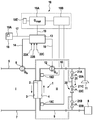
- FIG. 1 is a highly schematic drawing of the essential components of a device according to the invention for extracorporeal blood treatment using a device according to the invention for predetermining an optimum dialysate flow.
- FIG. 2 shows the clearance K (ml/Min) as a function of the dialysate flow Q d (ml/min) for various blood flow rates Q b , and
- FIG. 3 is a flow diagram comprising the method steps for determining an optimum dialysate flow Qd opt by an iterative method.
- FIG. 1 shows an embodiment of a blood treatment device according to the invention which has a device 18 according to the invention for determining an optimum dialysate flow Qd opt .
- FIG. 1 merely shows the essential components of the blood treatment device, since the individual components of a blood treatment device for haemodialysis or haemodiafiltration are generally known to the person skilled in the art.
- the dialysis device has a dialyser 1 , which is subdivided by a semipermeable membrane 2 into a blood chamber 3 and a dialysate chamber 4 .
- An arterial blood line 5 into which a blood pump 6 is connected, leads from a patient to an inlet of the blood chamber 3 , whilst a venous blood line 7 leads from an outlet of the blood chamber 3 of the dialyser 1 to the patient.
- the arterial and venous blood lines 5 , 7 of the extracorporeal blood circuit I are connected to the patient via cannulas (not shown).
- Fresh dialysate is provided in a dialysate source 8 .
- a dialysate supply line 9 leads from the dialysate source 8 to an inlet of the dialysate chamber 4 , whilst a dialysate removal line 10 leads from an outlet of the dialysate chamber 4 of the dialyser 1 to a drain 11 .
- a dialysate pump 12 is connected into the dialysate removal line 10 .
- the dialysate system II of the dialysis device comprises further components, of which only a bypass line 20 comprising a valve arrangement 21 is shown in FIG. 1 , however.
- One end of the bypass line 20 is connected to the dialysate supply line 9 upstream from the dialysate chamber 4 and the other end of the bypass line 20 is connected to the dialysate removal line 10 downstream from the dialysate chamber.
- the valve arrangement 21 comprises two outer valves 21 A and 21 B and a central valve 21 C, which are arranged in the bypass line.
- the dialysis device has a central control unit 13 , which is connected to the blood pump 6 and the dialysate pump 12 via control lines 14 , 15 .
- the control unit 13 generates control signals for operating the blood and dialysate pump 6 , 12 at a predetermined feed rate, in such a way that a predetermined blood flow Q b is established in the blood line 5 , 7 and a predetermined dialysate flow Q d is established in the dialysate line 9 , 10 .
- the valves 21 A, 21 B, 21 C are electromagnetically actuatable valves, which are connected to the control unit 13 via control lines 22 A, 22 B, 22 C.
- the dialysis device has an input unit 16 , which comprises for example an alphanumeric keypad 16 A.
- the input unit 16 is connected via a data line 17 to the control unit 13 , by means of which the individual components of the dialysis device are actuated in such a way that the dialysis treatment is carried out using the predetermined dialysis parameters.
- the dialysis device provides an optimum dialysate flow Q dopt for the dialysis treatment.
- the dialysis device has a device 18 for determining an optimum dialysate flow Q dopt , the construction and operation of which are disclosed in detail in the following.
- the dialysis treatment is carried out using a particular dialyser 1 which has a particular effectiveness.
- the effectiveness of the dialyser 1 is specified by way of the mass transfer coefficient k 0 A, although this does not have to be known to determine the optimum dialysate flow Q dopt .
- the clearance K is calculated from the blood (water) flow Q b and the dialysate flow Q d and the mass transfer coefficient k 0 A of the dialyser 1 using the following equation:
- FIG. 2 shows the clearance K as a function of the dialysate flow Q d for various blood flows Q b . It can be seen that at high dialysate flows Q d the clearance K is saturated. Therefore, from a particular dialysate flow Q dopt upwards, increasing the dialysate flow does not lead to a significant gain in clearance. If the gain in clearance is negligible, a change in the dialysate rate can be omitted or a decrease in the dialysate flow may be expedient. By contrast, if the change in the dialysate rate leads to a significant increase in the clearance, the dialysate rate should be increased.
- the device 18 for determining the optimum dialysate flow Q dopt has a calculation and/or evaluation unit 18 A, which is connected to the central control unit 13 of the blood treatment device via a line 19 in such a way that the calculation and/or evaluation unit 18 A and control unit 13 can receive and transmit control signals or data.
- the device for determining the optimum dialysate flow Q dopt has a measurement device 18 B for measuring a value which is characteristic of the clearance, in particular the dialysate ion concentration at the input and output of the dialysate chamber of the dialyser.
- the measurement device 18 B comprises a conductivity sensor 18 C on the dialysate supply line 9 upstream from the dialysate chamber 2 and a conductivity sensor 18 D on the dialysate removal line 10 downstream from the dialysate chamber 2 of the dialyser 1 , which are merely alluded to in FIG. 1 .
- the measurement of the clearance K is based on the electrolyte concentration being briefly raised or lowered, the conductivity of the dialysate being measured upstream and downstream from the dialysate chamber 2 using the sensors 18 C, 18 D before the change in the electrolyte concentration.
- Measurement devices of this type are known for example from DE 39 38 662 A1 (U.S. Pat. No. 5,100,554) and DE 197 47 360 A1 (U.S. Pat. No. 6,156,002), to which reference is hereby explicitly made. However, it is irrelevant to the invention how the clearance is calculated from the measured values.
- the device 18 predetermines an optimum dialysate flow Q dopt , at which the dialysis device is operated. It is assumed that a particular blood flow Q b is set, which can be inputted at the input unit 16 .
- the calculation and/or evaluation unit 18 A is configured as follows.
- the clearance K is initially measured at the set blood flow Q b for a predetermined dialysate flow Q d .
- the calculation and/or evaluation unit 18 A uses equation (4) to calculate the clearance K from the measured conductivity values before and after the change in the electrolyte concentration.
- the calculation and evaluation unit 18 A calculates the mass transfer coefficient k 0 A of the dialyser 1 using equation (1):
- Q d being the dialysate flow
- Q b being the blood (water) flow
- K being the previously measured clearance
- the dialyser parameter can be determined before or during the dialysis treatment.
- the parameter can be determined at particular time intervals during the dialysis treatment, in such a way that changes in the mass transfer coefficient which are attributable to blocking of the membrane (clotting) can also be taken into account.
- the mass transfer coefficient does not have to be determined during the blood treatment, but can also be determined in advance of the blood treatment during a rinsing process.
- the arterial blood lines 5 is connected to the portion of the bypass line 20 between one outer valve 21 A and the inner valve 21 C, and the venous blood line 7 is connected to the portion of the bypass line 20 between the other outer valve 21 B and the inner valve 21 C, and in the bypass line 20 the outer valves 21 A and 21 B are opened and the middle valve 21 C is closed by the control unit 13 .
- the blood lines 5 , 7 connected to the bypass line 20 for the rinsing process are shown in dashed lines in FIG. 1 .
- a rinsing liquid in particular a dialysate
- a rinsing liquid is supplied to the blood chamber 3 via the dialysate supply line 9 and the portion of the venous blood line 7 and removed from the blood chamber via the portion of the venous blood line 5 and the dialysate removal line 10 .
- the control unit 13 closes the outer valves 21 A, 21 B and opens the central valve 21 C in the bypass line 20 , the blood pump 6 being operated in such a way that the rinsing liquid recirculates through the blood chamber 3 .
- the dialysate pump 12 is operated in such a way that dialysate flows into the dialysate chamber 4 and out of the dialysate chamber 4 .
- the clearance is subsequently determined by the above-described known methods, rinsing liquid, in particular a dialysate, flowing through the blood chamber instead of blood.
- rinsing liquid in particular a dialysate
- the electrolyte concentration of the dialysate flowing into the dialysate chamber 4 is briefly changed, and the response to the concentration bolus is measured in the dialysate flowing out of the dialysate chamber 4 .
- the measurements may also be taken upstream and downstream from the dialyser, for which purpose the conductivity sensors 18 C and 18 D may be used.
- the calculation and/or evaluation unit 18 A calculates the mass transfer coefficient using equation (1). This can be determined for different dialysers and hose line systems. However, when the mass transfer coefficient is calculated using equation (1), it should be taken into account that equation (1) does not precisely describe the actual ratios because of the lower volume of liquid flowing through the blood chamber by comparison with the measurement during the blood treatment and because of the recirculation of the liquid.
- the calculation and/or evaluation unit 18 A therefore makes a correction to the calculated value using an empirically determined correction factor, which takes into account the filling volume of the blood chamber and of the hose line system.
- This correction factor can be determined by laboratory experiments and stored in a memory of the calculation and/or evaluation unit 18 A.
- Q d being the dialysate flow
- Q b being the blood (water) flow
- K o A being the mass transfer coefficient of the dialyser.
- the calculation and/or evaluation unit 18 A can calculate the clearance K for different dialysate flows Qd using equation (1) so as subsequently to find the optimum working point for the dialysis device, as is disclosed in DE 10 2006 045 437 A1.
- the optimum working points for different blood flow rates are marked by circles in FIG. 2 , a ratio of additional dialysate flow [ml/min] and additional clearance [ml/min] of 10:1 having been selected for the working points. If the dialysate rate Q d is increased further starting from the respective working point, an increase in the dialysate rate is no longer associated with a further increase in clearance K which exceeds a particular value.
- the optimum dialysate rate Q dopt is therefore the dialysate flow for which, when it is exceeded, the derivative of the function shown in FIG. 2 , which describes the dependence of the clearance K on the dialysate rate Q d , undershoots a particular critical value.
- a possible but non-optimum working point is denoted A in FIG. 2 .
- the clearance measurement in advance of determining the optimum working point makes it superfluous to determine a three-dimensional curve family, by means of which the optimum dialysate flow rate Q dopt can be determined as a function of the blood flow rate Q b for different dialysers which are each distinguished by a particular mass transfer coefficient K 0 A.
- the device 18 has a display unit 18 E, for example in the form of a screen or a display.
- the device 18 outputs the calculated value for the optimum dialysate flow Q dopt via the line 19 to the control unit 13 of the blood treatment device, which in turn sets the rotational speed of the dialysate pump 12 in such a way that dialysate is conveyed at the optimum dialysate flow Q dopt .
- Another aspect of the invention likewise provides measurement of the clearance to determine an optimal dialysate rate.
- the doctor can predetermine a particular clearance K min which should not be undershot during the blood treatment. However, he can also predetermine a value for the clearance K max which should not be exceeded.
- the clearance K m is measured at a predetermined dialysate flow Q d .
- the calculation and/or evaluation unit 18 A calculates the difference between the measured clearance K m and the predetermined for example minimum clearance K min . If the difference is positive, the calculation and/or evaluation unit 18 A generates a control signal, in such a way that the control unit 13 of the blood treatment device decreases the dialysate flow Q d . By contrast, if the difference is negative, the calculation and/or evaluation unit generates a control signal for the control unit to increase the dialysate flow Q d .
- the amount ⁇ Q d by which the dialysate flow Q d is decreased or increased is proportional to the magnitude of the difference between the measured clearance K m and the minimum clearance K min .
- K m ⁇ K min can also be based on K min (for example (K m ⁇ K min )/K min ⁇ 100%>20%).
- a clearance measurement is taken again so as to be able to establish whether the aim of the treatment is still being achieved.
- the calculation and/or evaluation unit 18 A calculates the difference between the measured clearance K m and the minimum clearance K min . If the difference is still positive, the dialysate flow Q d is decreased again in a further step. By contrast, if the difference is negative the dialysate flow is increased.
- the optimum dialysate flow Q dopt can be determined in a plurality of iterative steps, the dialysate rate being changed by a particular amount, which is proportional to the magnitude of the difference between the measured clearance K m and the minimum clearance K min , in each step.
- the calculation and/or evaluation unit 18 A compares the difference between the measured clearance K m and the minimum clearance K min with a predetermined threshold, which may for example be between 2% and 5% of the minimum clearance K min . If the threshold is achieved or undershot, the calculation and/or evaluation unit 18 A interrupts the iterative process, the currently set dialysate flow Q d being accepted as the optimum dialysate flow Q dopt .
- a further embodiment of the invention for determining the optimum dialysate flow Q dopt by an iterative method which is based on measuring the clearance K is disclosed in the following.
- the control unit 13 initially generates a control signal, which predetermines a dialysate flow Q d,1 corresponding to the blood flow Q b .
- the clearance K 1 is measured at the predetermined blood flow Q b and dialysate flow Q d,1 , it again being possible to determine the clearance by the above-disclosed method.
- the control unit subsequently increases the dialysate flow Q d,1 , by the amount ⁇ Q d , for example by 50 ml/min, to Q d,2 .
- the clearance is measured again at the blood flow Q b with result K 2 .
- the two measurements are subsequently evaluated by the calculation and/or evaluation unit 18 A as follows.
- the change in the clearance of K 1 and K 2 as a result of the change in the dialysate flow by ⁇ Q d12 from Q d,1 to Q d,2 is checked by the calculation and/or evaluation unit 18 A as to whether a criterion is met for increasing or decreasing or maintaining the dialysate flow Q d .
- the calculation and/or evaluation unit compares the gradient ⁇ K 12 / ⁇ Q d12 of the relative change in the clearance and in the relative dialysate flow with a first threshold c 1 and a second threshold c 2 , the first threshold being greater than the second threshold.
- the second threshold may also be equal to the first threshold.
- the calculation and control unit 13 If the gradient ⁇ K 12 / ⁇ Q d12 is greater than the first threshold c 1 , the calculation and control unit 13 generates a control signal to increase the dialysate flow Q d , in such a way that the dialysate flow Q d is further increased by ⁇ Q d .
- the calculation and control unit 13 If the gradient ⁇ K 12 / ⁇ Q d12 is less than the second threshold c 2 , the calculation and control unit 13 generates a control signal to decrease the dialysate flow Q d , in such a way that the dialysate flow Q d is decreased by ⁇ Q d again.
- a control signal to maintain the dialysate flow Q d is generated, in such a way that the optimum dialysate flow Q dopt is determined and is also set.
- the clearance K is measured again, so as to be able to check again the change in the clearance from the previously measured value to the current value as a result of the increase or decrease in the dialysate flow for whether the above criterion is met. This process is continued until the gradient ⁇ K 12 / ⁇ Q d12 is less than the first threshold and greater than the second threshold and the dialysate flow is no longer being changed.
- the device according to the invention and the method according to the invention aim to optimise the dialysate flow on the basis of the determination of the diffusive component of the dialyser clearance.
- the device according to the invention and the method according to the invention can be used for determining an optimum dialysate flow not only for haemodialysis (HD), but also for haemodiafiltration (HDF).
- haemodiafiltration the following values occur:
- the clearance calculated to determine the optimum dialysate flow Q d,opt is dependent on the dialysate flow Q d and the blood flow Q b , and is denoted as K d (Q d , Q b , K o A).
- haemolysis haemodialysis
- HDF pre-dilution haemodiafiltration with pre-dilution
- the diffusive exchange in the dialyser thus takes place for the total flow:
- K m , diff Q bw + ⁇ ⁇ Q s Q b - Q f - ( 1 - ⁇ ) ⁇ Q s ⁇ ( Q bw + ⁇ ⁇ Q s Q b ⁇ K m - Q f - Q s ) ,
- K m , diff Q b Q b - Q f - Q s ⁇ ( K m - Q f - Q s )
- the clearance can be calculated using the following equation.
- the calculation and/or evaluation unit 18 A calculates the clearance as follows once the dialysate input concentrations c di (1) and c di (2) and dialysate output concentrations c do (1) and c do (2) have been measured:
- K m , tot ( Q d + Q f + Q s ) ⁇ ( 1 - c do ⁇ ( 2 ) - c do ⁇ ( 1 ) c di ⁇ ( 2 ) - c di ⁇ ( 1 ) ) equation ⁇ ⁇ ( 4 ′ )
- Q f being the total filtration rate, in other words the total of the ultrafiltration rate Q UF and the substituate rate Q S .
- dialysate input concentrations c di (1) and c di (2) and dialysate output concentrations c do (1) and c do (2) are varied continuously (pulse profile) rather than incrementally (stepped profile), the clearance is calculated as follows:
- K m , tot ( Q d + Q s + Q f ) ⁇ ( 1 - ⁇ t 2 t 3 ⁇ ⁇ ⁇ ⁇ c do ⁇ ( t ′ ) ⁇ dt ′ ⁇ ⁇ t 0 t 1 ⁇ ⁇ ⁇ ⁇ c di ⁇ ( t ′ ) ⁇ dt ′ )
Landscapes
- Health & Medical Sciences (AREA)
- Heart & Thoracic Surgery (AREA)
- Urology & Nephrology (AREA)
- Hematology (AREA)
- Animal Behavior & Ethology (AREA)
- Engineering & Computer Science (AREA)
- Anesthesiology (AREA)
- Biomedical Technology (AREA)
- Veterinary Medicine (AREA)
- Life Sciences & Earth Sciences (AREA)
- Vascular Medicine (AREA)
- General Health & Medical Sciences (AREA)
- Public Health (AREA)
- Emergency Medicine (AREA)
- Physics & Mathematics (AREA)
- Fluid Mechanics (AREA)
- External Artificial Organs (AREA)
Abstract
Description
Qd being the dialysate flow, Qb being the blood (water) flow and K being the measured clearance.
dK(Q d)/dQ d<crit1 equation (3.1)
Q d is decreased
crit1 <dK(Q d)/dQ d<crit2 equation (3.2)
Q d is not changed
dK(Q d)/dQ d<crit2 equation (3.3)
Q d is increased
K=Q d(((c di(1)−c do(1))−(c di(2)−c do(2)))/(c di(1)−c di(2)) equation (4)
ΔK 12 /ΔQ d12=(K2−K1)/(Q d,2 −Q d,1) equation (5)
- KoA: diffusive mass transfer coefficient or coefficient of diffusive mass transfer, which takes into account the diffusive component of the dialyser clearance;
- Qd: dialysate flow through the dialyser, which is to be distinguished from the total flow of the dialysate Qd,tot, which is the sum (Qd,tot=Qd+Qs) of the dialysate flow Qd through the dialyser and the substituate flow Qs;
- Qd,opt optimum dialysate flow;
- Qbw: blood water flow at the arterial cannula. The blood flow at the dialyser input is increased by supplying substituate upstream from the dialyser (pre-dilution), whilst the blood flow at the dialyser output is decreased by ultrafiltration and by supplying substituate downstream from the dialyser (post-dilution). The blood water flow Qbw is dependent on the haematocrit and the protein content in the blood, Qbw being approximately 0.86 Qb;
- Km,tot: measured system clearance, which comprises the total purification power of the system including the convective and diffusive component of the clearance, patient effects which decrease the clearance, for example recirculation, being taken into account;
- Km,diff: diffusive component of the system clearance, which is derived from the measured system clearance Km,tot and is based on the calculation of the diffusive mass transfer coefficient KoA.
- κ=1 for HDF pre-dilution
- κ=0 for HD and HDF post-dilution
which, in the case of haemodialysis or HDF post-dilution where κ=0, gives:
- Δcj being the height of the LF variation above the base line.
Claims (8)
Applications Claiming Priority (4)
| Application Number | Priority Date | Filing Date | Title |
|---|---|---|---|
| DE102014011699.9 | 2014-08-07 | ||
| DE102014011699 | 2014-08-07 | ||
| DE102014011699.9A DE102014011699B4 (en) | 2014-08-07 | 2014-08-07 | Device for determining an optimal dialysate flow for extracorporeal blood treatment with an extracorporeal blood treatment device |
| PCT/EP2015/066582 WO2016020180A1 (en) | 2014-08-07 | 2015-07-20 | Device and method for determining an optimum dialysate flow for an extracorporeal blood treatment with an extracorporeal blood treatment device |
Publications (2)
| Publication Number | Publication Date |
|---|---|
| US20170224897A1 US20170224897A1 (en) | 2017-08-10 |
| US10569001B2 true US10569001B2 (en) | 2020-02-25 |
Family
ID=53673955
Family Applications (1)
| Application Number | Title | Priority Date | Filing Date |
|---|---|---|---|
| US15/501,180 Active 2035-11-06 US10569001B2 (en) | 2014-08-07 | 2015-07-20 | Device and method for determining an optimum dialysate flow for an extracorporeal blood treatment with an extracorporeal blood treatment device |
Country Status (4)
| Country | Link |
|---|---|
| US (1) | US10569001B2 (en) |
| EP (1) | EP3177336B1 (en) |
| DE (1) | DE102014011699B4 (en) |
| WO (1) | WO2016020180A1 (en) |
Families Citing this family (10)
| Publication number | Priority date | Publication date | Assignee | Title |
|---|---|---|---|---|
| EP3539586B1 (en) | 2014-10-10 | 2022-08-24 | NxStage Medical Inc. | Flow balancing methods |
| EP3484536B1 (en) | 2016-07-18 | 2022-04-27 | NxStage Medical Inc. | Flow balancing devices, methods, and systems |
| EP3506962B1 (en) | 2016-08-30 | 2023-11-22 | NxStage Medical, Inc. | Parameter monitoring in medical treatment systems |
| JP6997582B2 (en) * | 2017-10-17 | 2022-01-17 | 日機装株式会社 | Blood purification device |
| CA3138773A1 (en) | 2019-05-23 | 2020-11-26 | Nxstage Medical, Inc. | Flow synchronization devices, methods and systems |
| DE102023100665A1 (en) * | 2023-01-12 | 2024-07-18 | Fresenius Medical Care Deutschland Gmbh | Control or regulating device for a blood treatment device for controlling clearance during dialysis |
| CN116162680A (en) * | 2023-03-03 | 2023-05-26 | 山东威高血液净化制品股份有限公司 | Method for quantitatively evaluating thrombus degree of blood purification device |
| US20250018098A1 (en) * | 2023-07-10 | 2025-01-16 | Fresenius Medical Care Holdings, Inc. | Dialysis Treatment and Machine |
| US20250018099A1 (en) * | 2023-07-10 | 2025-01-16 | Fresenius Medical Care Holdings, Inc. | Dialysis Treatment and Machine |
| DE102024103671A1 (en) | 2024-02-09 | 2025-08-14 | B.Braun Avitum Ag | Procedure, dialysis machine and dialysis system |
Citations (8)
| Publication number | Priority date | Publication date | Assignee | Title |
|---|---|---|---|---|
| US5100554A (en) | 1989-11-21 | 1992-03-31 | Fresenius Ag | Method for the in-vivo determination of hemodialysis parameters |
| WO2007140993A1 (en) | 2006-06-08 | 2007-12-13 | Fresenius Medical Care Deutschland Gmbh | Device and method for controlling an extracorporeal blood treatment device |
| US20100042035A1 (en) | 2006-09-26 | 2010-02-18 | Ulrich Moissl | Device and method for determining a dialysis fluid flow rate for extracorporeal blood treatment |
| EP2514449A1 (en) | 2009-12-17 | 2012-10-24 | Nipro Corporation | Hemodialysis device |
| US20120298581A1 (en) | 2011-05-23 | 2012-11-29 | Fresenius Medical Care Deutschland Gmbh | Device and method for detecting an operating state of an extracorporeal blood treatment |
| US20130020237A1 (en) * | 2007-02-27 | 2013-01-24 | Deka Products Limited Partnership | Blood treatment systems and methods |
| US20130303964A1 (en) | 2012-05-10 | 2013-11-14 | Fresenius Medical Care Deutschland Gmbh | Apparatus for extra-corporeal blood treatment and method of determining a blood flow rate for an extra-corporeal blood treatment apparatus |
| US20140248600A1 (en) * | 2011-05-27 | 2014-09-04 | Gambro Lundia Ab | Blood treatment apparatus adapted to preserve parts thereof |
Family Cites Families (4)
| Publication number | Priority date | Publication date | Assignee | Title |
|---|---|---|---|---|
| DE3909967A1 (en) | 1989-03-25 | 1990-09-27 | Fresenius Ag | HAEMODIALYSIS DEVICE WITH AUTOMATIC ADJUSTMENT OF THE DIALYSIS FLUID FLOW |
| DE19747360B8 (en) | 1997-10-27 | 2007-05-16 | Fresenius Medical Care De Gmbh | Method for measuring performance parameters of mass and energy exchange modules |
| JP5042839B2 (en) * | 2005-09-09 | 2012-10-03 | 有限会社ケムフィズ | Medicament for prevention and / or treatment of bowel disease |
| US8936620B2 (en) * | 2008-07-21 | 2015-01-20 | Pivot Medical, Inc. | Method and apparatus for securing soft tissue to bone |
-
2014
- 2014-08-07 DE DE102014011699.9A patent/DE102014011699B4/en active Active
-
2015
- 2015-07-20 US US15/501,180 patent/US10569001B2/en active Active
- 2015-07-20 WO PCT/EP2015/066582 patent/WO2016020180A1/en not_active Ceased
- 2015-07-20 EP EP15738931.3A patent/EP3177336B1/en active Active
Patent Citations (11)
| Publication number | Priority date | Publication date | Assignee | Title |
|---|---|---|---|---|
| US5100554A (en) | 1989-11-21 | 1992-03-31 | Fresenius Ag | Method for the in-vivo determination of hemodialysis parameters |
| WO2007140993A1 (en) | 2006-06-08 | 2007-12-13 | Fresenius Medical Care Deutschland Gmbh | Device and method for controlling an extracorporeal blood treatment device |
| US20100168925A1 (en) | 2006-06-08 | 2010-07-01 | Peter Hilgers | Device and method for controlling an extracorporeal blood- treating apparatus |
| US20100042035A1 (en) | 2006-09-26 | 2010-02-18 | Ulrich Moissl | Device and method for determining a dialysis fluid flow rate for extracorporeal blood treatment |
| US20130020237A1 (en) * | 2007-02-27 | 2013-01-24 | Deka Products Limited Partnership | Blood treatment systems and methods |
| EP2514449A1 (en) | 2009-12-17 | 2012-10-24 | Nipro Corporation | Hemodialysis device |
| US20120298581A1 (en) | 2011-05-23 | 2012-11-29 | Fresenius Medical Care Deutschland Gmbh | Device and method for detecting an operating state of an extracorporeal blood treatment |
| DE102011102962A1 (en) | 2011-05-23 | 2012-11-29 | Fresenius Medical Care Deutschland Gmbh | Device and method for detecting an operating state of an extracorporeal blood treatment |
| US20140248600A1 (en) * | 2011-05-27 | 2014-09-04 | Gambro Lundia Ab | Blood treatment apparatus adapted to preserve parts thereof |
| US20130303964A1 (en) | 2012-05-10 | 2013-11-14 | Fresenius Medical Care Deutschland Gmbh | Apparatus for extra-corporeal blood treatment and method of determining a blood flow rate for an extra-corporeal blood treatment apparatus |
| WO2013167264A1 (en) | 2012-05-10 | 2013-11-14 | Fresenius Medical Care Deutschland Gmbh | Extracorporeal blood treatment device and method for ascertaining a blood flow rate for an extracorporeal blood treatment device |
Non-Patent Citations (2)
| Title |
|---|
| International Preliminary Report on Patentability for corresponding International Patent Application No. PCT/EP2015/066582, dated Feb. 7, 2017, with corresponding Form PCT/IB/338 and Written Opinion of the International Searching Authority (Form PCT/ISA/237) (7 pages total). |
| International Search Report and Written Opinion issued in corresponding International Patent Application No. PCT/EP2015/066582 (with English translation of International Search Report) dated Oct. 9, 2015 (12 pages). |
Also Published As
| Publication number | Publication date |
|---|---|
| US20170224897A1 (en) | 2017-08-10 |
| DE102014011699B4 (en) | 2023-11-02 |
| EP3177336B1 (en) | 2020-03-11 |
| DE102014011699A1 (en) | 2016-02-11 |
| EP3177336A1 (en) | 2017-06-14 |
| WO2016020180A1 (en) | 2016-02-11 |
Similar Documents
| Publication | Publication Date | Title |
|---|---|---|
| US10569001B2 (en) | Device and method for determining an optimum dialysate flow for an extracorporeal blood treatment with an extracorporeal blood treatment device | |
| US9925321B2 (en) | Apparatus for extracorporeal blood treatment | |
| US6730233B2 (en) | Device and method for controlling infusion of liquid in an extracorporeal blood circuit | |
| US9220830B2 (en) | Apparatus for extracorporeal blood treatment | |
| US9199027B2 (en) | Apparatus for extracorporeal blood treatment | |
| JP5395666B2 (en) | Apparatus and method for determining dialysate flow rate and blood flow rate in extracorporeal blood treatment | |
| CN107666919B (en) | Equipment for extracorporeal blood treatment | |
| CA2707774C (en) | Method and device for determining the transmembrane pressure in an extracorporeal blood treatment | |
| CN107666918B (en) | Device for extracorporeal blood treatment | |
| WO2005063320A1 (en) | Method and apparatus for determining a patient or treatment or apparatus parameter during an extracorporeal blood treatment | |
| US11872335B2 (en) | Apparatus for extracorporeal blood treatment | |
| CN110225773B (en) | Device for extracorporeal blood processing | |
| CN113260391B (en) | Device for extracorporeal blood treatment | |
| CN117479966A (en) | Equipment for extracorporeal blood processing |
Legal Events
| Date | Code | Title | Description |
|---|---|---|---|
| AS | Assignment |
Owner name: FRESENIUS MEDICAL CARE DEUTSCHLAND GMBH, GERMANY Free format text: ASSIGNMENT OF ASSIGNORS INTEREST;ASSIGNORS:KOPPERSCHMIDT, PASCAL;MAIERHOFER, ANDREAS;GAGEL, ALFRED;AND OTHERS;SIGNING DATES FROM 20170117 TO 20170119;REEL/FRAME:041154/0746 |
|
| STPP | Information on status: patent application and granting procedure in general |
Free format text: ADVISORY ACTION MAILED |
|
| STPP | Information on status: patent application and granting procedure in general |
Free format text: DOCKETED NEW CASE - READY FOR EXAMINATION |
|
| STPP | Information on status: patent application and granting procedure in general |
Free format text: NON FINAL ACTION MAILED |
|
| STPP | Information on status: patent application and granting procedure in general |
Free format text: RESPONSE TO NON-FINAL OFFICE ACTION ENTERED AND FORWARDED TO EXAMINER |
|
| STPP | Information on status: patent application and granting procedure in general |
Free format text: NOTICE OF ALLOWANCE MAILED -- APPLICATION RECEIVED IN OFFICE OF PUBLICATIONS |
|
| STPP | Information on status: patent application and granting procedure in general |
Free format text: NOTICE OF ALLOWANCE MAILED -- APPLICATION RECEIVED IN OFFICE OF PUBLICATIONS |
|
| STPP | Information on status: patent application and granting procedure in general |
Free format text: PUBLICATIONS -- ISSUE FEE PAYMENT VERIFIED |
|
| STCF | Information on status: patent grant |
Free format text: PATENTED CASE |
|
| MAFP | Maintenance fee payment |
Free format text: PAYMENT OF MAINTENANCE FEE, 4TH YEAR, LARGE ENTITY (ORIGINAL EVENT CODE: M1551); ENTITY STATUS OF PATENT OWNER: LARGE ENTITY Year of fee payment: 4 |