US10566688B2 - Horn antenna module and antenna cover thereof - Google Patents
Horn antenna module and antenna cover thereof Download PDFInfo
- Publication number
- US10566688B2 US10566688B2 US15/926,967 US201815926967A US10566688B2 US 10566688 B2 US10566688 B2 US 10566688B2 US 201815926967 A US201815926967 A US 201815926967A US 10566688 B2 US10566688 B2 US 10566688B2
- Authority
- US
- United States
- Prior art keywords
- protrusion
- waveguide
- top surface
- projection plane
- protrusions
- Prior art date
- Legal status (The legal status is an assumption and is not a legal conclusion. Google has not performed a legal analysis and makes no representation as to the accuracy of the status listed.)
- Active, expires
Links
Images


Classifications
-
- H—ELECTRICITY
- H01—ELECTRIC ELEMENTS
- H01Q—ANTENNAS, i.e. RADIO AERIALS
- H01Q1/00—Details of, or arrangements associated with, antennas
- H01Q1/02—Arrangements for de-icing; Arrangements for drying-out ; Arrangements for cooling; Arrangements for preventing corrosion
-
- H—ELECTRICITY
- H01—ELECTRIC ELEMENTS
- H01Q—ANTENNAS, i.e. RADIO AERIALS
- H01Q1/00—Details of, or arrangements associated with, antennas
- H01Q1/42—Housings not intimately mechanically associated with radiating elements, e.g. radome
-
- H—ELECTRICITY
- H01—ELECTRIC ELEMENTS
- H01Q—ANTENNAS, i.e. RADIO AERIALS
- H01Q13/00—Waveguide horns or mouths; Slot antennas; Leaky-waveguide antennas; Equivalent structures causing radiation along the transmission path of a guided wave
- H01Q13/02—Waveguide horns
-
- H—ELECTRICITY
- H01—ELECTRIC ELEMENTS
- H01Q—ANTENNAS, i.e. RADIO AERIALS
- H01Q13/00—Waveguide horns or mouths; Slot antennas; Leaky-waveguide antennas; Equivalent structures causing radiation along the transmission path of a guided wave
- H01Q13/02—Waveguide horns
- H01Q13/0241—Waveguide horns radiating a circularly polarised wave
-
- H—ELECTRICITY
- H01—ELECTRIC ELEMENTS
- H01Q—ANTENNAS, i.e. RADIO AERIALS
- H01Q13/00—Waveguide horns or mouths; Slot antennas; Leaky-waveguide antennas; Equivalent structures causing radiation along the transmission path of a guided wave
- H01Q13/02—Waveguide horns
- H01Q13/025—Multimode horn antennas; Horns using higher mode of propagation
Definitions
- the present invention relates to an antenna cover, and in particular to an antenna cover of a horn antenna module.
- the free end of a waveguide of a horn antenna is covered by an antenna cover.
- the antenna cover prevents water from entering the wave guide, and prevents the convertor of the horn antenna from being damaged by water.
- Conventional antenna covers are planar, and are made of materials that have a low dielectric coefficient (for example, polypropylene).
- a low dielectric coefficient for example, polypropylene.
- the performance (such as cross polarization) of the horn antenna is affected, and the signal transmission of the horn antenna deteriorates.
- an antenna cover with one single protrusion is provided to increase the strength of the antenna cover, and to prevent deformation.
- the antenna cover with a single protrusion cannot optimize the signal transmission of each horn antenna on the horn antenna module (for example, one horn antenna module may have one low-band horn antenna and two high-band horn antennae).
- the performance of the horn antennas located on lateral sides of the horn antenna module may become deteriorated.
- a horn antenna module in one embodiment, includes a waveguide and an antenna cover.
- the waveguide includes a plurality of waveguide paths.
- the antenna cover covers one end of the waveguide.
- the antenna cover includes a plurality of protrusions and a bottom surface.
- the protrusions are formed on the bottom surface.
- the protrusions correspond one-to-one with the waveguide paths.
- Each protrusion has a top surface and a lateral surface. The lateral surface is located between the top surface and the bottom surface. The top surface is planar.
- the lateral surface forms a first side and a second side on a cross section, the cross section is perpendicular to the bottom surface, and the first side and the second side are straight lines.
- the lateral surface forms a first side and a second side on a cross section, the cross section is perpendicular to the bottom surface, and the first side and the second side are curves with the same radius.
- the protrusions comprise a first protrusion, a second protrusion and a third protrusion
- the waveguide paths comprise a first waveguide path, a second waveguide path and a third waveguide path
- the first protrusion corresponds to the first waveguide path
- the second protrusion corresponds to the second waveguide path
- the third protrusion corresponds to the third waveguide path
- the first protrusion is located between the second protrusion and the third protrusion
- the first waveguide path transmits a low-band signal
- the second waveguide path and the third waveguide path transmit a high-band signal.
- the top surface of the first protrusion projects a first circular area on a projection plane
- the projection plane is parallel to the bottom surface
- the first protrusion projects an elliptical area on the projection plane
- the ratio of the diameter of the first circular area to the major axis of the elliptical area is between 0.05:1 and 0.4:1.
- the top surface of the second protrusion projects a second circular area on the projection plane
- the second protrusion projects a third circular area on the projection plane
- the ratio of the diameter of the second circular area to the diameter of the third circular area is between 0.1:1 and 0.6:1.
- the height of the first protrusion differs from that of the second protrusion and of the third protrusion.
- the first waveguide path comprises a tube-shaped section and a cone-shaped section, one end of the tube-shaped section is connected to a narrow end of the cone-shaped section, a distance is formed between the narrow end and the top surface of the first protrusion, and the distance is equal to a quarter of the wavelength of the low-band signal.
- each protrusion comprises a material feed feature, and the material feed feature is formed on the lateral surface.
- the waveguide path projects a path area on a projection plane, the projection plane is parallel to the bottom surface, and a projection of the material feed feature on the projection plane is out of the path area.
- the material feed feature is a recess.
- an antenna cover covers an end of a waveguide.
- the antenna cover includes a plurality of protrusions and a bottom surface.
- the protrusions are formed on the bottom surface, each protrusion has a top surface and a lateral surface.
- the lateral surface is located between the top surface and the bottom surface.
- the top surface is planar.
- the protrusions increase the strength of the antenna cover.
- the antenna cover therefore can resist the difference between the environmental pressure and the inner pressure of the horn antennas due to temperature change.
- the antenna cover is prevented from deforming, and the thickness of the antenna cover is reduced.
- the radio frequency (RF) performance of the horn antenna module is therefore improved.
- the shape of each protrusion can be optimized according to the corresponding waveguide to improve the performance of the horn antenna module.
- the cross polarization of the converter utilizing the antenna cover of the embodiment of the invention can be more than 23 dB (full band).
- FIG. 1 is a sectional view of a horn antenna module of a first embodiment of the invention
- FIG. 2A is a perspective view of the antenna cover of the first embodiment of the invention.
- FIG. 2B is a sectional view along 2 B- 2 B direction of the antenna cover of the FIG. 2A of the embodiment of the invention
- FIG. 2C is a top view of the antenna cover of the FIG. 2A of the embodiment of the invention.
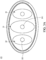
- FIG. 3A shows an antenna cover of a second embodiment of the invention
- FIG. 3B shows an antenna cover of a third embodiment of the invention
- FIG. 3C shows an antenna cover of a fourth embodiment of the invention
- FIG. 4A shows an antenna cover of a fifth embodiment of the invention.
- FIG. 4B is a sectional view along 4 B- 4 B direction of the antenna cover of the FIG. 4A of the embodiment of the invention.
- FIG. 1 is a sectional view of a horn antenna module A of a first embodiment of the invention.
- the horn antenna module A of the first embodiment of the invention includes a waveguide G and an antenna cover C 1 .
- the waveguide G includes a plurality of waveguide paths 10 .
- the antenna cover C 1 covers one end of the waveguide G.
- the antenna cover C 1 includes a plurality of protrusions 20 and a bottom surface 24 .
- the protrusions 20 are formed on the bottom surface 24 .
- the protrusions 20 correspond one-to-one with the waveguide paths 10 .
- FIG. 2A is a perspective view of the antenna cover C 1 of the first embodiment of the invention.
- the protrusions 20 comprise a first protrusion 21 , a second protrusion 22 and a third protrusion 23 .
- the waveguide paths 10 comprise a first waveguide path 11 , a second waveguide path 12 and a third waveguide path 13 .
- the first protrusion 21 corresponds to the first waveguide path 11 .
- the second protrusion 22 corresponds to the second waveguide path 12 .
- the third protrusion 23 corresponds to the third waveguide path 13 .
- the first protrusion 21 is located between the second protrusion 22 and the third protrusion 23 .
- the first waveguide path 11 belongs to a first horn antenna to transmit a low-band signal
- the second waveguide path 12 belongs to a second horn antenna
- the third waveguide path 13 belongs to a third horn antenna to transmit a high-band signal
- each protrusion 20 has a top surface 211 and a lateral surface 212 .
- the lateral surface 212 is located between the top surface 211 and the bottom surface 24 .
- the top surface 211 is planar.
- the top surface of the protrusion is planar.
- the thickness of the top portion of the protrusion is decreased, and the radio frequency (RF) performance of the horn antenna module can be improved.
- FIG. 2B is a sectional view along 2 B- 2 B direction of the antenna cover C 1 of the FIG. 2A of the embodiment of the invention.
- the lateral surface 212 forms a first side 213 and a second side 214 on a cross section.
- the cross section is perpendicular to the bottom surface.
- the first side 213 and the second side 214 are straight lines.
- FIG. 2C is a top view of the antenna cover C 1 of the FIG. 2A of the embodiment of the invention.
- the top surface 211 of the first protrusion 21 projects a first circular area on a projection plane (the projection plane is parallel to the bottom surface 24 ).
- the first protrusion 21 projects an elliptical area on the projection plane.
- the ratio of the diameter ⁇ 1 of the first circular area to the major axis ⁇ 2 of the elliptical area is between 0.05:1 and 0.4:1.
- the top surface 221 of the second protrusion 22 projects a second circular area on the projection plane.
- the second protrusion 22 projects a third circular area on the projection plane.
- the ratio of the diameter ⁇ 3 of the second circular area to the diameter ⁇ 4 of the third circular area is between 0.1:1 and 0.6:1.
- the height of the first protrusion is greater than the heights of the second protrusion and the third protrusion.
- the disclosure is not meant to restrict the invention.
- the heights of the first protrusion, the second protrusion and the third protrusion can be modified.
- the height of the first protrusion can be the same with the heights of the second protrusion and the third protrusion.
- the first waveguide path 11 comprises a tube-shaped section 111 and a cone-shaped section 112 .
- One end of the tube-shaped section 111 is connected to the narrow end of the cone-shaped section 112 .
- a distance h 1 is formed between the narrow end and the top surface 211 of the first protrusion 21 .
- the distance h 1 is equal to a quarter of the wavelength of the low-band signal.
- each protrusion 20 comprises a material feed feature 28 .
- the material feed feature 28 is formed on the lateral surface. Taking the first protrusion 21 as an example, the material feed feature 28 is formed on the lateral surface 212 .
- the material feed feature 28 corresponds to an inlet of a mold for forming the antenna cover.
- the material feed feature 28 is a circular recess.
- the material feed feature 28 can also be other shapes.
- the material feed feature 28 is not formed on the top surface of the protrusion, the thickness of the top portion of the protrusion is therefore decreased, and the radio frequency (RF) performance of the horn antenna module can be improved.
- RF radio frequency
- the first waveguide path 11 projects a path area 113 on the projection plane.
- the projection of the material feed feature 28 on the projection plane is out of the path area 113 .
- the projection of the material feed feature 28 on the projection plane is out of the path area 113 to reduce the signal interference caused by the material feed feature 28 .
- the disclosure is not meant to restrict the invention, in other embodiment, for example, the size of the antenna cover being too small, the projection of the material feed feature 28 on the projection plane maybe inside of the path area 113 .
- FIG. 3A shows an antenna cover C 2 of a second embodiment of the invention.
- the second protrusion 22 and the third protrusion 23 project elliptical areas on the projection plane.
- FIG. 3B shows an antenna cover C 3 of a third embodiment of the invention.
- FIG. 3B shows an antenna cover C 3 of a fourth embodiment of the invention.
- FIG. 3C shows an antenna cover C 4 of a fourth embodiment of the invention.
- each top surface of each protrusion projects an elliptical area on the projection plane. According to the embodiments above, the shape of the projection areas of the protrusions and the top surfaces of the protrusions can the modified.
- FIGS. 4A and 4B show an antenna cover C 5 of a fifth embodiment of the invention.
- the lateral surface 212 forms a first side 213 and a second side 214 on a cross section (the cross section is perpendicular to the bottom surface), and the first side 213 and the second side 214 are curves with the same radius.
- the height of the first protrusion 21 differs from heights of the second protrusion 22 and the third protrusion 23 .
- the protrusions increase the strength of the antenna cover.
- the antenna cover therefore can resist the difference between the environmental pressure and the inner pressure of the horn antennas due to temperature change.
- the antenna cover is prevented from deforming, and the thickness of the antenna cover is reduced.
- the radio frequency (RF) performance of the horn antenna module is therefore improved.
- the shape of each protrusion can be optimized according to the corresponding waveguide to improve the performance of the horn antenna module.
- the cross polarization of the converter utilizing the antenna cover of the embodiment of the invention can be more than 23 dB (full band).
Landscapes
- Waveguide Aerials (AREA)
Abstract
Description
Claims (14)
Applications Claiming Priority (3)
| Application Number | Priority Date | Filing Date | Title |
|---|---|---|---|
| TW106140100 | 2017-11-20 | ||
| TW106140100A TWI663786B (en) | 2017-11-20 | 2017-11-20 | Horn antenna and antenna cover thereof |
| TW106140100A | 2017-11-20 |
Publications (2)
| Publication Number | Publication Date |
|---|---|
| US20190157750A1 US20190157750A1 (en) | 2019-05-23 |
| US10566688B2 true US10566688B2 (en) | 2020-02-18 |
Family
ID=66533335
Family Applications (1)
| Application Number | Title | Priority Date | Filing Date |
|---|---|---|---|
| US15/926,967 Active 2038-04-27 US10566688B2 (en) | 2017-11-20 | 2018-03-20 | Horn antenna module and antenna cover thereof |
Country Status (2)
| Country | Link |
|---|---|
| US (1) | US10566688B2 (en) |
| TW (1) | TWI663786B (en) |
Families Citing this family (2)
| Publication number | Priority date | Publication date | Assignee | Title |
|---|---|---|---|---|
| JP7103860B2 (en) * | 2017-06-26 | 2022-07-20 | 日本電産エレシス株式会社 | Horn antenna array |
| USD876401S1 (en) * | 2017-11-20 | 2020-02-25 | Wistron Neweb Corp. | Horn antenna |
Citations (6)
| Publication number | Priority date | Publication date | Assignee | Title |
|---|---|---|---|---|
| CN1047170A (en) | 1989-01-11 | 1990-11-21 | 麦克罗皮恩公司 | Multimode dielectric-loaded multi-flare antenna |
| US6501432B2 (en) | 2000-08-11 | 2002-12-31 | Alps Electric Co., Ltd. | Primary radiator capable of achieving both low reflection and low loss |
| EP2584652A1 (en) | 2011-10-21 | 2013-04-24 | Siemens Aktiengesellschaft | Horn antenna for a radar device |
| CN203434286U (en) | 2013-06-14 | 2014-02-12 | 西安希德电子信息技术有限公司 | BD2 B3 five-unit satellite navigation anti-interference antenna |
| US20150009083A1 (en) * | 2013-04-03 | 2015-01-08 | Prime Electronics And Satellitics Incorporation | Feed horn having dielectric layers and assembly of feed horn and radome |
| US9379457B2 (en) | 2013-04-03 | 2016-06-28 | Prime Electronics And Satellitics Incorporation | Radome for feed horn and assembly of feed horn and radome |
Family Cites Families (1)
| Publication number | Priority date | Publication date | Assignee | Title |
|---|---|---|---|---|
| JP4000359B2 (en) * | 2003-05-13 | 2007-10-31 | 島田理化工業株式会社 | Primary radiator for parabolic antenna |
-
2017
- 2017-11-20 TW TW106140100A patent/TWI663786B/en active
-
2018
- 2018-03-20 US US15/926,967 patent/US10566688B2/en active Active
Patent Citations (7)
| Publication number | Priority date | Publication date | Assignee | Title |
|---|---|---|---|---|
| CN1047170A (en) | 1989-01-11 | 1990-11-21 | 麦克罗皮恩公司 | Multimode dielectric-loaded multi-flare antenna |
| US6501432B2 (en) | 2000-08-11 | 2002-12-31 | Alps Electric Co., Ltd. | Primary radiator capable of achieving both low reflection and low loss |
| EP2584652A1 (en) | 2011-10-21 | 2013-04-24 | Siemens Aktiengesellschaft | Horn antenna for a radar device |
| US20130099989A1 (en) * | 2011-10-21 | 2013-04-25 | Siemens Aktiengesellschaft | Horn Antenna For A Radar Device |
| US20150009083A1 (en) * | 2013-04-03 | 2015-01-08 | Prime Electronics And Satellitics Incorporation | Feed horn having dielectric layers and assembly of feed horn and radome |
| US9379457B2 (en) | 2013-04-03 | 2016-06-28 | Prime Electronics And Satellitics Incorporation | Radome for feed horn and assembly of feed horn and radome |
| CN203434286U (en) | 2013-06-14 | 2014-02-12 | 西安希德电子信息技术有限公司 | BD2 B3 five-unit satellite navigation anti-interference antenna |
Also Published As
| Publication number | Publication date |
|---|---|
| TWI663786B (en) | 2019-06-21 |
| US20190157750A1 (en) | 2019-05-23 |
| TW201924147A (en) | 2019-06-16 |
Similar Documents
| Publication | Publication Date | Title |
|---|---|---|
| US20120098706A1 (en) | Antenna Module and Antenna Unit Thereof | |
| US8362958B2 (en) | Aperture antenna | |
| US8242966B2 (en) | Antenna array | |
| WO2016136927A1 (en) | Antenna apparatus | |
| US11050158B2 (en) | Dielectric lens | |
| US10938100B2 (en) | Dual-feed loop antenna structure and electronic device | |
| US11011849B2 (en) | Antenna structure | |
| US20100066624A1 (en) | Spiral antenna | |
| US10573967B2 (en) | Antenna structure | |
| EP2565984B1 (en) | Primary radiator and antenna apparatus | |
| US10566688B2 (en) | Horn antenna module and antenna cover thereof | |
| US11081785B2 (en) | Antenna module | |
| US9024821B2 (en) | Antenna structure | |
| US8274442B2 (en) | Slot antenna | |
| US11784400B2 (en) | Thin antenna | |
| US20150009083A1 (en) | Feed horn having dielectric layers and assembly of feed horn and radome | |
| US8766863B2 (en) | Antenna simply manufactured according to frequency characteristic | |
| US8217840B2 (en) | Dual-band antenna assembly | |
| US20100315304A1 (en) | Slot antenna and slot antenna array | |
| US8022880B2 (en) | Circular polarized coupling device | |
| CN109616762B (en) | A Ka-band high-gain substrate integrated waveguide corrugated antenna and system | |
| US20110221637A1 (en) | Monopole antenna | |
| CN109818147B (en) | Horn Antenna and Antenna Cover | |
| JP2007067596A (en) | Planar antenna | |
| EP2256865B1 (en) | Wide-band feder circuit and antenna having the same |
Legal Events
| Date | Code | Title | Description |
|---|---|---|---|
| FEPP | Fee payment procedure |
Free format text: ENTITY STATUS SET TO UNDISCOUNTED (ORIGINAL EVENT CODE: BIG.); ENTITY STATUS OF PATENT OWNER: LARGE ENTITY |
|
| AS | Assignment |
Owner name: WISTRON NEWEB CORP., TAIWAN Free format text: ASSIGNMENT OF ASSIGNORS INTEREST;ASSIGNORS:CHEN, TZONG-JYH;LAN, I-CHING;REEL/FRAME:045316/0597 Effective date: 20180209 |
|
| STPP | Information on status: patent application and granting procedure in general |
Free format text: DOCKETED NEW CASE - READY FOR EXAMINATION |
|
| STPP | Information on status: patent application and granting procedure in general |
Free format text: NON FINAL ACTION MAILED |
|
| STPP | Information on status: patent application and granting procedure in general |
Free format text: RESPONSE TO NON-FINAL OFFICE ACTION ENTERED AND FORWARDED TO EXAMINER |
|
| STPP | Information on status: patent application and granting procedure in general |
Free format text: PUBLICATIONS -- ISSUE FEE PAYMENT RECEIVED |
|
| STCF | Information on status: patent grant |
Free format text: PATENTED CASE |
|
| MAFP | Maintenance fee payment |
Free format text: PAYMENT OF MAINTENANCE FEE, 4TH YEAR, LARGE ENTITY (ORIGINAL EVENT CODE: M1551); ENTITY STATUS OF PATENT OWNER: LARGE ENTITY Year of fee payment: 4 |
|
| AS | Assignment |
Owner name: WNC CORPORATION, TAIWAN Free format text: CHANGE OF NAME;ASSIGNOR:WISTRON NEWEB CORPORATION;REEL/FRAME:072255/0226 Effective date: 20250521 |