US10565140B2 - Techniques for issuing interrupts in a data processing system with multiple scopes - Google Patents
Techniques for issuing interrupts in a data processing system with multiple scopes Download PDFInfo
- Publication number
- US10565140B2 US10565140B2 US15/826,212 US201715826212A US10565140B2 US 10565140 B2 US10565140 B2 US 10565140B2 US 201715826212 A US201715826212 A US 201715826212A US 10565140 B2 US10565140 B2 US 10565140B2
- Authority
- US
- United States
- Prior art keywords
- ipc
- block
- interrupt
- event
- etg
- Prior art date
- Legal status (The legal status is an assumption and is not a legal conclusion. Google has not performed a legal analysis and makes no representation as to the accuracy of the status listed.)
- Expired - Fee Related
Links
Images


Classifications
-
- G—PHYSICS
- G06—COMPUTING OR CALCULATING; COUNTING
- G06F—ELECTRIC DIGITAL DATA PROCESSING
- G06F13/00—Interconnection of, or transfer of information or other signals between, memories, input/output devices or central processing units
- G06F13/14—Handling requests for interconnection or transfer
- G06F13/20—Handling requests for interconnection or transfer for access to input/output bus
- G06F13/24—Handling requests for interconnection or transfer for access to input/output bus using interrupt
-
- G—PHYSICS
- G06—COMPUTING OR CALCULATING; COUNTING
- G06F—ELECTRIC DIGITAL DATA PROCESSING
- G06F2213/00—Indexing scheme relating to interconnection of, or transfer of information or other signals between, memories, input/output devices or central processing units
- G06F2213/24—Interrupt
- G06F2213/2412—Dispatching of interrupt load among interrupt handlers in processor system or interrupt controller
-
- G—PHYSICS
- G06—COMPUTING OR CALCULATING; COUNTING
- G06F—ELECTRIC DIGITAL DATA PROCESSING
- G06F2213/00—Indexing scheme relating to interconnection of, or transfer of information or other signals between, memories, input/output devices or central processing units
- G06F2213/24—Interrupt
- G06F2213/2414—Routing of interrupt among interrupt handlers in processor system or interrupt controller
Definitions
- the present disclosure is generally directed to data processing systems and, more specifically, to techniques for issuing interrupts in a data processing system with multiple scopes.
- an interrupt signal is generated to indicate to a processor that an event requires attention.
- a processor may respond by suspending current activities, saving state, and executing a function (i.e., an interrupt handler) to service the event.
- a function i.e., an interrupt handler
- hardware interrupts may be generated by an input/output (I/O) device, e.g., disk drive controller, a keyboard, a mouse, or other peripheral device.
- software interrupts may be caused either by an exception condition in a processor or a special instruction in an instruction set architecture (ISA) that, when executed, causes an interrupt to be generated. Following interrupt servicing, a processor resumes suspended activities.
- I/O input/output
- ISA instruction set architecture
- An interrupt handler also known as an interrupt service routine (ISR) is a callback function (e.g., implemented in firmware, an operating system (OS), or a device driver) whose execution is triggered by an interrupt.
- Interrupt handlers perform various interrupt dependent functions. For example, pressing a key on a computer keyboard or moving a computer mouse triggers interrupts that call respective interrupt handlers to read a key or a mouse position and copy associated information into memory of a computer.
- an interrupt controller may be implemented to combine multiple interrupt sources onto one or more processor exception lines, while facilitating the assignment of priority levels to different interrupts.
- a technique for handling interrupts in a data processing system includes receiving, by an interrupt routing controller (IRC), an event routing message (ERM) that includes an event source number for a notification source with an unserviced interrupt.
- IRC interrupt routing controller
- ERM event routing message
- the IRC builds an event notification message (ENM) based on the event source number.
- ERM event notification message
- the IRC determines a scope for the ENM based on an event target group (ETG) associated with the event source number.
- EMG event target group
- IPC interrupt presentation controller
- FIG. 1 is a high-level block diagram of an exemplary data processing system having multiple scopes in accordance with one embodiment of the present disclosure
- FIG. 2 is a more detailed block diagram of an exemplary processing unit of the data processing system of FIG. 1 in accordance with one embodiment of the present disclosure
- FIG. 3A is a diagram of exemplary fields of a conventional event notification message (ENM);
- FIG. 3B is a diagram of exemplary fields of a conventional notification rejection message (NRM);
- NEM notification rejection message
- FIG. 3C is a diagram of exemplary fields of a conventional end-of-interrupt (EOI) message
- FIG. 4 is a block diagram of relevant components of an exemplary conventional interrupt source controller (ISC);
- ISC interrupt source controller
- FIG. 5 is a block diagram of relevant components of an exemplary conventional interrupt presentation controller (IPC);
- IPC interrupt presentation controller
- FIG. 6 is a flowchart of an exemplary process implemented by a conventional ISC to handle interrupts
- FIG. 7 is a flowchart of an exemplary process implemented by a conventional IPC to handle interrupts
- FIG. 8 is a flowchart of another exemplary process implemented by a conventional IPC to handle interrupts
- FIG. 9 is a flowchart of an exemplary process implemented by a conventional processor core to handle interrupts
- FIG. 10 is a flowchart of yet another exemplary process implemented by a conventional IPC to handle interrupts
- FIG. 11 is a flowchart of still another exemplary process implemented by a conventional IPC to handle interrupts
- FIG. 12A is a diagram of exemplary fields of an ENM that is configured according to one embodiment of the present disclosure
- FIG. 12B is a diagram of an exemplary field of an exemplary escalate message that is configured according to one embodiment of the present disclosure
- FIG. 12C is a diagram of exemplary fields of an exemplary event routing message (ERM) that is configured according to one embodiment of the present disclosure
- FIG. 12D is a diagram of exemplary fields of an exemplary event notification scope message (ENSM) that is configured according to one embodiment of the present disclosure
- FIG. 13 is a graph that depicts a relationship between the number of lower-order bits to ignore and virtual processor (VP) threads that may service an associated interrupt according to an embodiment of the present disclosure
- FIG. 14A is a block diagram of relevant components of an exemplary ISC configured according to an embodiment of the present disclosure
- FIG. 14B is a block diagram of relevant components of an exemplary interrupt routing controller (IRC) configured according to one embodiment of the present disclosure
- FIG. 14C is a block diagram that illustrates a memory structure that includes a list of interrupt destination buffer (IDB) chains, per virtual processor thread (VPT) on a priority basis, that include a pointer for each priority level that points to a VPT IDB header that is linked, via a link field in the VPT IDB header, to an intermediate logical server IDB header which is further linked to a global logical server IDB header according to one embodiment of the present disclosure;
- IDB interrupt destination buffer
- VPT virtual processor thread
- FIG. 14D is a block diagram that further illustrates how IDBs are linked via link fields in IDB headers for the memory structure of FIG. 14C ;
- FIG. 14E is a block diagram of relevant components of an exemplary scope selector of the IRC of FIG. 14B ;
- FIG. 15A is a block diagram of relevant components of an exemplary IPC configured according to one embodiment of the present disclosure.
- FIG. 15B is a block diagram further illustrating additional exemplary fields of an exemplary interrupt context table (ICT) implemented in the IPC of FIG. 15A ;
- ICT interrupt context table
- FIG. 16A is a block diagram that illustrates that the IPC of FIG. 15A is configured according to one embodiment of the present disclosure to implement three ICTs, i.e., a hypervisor stack level ICT, an operating systems (OS) stack level ICT, and a user stack level ICT;
- three ICTs i.e., a hypervisor stack level ICT, an operating systems (OS) stack level ICT, and a user stack level ICT;
- OS operating systems
- FIG. 16B is a block diagram of relevant components of an exemplary selector of the IPC of FIG. 15A ;
- FIG. 16C is a flowchart of an exemplary process implemented by an ISC, configured according to an embodiment of the present disclosure, to handle interrupts;
- FIG. 16D is a flowchart of an exemplary process implemented by an IRC, configured according to an embodiment of the present disclosure, to handle interrupts;
- FIG. 17A is a flowchart of an exemplary process implemented by an IPC, configured according to the present disclosure, to handle interrupts;
- FIG. 17B is a flowchart of an exemplary process implemented by a processor core, configured according to the present disclosure, to handle interrupts;
- FIG. 18A is a flowchart of another exemplary process implemented by an IPC, configured according to the present disclosure, to handle interrupts;
- FIG. 18B is a flowchart of yet another exemplary process implemented by an IPC, configured according to the present disclosure, to handle interrupts;
- FIG. 18C is a flowchart of still another exemplary process implemented by an IPC, configured according to the present disclosure, to handle interrupts;
- FIG. 18D is a flowchart of another exemplary process implemented by an IPC, configured according to the present disclosure, to handle interrupts;
- FIG. 19 is a flowchart of still another exemplary process implemented by an IPC, configured according to the present disclosure, to handle interrupts;
- FIG. 20 is a flowchart of an exemplary process implemented by a processor core, configured according to the present disclosure, to handle interrupts;
- FIG. 21 is a flowchart of another exemplary process implemented by a processor core, configured according to the present disclosure, to handle interrupts;
- FIG. 22 is a flowchart of yet another exemplary process implemented by a processor core, configured according to the present disclosure, to handle interrupts.
- FIG. 23 is a flowchart of an exemplary process implemented by an IPC, configured according to the present disclosure, to handle interrupts.
- Data processing systems may have various scopes at which an interrupt may be serviced.
- a data processing system may include a number of different processing nodes, each of which includes a number of processing units.
- a received interrupt may serviced by: a processing unit that receives the interrupt; a different processing unit within a processing node that includes the processing unit that received the interrupt; or another processing unit within another processing node that does not include the processing unit that received the interrupt.
- VPs virtual processors
- broadcasting an event notification message in response to a receiving an interrupt, to all processing units within a data processing system is inefficient when a processing unit that received the interrupt is executing a VP that is to be interrupted to service the interrupt. It should also be appreciated that broadcasting an ENM, in response to a receiving an interrupt, to all processing units within a processing node is inefficient when a processing unit that received the interrupt is executing a VP that is to be interrupted to service the interrupt.
- a scope of an ENM is limited to a lower level (e.g., processing unit level or processing node level) to increase efficiency of a data processing system (e.g., by reducing interconnect traffic) when a required scope for an ENM does not correspond to a system level.
- a scope of an ENM may be specified in various manners, e.g., different ENMs can be utilized for different scopes or a field in an ENM may be implemented to specify a scope of the ENM.
- data processing system 100 is a cache coherent symmetric multiprocessor (SMP) data processing system including multiple processing nodes 102 for processing data and instructions.
- SMP cache coherent symmetric multiprocessor
- Processing nodes 102 are coupled to a system interconnect 110 for conveying address, data, and control information.
- System interconnect 110 may be implemented, for example, as a bused interconnect, a switched interconnect or a hybrid interconnect.
- each processing node 102 is realized as a multi-chip module (MCM) containing four processing units 104 a - 104 d, each which may be realized as a respective integrated circuit or chip.
- MCM multi-chip module
- the processing units 104 within each processing node 102 are coupled for communication to each other and system interconnect 110 by a local interconnect 114 , which, like system interconnect 110 , may be implemented, for example, with one or more buses and/or switches.
- System interconnect 110 and local interconnects 114 together form a system fabric.
- Processing units 104 each include a memory controller (not shown) coupled to local interconnect 114 to provide an interface to a respective system memory 108 .
- Data and instructions residing in system memories 108 can generally be accessed, cached, and modified by a processor core in any processing unit 104 of any processing node 102 within data processing system 100 .
- System memories 108 thus form the lowest level of memory storage in the distributed shared memory system of data processing system 100 .
- one or more memory controllers (and system memories 108 ) can be coupled to system interconnect 110 rather than a local interconnect 114 .
- SMP data processing system 100 of FIG. 1 can include many additional non-illustrated components, such as interconnect bridges, non-volatile storage, ports for connection to networks or attached devices, etc. Because such additional components are not necessary for an understanding of the described embodiments, they are not illustrated in FIG. 1 or discussed further herein. It should also be understood, however, that the enhancements described herein are applicable to data processing systems of diverse architectures and are in no way limited to the generalized data processing system architecture illustrated in FIG. 1 .
- each processing unit 104 is an integrated circuit including multiple processor cores 200 for processing instructions and data.
- each processor core 200 supports simultaneous multithreading (SMT) and thus is capable of independently executing multiple hardware threads of execution simultaneously.
- SMT simultaneous multithreading
- IPC 240 includes a single interrupt context table (ICT) 242 that maintains various information for physical processor (PP) threads.
- ICT 242 is implemented for each software stack level that is dispatched on a PP thread (see, for example, FIG. 16A ). As is illustrated in FIG. 16A , ICT 242 a is implemented for a hypervisor (Hyp) stack level, ICT 242 b is implemented for an operating system (OS) stack level, and ICT 242 c is implemented for a user stack level.
- Hos hypervisor
- OS operating system
- IPC 240 is also coupled to each processor core 200 via respective exception lines 212 , which are utilized to notify each processor core 200 of an associated interrupt for an assigned virtual processor thread. In embodiments in which a different ICT 242 is implemented for each software stack level, different exceptions lines 212 are implemented for each software stack level. IPC 240 is also coupled to I/O controllers 220 via memory I/O bus 210 . IPC 240 is configured to receive/send information via memory I/O bus 210 from/to I/O controllers 220 and/or processor cores 200 .
- Each I/O controller 220 includes a packet decoder 222 and an interrupt source controller (ISC) 224 that includes an event assignment table (EAT) 226 , whose values may be set via software (e.g., by a hypervisor).
- ISC interrupt source controller
- EAT event assignment table
- Each I/O controller 220 is coupled to an I/O adapter 230 via an I/O bus 214 .
- a device or devices e.g., disk drive, keyboard, mouse, may initiate interrupt generation by I/O controller 220 by signaling I/O adapter 230 to send a packet to packet decoder 222 of I/O controller 220 via I/O bus 214 .
- EAT 226 includes information that I/O controller 220 uses to create event routing messages (ERMs) that are sent to IRC 260 via memory I/O bus 210 .
- IRC 260 is configured to create event notification messages (ENMs) that are sent to: IPC 240 via memory I/O bus 210 ; an IPC 240 in a different processing unit 104 within processing node 102 via memory I/O bus 210 and local interconnect 114 ; or an IPC 240 within a different processing unit 104 within a different processing node 102 via memory I/O bus 210 , local interconnect 114 , and system interconnect 110 . While only a single interrupt presentation controller and a single interrupt routing controller are illustrated in FIG. 2 , it should be appreciated that a processing unit configured according to the present disclosure may include more than one interrupt presentation controller and more than one interrupt routing controller.
- ENM 302 includes an ‘event target number’ field (which specifies a physical processor thread number), an ‘event source number’ field, and an ‘event priority’ field, as well as a field (not shown) that identifies the message as an event notification message.
- a value in the ‘event target number’ field identifies a physical processor thread that is to be interrupted to facilitate servicing of an associated interrupt by an associated processor core.
- a value in the ‘event source number’ field identifies a notification source that generated the interrupt.
- a value in the ‘event priority’ field identifies a priority level of the interrupt.
- ENM 302 is generated and issued by a conventional ISC 424 (see FIG. 4 ) to indicate that a notification source (identified by the ‘event source number’ field) has generated the interrupt and is received and processed by a conventional IPC 540 (see FIG. 5 ).
- NRM 304 includes an ‘event source number’ field, as well as a field (not shown) that identifies the message as a notification rejection message.
- NRM 304 is generated and issued by IPC 540 (see FIG. 5 ) and is received and processed by ISC 424 (see FIG. 4 ) to indicate, to ISC 424 , that the requested interrupt was rejected and needs to be reissued.
- a processing unit configured according to the present disclosure may not utilize NRMs as interrupts may be buffered, e.g., within internal memory of IRC 260 or within memory that is external to IRC 260 (but accessible to IRC 260 ).
- EOI message 306 includes an ‘event source number’ field, as well as a field (not shown) that identifies the message as an EOI message.
- EOI message 304 is generated and issued by IPC 540 (see FIG. 5 ) and sent to ISC 424 (see FIG. 4 ) to indicate, to ISC 424 , that an interrupt requested by a device associated with the event source number has been serviced.
- ISC 424 is included within an I/O controller that also includes a packet decoder 422 that is coupled to an I/O bus 414 (similar to I/O bus 214 of FIG. 2 ), a message decoder 404 (that is used to decode EOI messages 306 and/or NRMs 304 received via memory I/O bus 410 (similar to memory I/O bus 210 of FIG. 2 )), an event assignment table (EAT) 426 , and an interrupt message encoder 406 that utilizes appropriate information in EAT 426 to generate ENMs 302 for an interrupt source.
- EAT event assignment table
- Packet decoder 422 is configured to decode packets received via I/O bus 414 and select a finite state machine (FSM) to process a received packet based on an event source number of a source of the packet.
- ISC 424 includes an FSM for each row (i.e., S-FSM 0 through S-FSM N) in EAT 426 that is configured to write information into EAT 426 to facilitate building ENMs 302 .
- the event source number illustrated in EAT 426 is not a field, but is only used to indicate a row number.
- source number ‘0’ is assigned to row number ‘0’ of EAT 426
- source number ‘1’ is assigned to row number ‘1’ of EAT 426
- each row has an associated ‘event priority’ field and an ‘event target number’ field, whose values are utilized to populate corresponding fields in ENM 302 , which is generated by interrupt message encoder 406 when an interrupt is requested by an associated I/O device.
- IPC 540 includes a message decoder 502 , a memory mapped I/O (MMIO) unit 504 , and a message encoder 506 coupled to memory I/O bus 410 .
- Processor cores communicate with IPC 540 via MMIO unit 504 , using MMIO loads and MMIO stores.
- IPC 540 receives messages from ISC 424 via message decoder 502 .
- IPC 540 generates messages for ISC 424 via message encoder 506 .
- MMIO unit 504 issues a trigger EOI message 507 to message encoder 506 to cause message encoder 506 to generate and send an EOI message 306 on memory I/O bus 410 to ISC 424 .
- Message decoder 502 is coupled to selector 522 , which is configured to select an FSM (i.e., one of P-FSM 1 through P-FSM M) based on an event target number associated with a received ENM 302 .
- FSMs of IPC 540 access interrupt context table (ICT) 542 to initiate generation of an exception to a physical processor thread executing on a processor core and to initiate generation of a trigger reject message 505 to message encoder 506 , which generates an NRM 304 in response to trigger reject message 505 .
- ICT interrupt context table
- ICT 542 the physical thread number illustrated in ICT 542 is not a field, but is only used to indicate a row. For example, physical thread number ‘0’ is assigned to row number ‘0’ of ICT 542 , physical thread number ‘1’ is assigned to row number ‘1’ of ICT 542 , etc.
- each row has an associated ‘valid’ field, an ‘operating priority’ field, an ‘assigned’ field, an ‘event source number’ field, and an ‘event priority’ field, whose values are set by FSMs and may be accessed to return values to a processor core in response to a MMIO load.
- Process 600 may, for example, be initiated in block 602 when ISC 424 receives input via I/O bus 414 .
- ISC 424 determines whether the received input corresponds to an interrupt trigger (or interrupt trigger pulse). In response to the received input not being an interrupt trigger control loops on block 604 . In response to the received input being an interrupt trigger in block 604 control transfers to block 606 .
- ISC 424 builds an ENM 302 based on associated information in EAT 426 .
- ISC 424 sends ENM 302 to IPC 540 via memory I/O bus 410 .
- ISC 424 determines whether a reject message (i.e., an NRM 304 ) has been received from IPC 540 .
- IPC 540 may generate an NRM 304 in response to a physical processor thread that is designated to be interrupted to service the interrupt having a higher operating priority than an event priority of the interrupt.
- control transfers to block 614 , where process 600 waits a configurable time period before returning control to block 606 where another ENM 302 is built for the interrupt.
- control transfers to decision block 612 .
- ISC 424 determines whether an EOI message 306 has been received from IPC 540 . In response to ISC 424 receiving an EOI message 306 for ENM 302 in block 612 control returns to block 604 . In response to ISC 424 not receiving an EOI message 306 for ENM 302 in block 612 control returns to block 610 .
- Process 700 may be initiated in block 702 when IPC 540 receives input via memory I/O bus 410 .
- decision block 704 IPC 540 determines whether an ENM 302 was received. In response to the received input not being an ENM 302 control loops on block 704 . In response to the received input being an ENM 302 in block 704 control transfers to decision block 706 .
- IPC 540 determines whether a valid bit for a row in ICT 542 that is assigned to an event target number (i.e., physical processor thread) specified in ENM 302 is asserted (i.e., whether the specified physical processor thread is populated and operational, as specified by a valid field of the physical processor thread in ICT 542 ).
- an event target number i.e., physical processor thread
- IPC 540 determines whether a pending interrupt is already assigned to a physical processor thread associated with the event source number (by examining a value of an ‘assigned’ field of the specified physical processor thread in ICT 542 ).
- IPC 540 asserts the ‘assigned’ field, and sets the ‘event source number’ field, and the ‘event priority’ field for the specified physical processor thread based on values included in ENM 302 . Following block 714 control returns to block 704 .
- IPC 540 determines whether an event priority of a new interrupt, as specified in the ‘event priority’ field of ENM 302 , is greater than an event priority of an already pending interrupt, as specified in the ‘event priority’ field of the physical processor thread in ICT 542 .
- IPC 540 issues an NRM 304 to the event source number specified in ENM 302 (i.e., the source associated with the new interrupt). Following block 716 control returns to block 704 .
- IPC 540 issues an NRM 304 to the event source number specified in ICT 542 (i.e., the source associated with the pending interrupt).
- IPC 540 modifies the event source number and the event priority, as specified in ENM 302 , for the physical processor thread in ICT 542 .
- control returns to block 704 .
- Process 800 is illustrated that is implemented by IPC 540 to assert/deassert exception lines based on associated ‘assigned’ fields being asserted (indicating a pending interrupt) and an event priority for the pending interrupt being greater than (or less than or equal to) an operating priority of a physical processor thread that is to be interrupted to facilitate servicing the interrupt by an associated processor core.
- Process 800 may be periodically initiated in block 802 by IPC 540 to determine whether exceptions lines to respective processor cores require assertion or deassertion.
- IPC 540 determines whether an assigned field for each row in ICT 542 is asserted (i.e., true), which indicates that an interrupt is pending for an associated physical processor thread.
- IPC 540 deasserts an exception line associated with a row that was recently unassigned or maintains the exception line in a deasserted state for a row that is unassigned, but not recently unassigned.
- control returns to block 804 .
- IPC 540 determines whether an event priority of a pending interrupt is greater than an operating priority of an associated physical processor thread.
- Process 900 that is implemented by a processor core to handle interrupts is illustrated. It should be appreciated that each processor core maintains an exception enable bit (e.g., in an internal processor register) for each associated exception line.
- Process 900 may be periodically executed by a processor core to determine whether a physical processor thread should be interrupted to facilitate executing, by the processor core, an interrupt handler to service an interrupt.
- Process 900 is initiated in block 902 at which point control transfers to decision block 904 .
- the processor core determine whether both an exception line and an exception enable bit are asserted (i.e., true).
- a processor core masks interrupts by deasserting the exception enable bit.
- control In response to the exception line and/or the associated exception enable bit not being asserted control loops on block 904 . In response to both the exception line and the associated exception enable bit being asserted control transfers from block 904 to block 906 .
- the processor core deasserts (resets) the exception enable bit (to prevent subsequent interrupts from interrupting the current interrupt).
- the processor core changes control flow to an appropriate interrupt handler.
- the processor core acknowledges the pending interrupt by issuing a MMIO load to IPC 540 .
- the processor core executes a program that is registered to handle interrupts from the source (specified by a value in the ‘event source number’ field).
- the processor core issues a MMIO store to IPC 540 to signal an EOI. Then, in block 916 , the processor core, resets the operating priority in the row in ICT 542 that is associated with the physical processor thread to a pre-interrupt value. Next, in block 918 , the processor core atomically asserts the exception enable bit and returns control flow to a program that was interrupted to service the interrupt. Following block 918 control returns to block 904 .
- Process 1000 may be periodically executed by IPC 540 to determine whether IPC 540 has received a communication (e.g., MMIO load or a MMIO store) from a processor core with respect to a pending interrupt.
- a communication e.g., MMIO load or a MMIO store
- Process 1000 is initiated in block 1002 at which point control transfers to decision block 1004 .
- IPC 540 determines whether a MMIO load has been received at an interrupt acknowledge address.
- IPC 540 In response to a MMIO load not being received at the interrupt acknowledge address control loops on block 1004 . In response to a MMIO load being received at the interrupt acknowledge address control transfers to block 1006 . In block 1006 IPC 540 atomically sets an operating priority to the pending interrupt priority and resets the assigned field for the interrupt in ICT 542 , and returns the pending interrupt source number as response data to the MMIO load. From block 1006 control returns to block 1004 .
- Process 1100 may be periodically executed by IPC 540 to determine whether IPC 540 has received a communication (e.g., a MMIO load or a MMIO store) from a processor core with respect to a pending interrupt.
- a communication e.g., a MMIO load or a MMIO store
- Process 1100 is initiated in block 1102 at which point control transfers to decision block 1104 .
- IPC 540 determines whether a MMIO store (to change an operating priority) has been received at an operating priority address.
- IPC 540 sets an operating priority for each row in ICT 542 per data associated with the MMIO store.
- IPC 540 determines whether the operating priority is less than the pending event priority for each row in ICT 542 . In response to the operating priority being less than a pending event priority control transfers from block 1108 to block 1104 (as a pending interrupt does not require rejection).
- IPC 540 issues a reject message to a notification source associated with the interrupt that was previously pending. From block 1110 control returns to block 1104 .
- ENMs indicate a scope (e.g., processing unit level, processing node level, or system level) at which the ENM is to be issued in an effort to improve efficiency of an associated data processing system.
- scope e.g., processing unit level, processing node level, or system level
- ENM 1202 includes a ‘process ID’ field, a ‘level’ field, an ‘event target number’ field, a ‘number of bits to ignore’ field, an ‘escalate event number’ field, an ‘event path number’ field, and an ‘event priority’ field, as well as a field (not shown) that identifies the message as an event notification message.
- a value in the ‘process ID’ field (when a user level interrupt is specified) identifies a user process to interrupt (e.g., thirty-two different user processes may be specified).
- a value in the ‘level’ field specifies whether the interrupt is a user level interrupt, an OS level interrupt, or a hypervisor level interrupt.
- a value in the ‘event target number’ field identifies a virtual processor (VP) thread that is designated to be interrupted to facilitate the servicing of an associated interrupt by an associated processor core.
- upper bits e.g., the upper four bits
- EMG event target group
- a value in the ‘number of bits to ignore’ field specifies the number of lower-order bits to ignore in the ‘event target number’ when determining which VP threads may potentially be interrupted to service the interrupt.
- a value in the ‘escalate event number’ field identifies an event source number that is to be utilized in the event a VP thread in a specified software stack (specified in the ‘level’ field) is not dispatched and an escalate message is received at an interrupt source controller.
- a value in the ‘event path number’ field identifies an event path number (i.e., an interrupt destination buffer (IDB)).
- a value in the ‘event priority’ field identifies a priority level of the interrupt.
- ENM 1202 is generated by interrupt routing controller (IRC) 260 at a required scope.
- ENM 1202 is configured according to the present disclosure (see FIG. 14B ) and issued to an interrupt presentation controller (IPC) 240 that is configured according to the present disclosure (see FIGS. 15A and 15B ) to indicate that a notification source has generated an interrupt or that an interrupt is to be escalated to a higher level.
- IRC interrupt routing controller
- IPC interrupt presentation controller
- ENM 1202 is similar to ENM 302 , with some exceptions being that ENM 1202 includes an additional field that specifies a ‘process ID’ for a user level interrupt, an additional field that specifies a ‘level’ (i.e., a user level, an OS level, or a hypervisor level) of an interrupt, an additional field that specifies a ‘number of bits to ignore’ that is used when selecting a VP thread to interrupt, an additional field that specifies an ‘event escalate number’, and an ‘event path number’ field (as contrasted with an ‘event source number’ field), and that the ‘event target number’ field identifies a VP thread and an ETG, as contrasted with a physical processor thread.
- a ‘process ID’ for a user level interrupt
- level i.e., a user level, an OS level, or a hypervisor level
- an additional field that specifies a ‘number of bits to ignore’ that is used when selecting a VP thread to interrupt an additional field that
- the number of VP threads that may be considered for interruption may be specified as a single VP thread or all sixteen VP threads depending on a value specified in the ‘number of bits to ignore’ field.
- VP thread eight i.e., ‘1000’
- eight VP threads may be considered for interruption to service an associated interrupt.
- VP thread eight i.e., ‘1000’
- the ‘event target number’ field i.e., ‘1000’
- zero is specified in the ‘number of bits to ignore’ field
- only VP thread eight i.e., ‘1000’
- various fields mentioned above with respect to ENM 1202 may be optional depending on the embodiment.
- Escalate message 1204 includes an ‘escalate event number’ field, as well as a field (not shown) that identifies the message as an escalate message.
- the escalate message is sourced by IPC 240 and received by ISC 224 .
- ISC 224 builds a new event routing message (ERM) 1206 that uses a value provided in the ‘escalate event number’ field as the event source number for the new ERM 1206 .
- ERM event routing message
- ERM 1206 includes an ‘event path number’ field and an ‘event source number’ field, as well as a field (not shown) that identifies the message as an event routing message.
- ERM 1206 is sourced by ISC 224 and received by IRC 260 .
- IRC 260 builds a new ENM 1202 that uses a value provided in the ‘event path number’ field as the event path number for the new ENM 1202 .
- ENSM 1208 includes an ‘event target group valid vector’ field and an ‘IPC ID’ field, as well as a field (not shown) that identifies the message as an event notification scope message.
- a value in the ‘event target group valid vector’ field specifies which ETGs are valid for an IPC 240 specified by a value in the ‘IPC ID’ field.
- ENSM 1208 is sourced by IPC 240 when a change occurs to an ETG associated with the IPC 240 and is received by all other IPCs 240 in data processing system 100 , such that each IPC 240 in data processing system 100 is made aware of the ETGs of all other IPCs 240 in data processing system 100 .
- each IPC 240 updates a row (specified by the value in the ‘IPC ID’ field) in an associated scope selector table (SST) according to the values in the ‘event target group valid vector’ field.
- SST scope selector table
- each IRC 260 in data processing system 100 utilizes the information in the SST to determine a scope at which an ENM 1202 is to be issued.
- a graph 1300 is illustrated that depicts a relationship between the number of (lower-order) bits to ignore and VP threads that may potentially service an associated interrupt for a data processing system that deploys up to sixteen VP threads, according to an embodiment of the present disclosure. It should be appreciated that the disclosed techniques are applicable to data processing systems that deploy more or less than sixteen VP threads. As is illustrated in graph 1300 , when the ‘number of bits to ignore’ is four all sixteen VP threads are potentially available to service an associated interrupt. When the ‘number of bits to ignore’ is three, eight VP threads are potentially available to service an associated interrupt. When the ‘number of bits to ignore’ is two, four VP threads are potentially available to service an associated interrupt.
- the ‘number of bits to ignore’ When the ‘number of bits to ignore’ is one, two VP threads are potentially available to service an associated interrupt. When the ‘number of bits to ignore’ is zero, one VP thread is potentially available to service an associated interrupt. In general, where the ‘number of bits to ignore’ is ‘n’ bits, a specified virtual processor thread and 2 n -1 other virtual processor threads may be potentially interrupted.
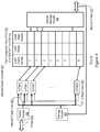
- I/O controller 220 includes packet decoder 222 , which is coupled to I/O bus 214 and ISC 224 .
- ISC 224 includes a message decoder 1404 (that is used to decode conventional EOI messages 306 and escalate messages 1204 received via memory I/O bus 210 ), EAT 226 , and an interrupt message encoder 1406 that utilizes appropriate information in EAT 226 to generate ERMs 1206 for a notification source.
- Packet decoder 222 is configured to decode packets received via I/O bus 214 and select a finite state machine (FSM) to process the received packet based on an event source number for a notification source of the packet.
- FSM finite state machine
- ISC 224 includes an FSM for each row (i.e., S-FSM 0 through S-FSM N) in EAT 226 that is configured to maintain information in EAT 226 to facilitate building ERMs 1206 .
- a different set of FSMs (not shown) is implemented to handle the generation of ERMs 1206 in response to escalate messages 1204 .
- the event source number illustrated in EAT 226 is not a field, but is only used to indicate a row number. For example, source number ‘0’ is assigned to row number ‘0’ of EAT 226 , source number ‘1’ is assigned to row number ‘1’ of EAT 226 , etc.
- each row has an associated ‘event path number’ field, whose values may be utilized to populate corresponding fields in an ERM 1206 , which is generated by interrupt message encoder 1406 when an interrupt is requested by an associated I/O device.
- IRC 260 includes a message decoder 1464 , a message encoder 1468 , and an interrupt routing finite state machine (FSM) 1466 , all of which are coupled to memory I/O bus 210 .
- Message encoder 1468 includes a scope selector 1469 that is configured to determine a scope (e.g., processing unit level, processing node level, or system level) for an ENM 1202 based on values in an associated column of a scope selector table (SST) 1471 (see FIG. 14E ) of scope selector 1469 .
- a scope e.g., processing unit level, processing node level, or system level
- Message decoder 1464 decodes ERMs 1406 received via memory I/O bus 210 .
- An output of message decoder 1464 is coupled to an input of selector 1462 and an input of FSM 1466 .
- IRC 260 also includes an event notification descriptor table (ENDT) 1460 that is coupled to selector 1462 and FSM 1466 .
- Selector 1462 selects an appropriate row in ENDT 1460 responsive to output from message decoder 1464 .
- FSM 1466 which is coupled to message encoder 1468 , provides information selected from ENDT 1460 to message encoder 1468 to facilitate the generation of ENMs 1202 at a scope determined by scope selector 1469 . While SST 1471 is illustrated as being included within scope selector 1469 it should be appreciated that SST 1471 may be located at any location that is accessible to scope selector 1469 .
- each row in ENDT 1460 corresponds to an event path number.
- event path number ‘0’ is assigned to row number ‘0’ of ENDT 1460
- event path number ‘1’ is assigned to row number ‘1’ of ENDT 1460
- each row has an associated address (‘Addr’) field, a generation (‘Gen’) field, an offset counter (‘Offset Ctr’) field, a ‘size’ field, an ‘event priority’ field, an ‘event target number’ field, a ‘number of bits to ignore’ field, a ‘level’ field, a ‘process ID’ field, and an ‘escalate event number’ field.
- Values in fields of ENDT 1460 may be utilized to populate corresponding fields in an ENM 1202 , which is generated by message encoder 1468 responsive to an ERM 1406 when an interrupt is requested by an associated I/O device. Values in the ‘Addr’ field, the ‘Gen’ field, the ‘Offset Ctr’ field, and the ‘size’ field of ENDT 1460 are used to insert information into associated interrupt destination buffers (IDBs).
- IDBs interrupt destination buffers
- an exemplary operating system (OS) image IDB memory structure 1470 includes a virtual processor thread (VPT) list of IDB chains 1472 (i.e., per VPT on a priority basis). Elements (or entries) of IDB chains 1472 include a pointer for each priority level of each VPT that points to a respective VPT IDB header 1474 that is linked, via a link field, to an intermediate logical server IDB header 1476 , which is further linked to a global logical server IDB header 1478 according to one embodiment of the present disclosure.
- Memory structure 1470 also includes an OS image interrupt notification path list 1479 that maintains IDB header pointers with associated priorities for each event path number.
- a block diagram 1480 further illustrates how a specific VPT IDB 1482 is linked to another IDB 1488 via a link field in specific VPT IDB header 1474 a.
- specific VPT IDB 1482 is linked to IDB 1488 via a pointer (link) in specific VPT IDB header 1474 a that points to IDB header 1476 a.
- Information in VPT IDB header 1474 a is used to retrieve information from specific VPT IDB 1482 .
- VPT IDB header 1474 a includes an ‘address’ field that indicates an address of specific VPT IDB 1482 , a generation ‘G’ field that provides a single bit that indicates whether a circular buffer that is formed from specific VPT IDB 1482 has been completely traversed (i.e., has wrapped), a ‘size’ field that indicates a size of specific VPT IDB 1482 , and an ‘offset count’ field that indicates what location in specific VPT IDB 1482 is currently being accessed.
- each element (or entry) in specific VPT IDB 1482 includes a generation ‘G’ field and an ‘event source number’ field. It should be appreciated that multiple different event source numbers may be associated with a single event path number.
- information in IDB header 1476 a is used to retrieve information from IDB 1488 , which may, for example, correspond to a group IDB.
- scope selector 1469 is further illustrated as including a scope selector table (SST) 1471 .
- SST 1471 includes a row for each IPC 240 in data processing system 100 and a column for each event target group (ETG) implemented in data processing system 100 .
- ESG event target group
- SST 1471 may have sixteen rows and sixteen columns.
- ESG event target group
- Broadcasting changes in SST 1471 throughout data processing system 100 ensures that ENMs 1202 are issued by each IRC 260 at an appropriate scope, which may reduce traffic on interconnects 114 and 110 .
- IPC 240 includes a message decoder 1502 , a memory mapped I/O (MMIO) unit 1504 , and a message encoder 1506 all of which are coupled to memory I/O bus 210 .
- Processor cores 200 communicate with IPC 240 via MMIO unit 1504 , using MMIO loads and MMIO stores.
- IPC 240 generates messages (e.g., for ISC 224 and for other IPCs 240 in system 100 ) via message encoder 1506 .
- IPC 240 also includes an ETG counters unit 1505 that is coupled to the ‘valid’ and ‘VP #’ fields of ICT 242 .
- a counter for an associated ETG is incremented when a valid bit is asserted for the ETG and is decremented when the valid bit is deasserted for the ETG.
- ETG counters unit 1505 generates an ENSM trigger 1510 to message encoder 1506 to trigger issuance of an ENSM 1208 .
- Each IPC 240 is configured to issue ENSMs 1208 system wide to notify other IPCs 240 of changes in associated ETGs to enable each IPC 240 in system 100 to track ETGs for all other IPCs 240 in their local SST 1471 .
- IPC 240 receives messages from IRC 260 via message decoder 1502 .
- Message decoder 1502 is coupled to selector 1508 , which is configured to select an FSM (i.e., one of P-FSM 1 through P-FSM M) for message processing based on an event path number associated with a received ENM 1202 .
- FSMs of IPC 240 access interrupt context table (ICT) 242 to initiate generation of an exception to a physical thread executing on a processor core 200 and to generate a trigger escalate message 1509 to message encoder 1506 , which generates an escalate message 1204 in response to trigger escalate message 1509 .
- ICT interrupt context table
- ICT 242 the physical processor thread number illustrated in ICT 242 is not a field, but is only used to indicate a row. For example, physical (processor) thread number ‘0’ is assigned to row number ‘0’ of ICT 242 , physical thread number ‘1’ is assigned to row number ‘1’ of ICT 242 , etc.
- each row is illustrated as having an associated ‘valid’ field, virtual processor number (‘VP #’) field, ‘process ID’ field (used for user level interrupts), an ‘operating priority’ field, an interrupt acknowledge count (‘IAC’) field, an ‘escalate event number’ field, an ‘assigned’ field, an ‘event path number’ field, an ‘event priority’ field, and a ‘preferred’ field, at least some of whose values may be retrieved by a processor core using a MMIO load in response to an exception line being asserted by IPC 240 .
- ‘VP #’ virtual processor number
- processor ID used for user level interrupts
- IAC interrupt acknowledge count
- the ‘valid’ field indicates whether a processor is installed and powered on and whether a VP is dispatched and operating on an associated physical processor thread.
- the ‘VP #’ field specifies a number of the VP that is dispatched on the associated physical processor thread, as well as an associated ETG. In one embodiment, the lower four bits of the ‘VP #’ field specify the VP number and the upper four bits of the ‘VP #’ field specify the ETG.
- the ‘process ID’ field specifies a process ID for a user level interrupt.
- the ‘operating priority’ field specifies a priority level of a program currently running on the associated physical processor thread.
- the ‘IAC’ field specifies a current IAC that is used to determine whether an associated VP thread has been interrupted too often.
- the IAC is decremented when the associated VP thread is interrupted and may be periodically incremented while the associated VP thread is dispatched to implement a rate instrument.
- the ‘escalate event number’ field (which may, for example, be setup by OS or hypervisor software) specifies an event source number that is used to escalate an interrupt to a higher software level when a VP thread associated with a current software stack level is interrupted too frequently. It should be appreciated that additional similar VP threads may also be dispatched to service a workload when a given VP thread is interrupted too frequently.
- the ‘preferred’ field may be utilized by software to indicate a preferred VP thread to interrupt.
- ICT 242 is further illustrated as including three different ICTs (i.e., a hypervisor stack level ICT 242 a, an OS stack level ICT 242 b, and a user stack level ICT 242 c ), each of which has different associated exception lines 212 a, 212 b, and 212 c routed to processor cores 200 .
- ICT 242 c includes a ‘process ID’ field.
- selector 1508 include comparators (CMP 0 through CMP M), i.e., one for each row in ICT 242 , that compare an ‘event target number’, a ‘process ID’ for user level interrupts, a ‘level’, and ‘number of bits to ignore’ provided in ENM 1202 and ‘valid’, ‘process ID’ for user level interrupts, and ‘VP #’ values stored in respective rows of an appropriate one of ICTs 242 a, 242 b, or 242 c.
- comparators CMP 0 through CMP M
- Outputs of the comparators are provided to a ‘no hits’ unit 1652 which determines whether any VP threads are available to be interrupted (when the interrupt is a user level interrupt the process IDs are also compared). In the event zero VP threads are available to be interrupted, ‘no hits’ unit 1652 issues trigger escalate message 1509 ) to message encoder 1506 (see FIG. 15A ). In the event more than one VP thread is available to be interrupted, ‘secondary selection’ unit 1654 determines which VP thread should be interrupted and issues an appropriate interrupt trigger to trigger an interrupt on an associated physical processor thread.
- ‘Secondary selection’ unit 1654 may implement various secondary selection criteria in determining which available VP thread to select for interruption. For example, ‘secondary selection’ unit 1654 may select a VP thread to interrupt based on ‘event priority’ relative to ‘operating priority’, least recently used (LRU), and/or random, etc. According to one aspect of the present disclosure, ‘preferred’ bits 1511 from appropriate rows (sourced from a ‘preferred’ field of ICT 242 ) are utilized by secondary selection unit 1654 in determining which of one of multiple VP threads is selected to be interrupted to service the interrupt. It should be appreciated that the various selection criteria may be implemented in series to select a single VP thread when multiple VP threads are still available after a given selection process.
- IPC 240 issues escalate message 1204 to ISC 224 using an appropriate row of ICT 242 as a source for the escalate event number.
- Process 1600 may, for example, be initiated in block 1602 when ISC 224 receives input via I/O bus 214 or via memory I/O bus 210 .
- ISC 224 determines whether the received input corresponds to an interrupt trigger (or interrupt trigger pulse) or an escalate message 1204 .
- ISC 224 determines whether the received input corresponds to an interrupt trigger (or interrupt trigger pulse) or an escalate message 1204 .
- control loops on block 1604 .
- control transfers to block 1606 .
- ISC 224 builds an ERM 1206 based on associated information in EAT 226 . It should be appreciated that when the received input is an escalate message 1204 with an associated escalate event number, the escalate event number is utilized as the event source number in building a new ERM 1206 .
- ISC 224 issues ERM 1206 to IRC 260 via memory I/O bus 210 .
- ISC 224 determines whether an EOI message 306 has been received from IPC 240 . In response to ISC 224 not receiving an EOI message 306 in block 1612 control loops on block 1612 . In response to ISC 224 receiving an EOI message 306 in block 1612 control returns to block 1604 .
- Process 1650 is illustrated that is implemented by IRC 260 to handle interrupts.
- Process 1650 may, for example, be initiated in block 1652 when IRC 260 receives input via memory I/O bus 210 .
- IRC 260 determines whether the received input corresponds to an event routing message (ERM) 1206 .
- ERM event routing message
- control loops on block 1654 .
- ERM 1206 control transfers to block 1656 .
- IRC 260 selects a row in event notification descriptor table (ENDT) 1460 per a value of the ‘event path number’ field of ERM 1206 .
- ERM event routing message
- IRC 260 stores a generation bit and event source number (from ENDT 1460 ) in an interrupt destination buffer (IDB) associated with the event path number (i.e., at an address and offset count specified by the address ‘Addr’ field and offset counter ‘Offset Ctr’ field of ENDT 1460 ).
- IDBs may be allocated in main memory or another memory associated with IRC 260 .
- the generation bit is used to track whether an associated IDB, which in one embodiment is implemented as a circular buffer, has been completely traversed.
- IRC 260 increments the offset counter for the IDB modulo the length of the IDB (size field of ENDT 1460 ), i.e., to point to a next entry in the IDB, in ENDT 1460 .
- decision block 1662 IRC 260 determines whether the offset counter has wrapped. In response to the offset counter wrapping in block 1662 control transfers to block 1664 .
- IRC 260 changes the polarity of the IDB generation bit in ENDT 1460 .
- IRC 260 builds an event notification message (ENM) 1202 based on associated information in ENDT 1460 .
- IRC 260 determines an ETG for ENM 1202 using an ETG portion of the VP # field and determines a scope for ENM 1202 based on entries in an ETG appropriate column of SST 1471 .
- control transfers to block 1668 where IRC 260 issues ENM 1202 to one or more IPCs 240 at a scope determined by scope selector 1469 .
- scope selector 1469 accesses a column in SST 1471 for the ETG specified in ENM 1202 and then utilizes the smallest scope necessary to reach all IPCs 240 that are indicated to have at least one valid VP for the ETG. If the ETG is only valid for an associated IPC 240 , ENM 1202 is only issued at a chip scope (i.e., a processing unit 104 level).
- ENM 1202 is issued at a processing node scope (i.e., at a processing node 102 level). Finally, if the ETG is valid for at least one IPC 240 outside of an associated processing node, ENM 1202 is transmitted at a system scope (i.e., to all processing nodes 102 within data processing system 100 ). Next, control transfers from block 1668 to block 1654 .
- IPC 240 handles event notification messages differently from how IPC 540 handles event notification messages (see FIG. 7 ).
- Process 1700 is initiated in block 1701 when IPC 240 receives input via memory I/O bus 210 .
- IPC 240 determines whether an ENM 1202 was received. It should be appreciated that ISC 224 operates differently from ISC 424 (see FIG.
- ISC 224 builds ERMs 1206 (as contrasted with ENMs 302 ) that are sent to IRC 260
- IRC 260 builds an ENM 1202 (responsive to an ERM 1206 ) that is sent to IPC 240 .
- ENM 1202 includes an additional ‘process ID’ field, an additional ‘level’ field, an additional ‘number of bits to ignore’ field, an ‘escalate event number’ field, an ‘event path number’ field replaces the ‘event source number’ field, and the ‘event target number’ field provides a virtual processor thread number instead of a physical processor thread number.
- control transfers to block 1703 .
- IPC 240 compares the ‘event target number’ from ENM 1202 with all valid VP numbers, ignoring the number of lower-order bits specified (in the ‘number of bits to ignore’ field) by ENM 1202 .
- IPC 240 determines whether the ‘level’ field indicates that the interrupt is a user level interrupt. In response to the interrupt being a user level interrupt control transfers from block 1704 to block 1706 .
- IPC 240 compares the ‘process ID’ of ENM 1202 with ‘process IDs’ of rows in ICT 242 c with matching valid VP numbers. From block 1706 control transfers to decision block 1708 . In response to the interrupt not being a user level interrupt in block 1704 control transfers directly to block 1708 .
- IPC 240 determines whether a hit occurred for at least one VP thread.
- no hits i.e., no VP threads being available to be interrupted due to no VP thread being valid that meets the VP selection criteria (i.e., specified in the ‘event target number’ field and the ‘number of bits to ignore’ field) with the specified process ID for a user level interrupt
- control transfers to block 1709 where IPC 240 issues an escalate message 1204 (to escalate the interrupt to a next higher software stack level, assuming a higher level is available) with an associated escalate event number (EEN), sourced by IRC 260 in ENM 1202 . From block 1709 control returns to block 1702 .
- escalate message 1204 to escalate the interrupt to a next higher software stack level, assuming a higher level is available
- EEN escalate event number
- IPC 240 In response to IPC 240 determining that there is at least one hit that does not already have a pending interrupt assigned in block 1712 control transfers to block 1716 .
- IPC 240 selects (e.g., based on ‘preferred’ bits 1511 from appropriate rows (sourced from a ‘preferred’ field of ICT 242 ) and may also utilize event priority' relative to ‘operating priority’, least recently used (LRU), and/or random, etc. in the event that multiple ‘preferred’ bits 1511 are asserted) a row in ICT 242 to trigger an interrupt.
- LRU least recently used
- IPC 240 asserts an ‘assigned’ field (to indicate an interrupt is pending), and sets an ‘event path number’ field and an ‘event priority’ field of the selected row per ENM 1202 .
- control returns to block 1702 .
- IPC 240 determines whether an interrupt priority (i.e., the event priority) of ENM 1202 is greater than an operating priority of any row with a hit that has a pending interrupt.
- IPC 240 selects (e.g., based on ‘preferred’ bits 1511 from appropriate rows (sourced from a ‘preferred’ field of ICT 242 ) and may also utilize event priority' relative to ‘operating priority’, least recently used (LRU), and/or random, etc. in the event that multiple ‘preferred’ bits 1511 are asserted) a row in ICT 242 to trigger an interrupt. From block 1720 control transfers to block 1718 and then to block 1702 .
- LRU least recently used
- Process 1750 is illustrated that is implemented (for example, by executing a software routine) by a processor core 200 to handle interrupts.
- Process 1750 is initiated in block 1752 in response to IPC 240 signaling an interrupt (i.e., an event priority of an interrupt being higher than an operating priority of a VPT that is interrupted).
- processor core 200 issues a MMIO load to an interrupt acknowledge address for IPC 240 and receives, in response to the MMIO load, an event path number.
- processor core 200 uses the event path number to index a per OS image interrupt notification path list 1479 (see FIG.
- processor core 200 sets a scan priority to a priority associated with the event path number in list 1479 .
- processor core 200 sets an operating priority of the row to one level less than the scan priority.
- processor core 200 uses the scan priority to index a VP list of interrupt destination buffer (IDB) chains 1472 to retrieve a first IDB (e.g., IDB 1482 ) in the VP list of IDB chains 1472 .
- processor core 200 executes a program registered to handle the event source number and, upon completion of the registered program, then issues a MMIO store to IPC 240 to signal an EOI.
- IDB interrupt destination buffer
- processor core 200 determines whether there is another IDB in the IDB chain.
- control transfers to block 1766 , where processor core 200 links to the next IDB in the IDB chain.
- processor core 200 may access IDB header 1474 a for a link to IDB header 1476 a, which provides an address of a first element in IDB 1488 .
- From block 1766 control returns to block 1762 .
- decision block 1768 processor core 200 determines whether there is another interrupt pending in IPC 240 .
- control In response to another interrupt being pending in block 1768 control returns to block 1754 . In response to another interrupt not being pending in block 1768 control transfers to block 1770 . In block 1770 processor core 200 sets the scan priority to the next less favored priority level.
- processor core 200 determines whether the scan priority is greater than the pre-interrupt operating priority. In response to the scan priority level being greater than the pre-interrupt operating priority level in block 1772 control returns to block 1758 . In response to the scan priority level not being greater than the pre-interrupt operating priority level in block 1772 control transfers to block 1774 . In block 1774 processor core 200 sets the operating priority of the row to the pre-interrupt value.
- processor core 200 returns to a suspended program that was interrupted.
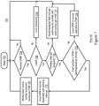
- an exemplary process 1800 is illustrated that is implemented by IPC 240 to handle certain MMIO stores received from a processor core.
- a processor core 200 may issue a MMIO store to IPC 240 to invalidate all associated VPs.
- Process 1800 is initiated in block 1802 when, for example, IPC 240 receives a MMIO store from a given processor core 200 .
- decision block 1804 IPC 240 determines whether the MMIO store is directed to deasserting (resetting) a valid bit in one or more rows in ICT 242 .
- control loops on block 1804 In response to the received MMIO store not being directed to deasserting a valid bit in one or more rows in ICT 242 control loops on block 1804 .
- IPC 240 deasserts the valid bit for the row or rows.
- IPC 240 decrements the ETG count for the row or rows. Following block 1808 control returns to block 1804 .
- IPC 240 may issue a MMIO store to IPC 240 to validate all associated VPs.
- Process 1810 is initiated in block 1812 when, for example, IPC 240 receives a MMIO store from a given processor core 200 .
- decision block 1814 IPC 240 determines whether the MMIO store is directed to asserting (setting) a valid bit in one or more rows in ICT 242 .
- control loops on block 1814 In response to the received MMIO store not being directed to asserting a valid bit in one or more rows in ICT 242 control loops on block 1814 .
- IPC 240 asserts the valid bit for the row or rows.
- IPC 240 increments the ETG count for the row or rows. Following block 1818 control returns to block 1814 .
- an exemplary process 1820 is illustrated that is implemented by IPC 240 to handle a received ENSM 1208 .
- an IPC 240 may broadcast an ENSM 1208 to all other IPCs 240 in response to a local change in SST 1471 .
- Process 1820 may be initiated in block 1822 when, for example, IPC 240 receives a communication.
- decision block 1824 IPC 240 determines whether the communication is an ENSM 1208 .
- control loops on block 1824 .
- control transfers from block 1824 to block 1826 .
- IPC 240 updates the ETG vector in SST 1471 for the IPC ID indicated in ENSM 1208 .
- control returns to block 1824 .
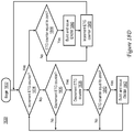
- an exemplary process 1830 is illustrated that is implemented by IPC 240 in response to determining a change in a valid bit in a row of ICT 242 is indicated.
- the process 1830 is initiated in block 1832 in response to IPC 240 receiving a MIMO store from a processor core 200 to change a valid bit in a row in ICT 242 .
- IPC 240 determines whether an associated ETG counter should be incremented (i.e., whether the valid bit for the row is being asserted for the ETG specified by the VP # field of the row).
- IPC 240 determines whether the ETG counter is equal to zero. In response to the ETG counter being equal to zero control transfers from block 1844 to block 1846 , where IPC 240 builds and issues an ENSM 1208 at a system level, i.e., to all other IPCs 240 in data processing system 100 .
- IPC 240 increments the ETG counter. In response to the ETG counter not being equal to zero control transfers directly from block 1844 to block 1848 . Following block 1848 control returns to block 1834 . In response to IPC 240 determining that the ETG counter should not be incremented in block 1834 control transfers to decision block 1836 . In block 1836 IPC 240 determines whether the ETG counter should be decremented (i.e., whether the valid bit for the row is being deasserted for the ETG specified by the VP # field of the row). In response to determining that the ETG counter should not be decremented in block 1836 control transfers to block 1834 .
- IPC 240 determines whether the ETG counter is equal to zero. In response to the ETG counter not being equal to zero control transfers from block 1840 to block 1834 . In response to the ETG counter being equal to zero control transfers from block 1840 to block 1842 , where IPC 240 builds and issues an ENSM 1208 at a system level, i.e., to all other IPCs 240 in data processing system 100 . Following block 1842 control returns to block 1834 .
- Process 1900 may be periodically executed by IPC 240 to determine whether IPC 240 has received a communication (e.g., a MMIO load or a MMIO store) from a processor core with respect to a pending interrupt.
- a communication e.g., a MMIO load or a MMIO store
- Process 1900 is initiated in block 1902 at which point control transfers to decision block 1904 .
- IPC 240 determines whether a MMIO load has been received at an interrupt acknowledge address. In response to a MMIO load not being received at the interrupt acknowledge address control loops on block 1904 .
- IPC 240 In response to a MMIO load being received at the interrupt acknowledge address control transfers from block 1904 to block 1906 .
- IPC 240 atomically sets an operating priority of the acknowledged interrupt to the pending interrupt event priority and deasserts (resets) the assigned field for the interrupt in ICT 242 , and returns the pending interrupt event path number as response data to the MMIO load.
- IPC 240 decrements an interrupt acknowledge count (IAC).
- IAC interrupt acknowledge count
- the ‘IAC’ field specifies a current IAC that is used to determine whether an associated VP thread has been interrupted too often.
- the IAC is decremented when the associated VP thread is interrupted and may be periodically incremented while the associated VP thread is dispatched to implement a rate instrument.
- IPC 240 determines whether the IAC is equal to zero (or alternatively some other threshold level). In response to the IAC not being equal to zero control transfers from block 1910 to block 1904 . In response to the IAC being equal to zero control transfers from block 1910 to block 1912 .
- IPC 240 sends an escalate message to ISC 224 per the escalate event number of the row of ICT 242 that is being acknowledged to provide relief for the VPT that has been interrupted too often. From block 1912 control returns to block 1904 . While process 1900 is described as being implemented using a count-down approach, it should be appreciated that a similar process may be implemented using a count-up approach. It should also be appreciated that the threshold level and/or the IAC may be periodically modified to implement a rate instrument. As one example, the IAC may be periodically incremented and the threshold level may be maintained at a fixed value to implement a rate instrument.
- Process 2000 is initiated in block 2002 in response to, for example, processor core 200 determining that a virtual processor thread (VPT) is to be preempted, e.g., such that a higher priority interrupt can be serviced, and that a state of the preempted VPT should be saved.
- processor core 200 deasserts (resets) an exception enable bit (e.g., maintained in an internal processor register).
- an exception enable bit e.g., maintained in an internal processor register.
- processor core 200 masks interrupts by deasserting an associated exception enable bit.
- processor core 200 saves architected processor registers in a VP context save area in memory (e.g., system memory 108 ). Then, in block 2008 , processor core 200 issues a MMIO store to IPC 240 to deassert (reset) the VP valid bit. Next, in block 2010 , processor core 200 issues one or more MMIO loads to save an entry in ICT 242 in association with the architected processor registers in the VP context save area in memory. Then, control transfers to block 2012 where process 2000 terminates.
- memory e.g., system memory 108
- processor core 200 issues a MMIO store to IPC 240 to deassert (reset) the VP valid bit.
- processor core 200 issues one or more MMIO loads to save an entry in ICT 242 in association with the architected processor registers in the VP context save area in memory. Then, control transfers to block 2012 where process 2000 terminates.
- Process 2100 is illustrated that is implemented by a processor core, configured according to the present disclosure, to handle interrupts.
- Process 2100 is initiated in block 2102 in response to, for example, processor core 200 determining that a new virtual processor thread (VPT) requires dispatching.
- processor core 200 deasserts (resets) an associated exception enable bit (e.g., maintained in an internal processor register). It should be appreciated that processor core 200 masks interrupts by deasserting the exception enable bit.
- VPT virtual processor thread
- processor core 200 uses one or more MMIO stores to restore an associated entry in ICT 242 from a VP context save area in memory (e.g., system memory 108 ) and sets a pending interrupt to the most favored VPT interrupt path. Then, in block 2108 , processor core 200 issues a MMIO store to assert (set) the VP valid bit in an appropriate entry in IPC 240 .
- processor core 200 issues one or more MMIO stores to restore the architected processor registers from the VP context save area in memory. Then, in block 2112 processor core 200 atomically asserts (sets) the exception enable bit and returns control flow to the interrupted program. Control then transfers from block 2112 to block 2114 where process 2100 terminates.
- Process 2200 is initiated in block 2202 , for example, in response to a lowering in operating priority being indicated. For example, when an operating priority is lowered there may be a pending interrupt that now has a higher event priority (than the lowered operating priority) that should be serviced.
- processor core 200 sets a scan priority to a current operating priority.
- processor core 200 sets the operating priority in an associated row to one level less than the scan priority.
- processor core 200 uses the scan priority to index VP list of IDB chains 1472 to retrieve a first IDB in the IDB chain.
- for each unprocessed element in the IDB processor core 200 executes the program registered to handle the event source number and issues a MMIO store to IPC 240 to signal an EOI.
- processor core 200 determines whether there is another IDB in the IDB chain. In response to there being another IDB in the IDB chain in block 2212 control transfers to block 2214 , where processor core 200 links to the next IDB in the IDB chain. From block 2214 control returns to block 2210 . In response to there not being another IDB in the IDB chain in block 2212 control transfers to decision block 2216 , where processor core 200 determines whether there is another interrupt pending in IPC 240 . In response to another interrupt being pending in block 2216 control transfers to block 2226 , where processor core 200 acknowledges the pending interrupt by issuing a MMIO load to an acknowledge address for IPC 240 and receives an event path number in response. Next, in block 2228 , processor core 200 uses the event path number associated with the pending interrupt to index OS image interrupt notification path list 1479 and sets a scan priority to the associated priority. Following block 2228 control returns to block 2206 .
- processor core 200 sets the scan priority to the next less favored priority level.
- decision block 2220 processor core 200 determines whether the scan priority is greater than the pre-interrupt operating priority. In response to the scan priority level being greater than the pre-interrupt operating priority level in block 2220 control returns to block 2208 . In response to the scan priority level not being greater than the pre-interrupt operating priority level in block 2220 control transfers to block 2222 . In block 2222 processor core 200 sets operating priority of the row to the pre-interrupt value. Next, in block 2224 , processor core 200 returns to a suspended program that was interrupted.
- Process 2300 is initiated in block 2302 when, for example, IPC 240 receives a MMIO operation from a given processor core 200 .
- IPC 240 determines whether a MMIO store has been received at an operating priority address. In response to not receiving a MMIO at the operating priority address control loops on block 2304 . In response to the receiving MMIO store at the operating priority address control transfers from block 2304 to block 2306 .
- IPC 240 sets the operating priority per data associated with the MMIO store. Following block 2306 control returns to block 2304 .
- IDBs interrupt destination buffers
- NRMs reject messages
- the methods depicted in the figures may be embodied in a computer-readable medium as one or more design files.
- certain steps of the methods may be combined, performed simultaneously or in a different order, or perhaps omitted, without deviating from the spirit and scope of the invention.
- the method steps are described and illustrated in a particular sequence, use of a specific sequence of steps is not meant to imply any limitations on the invention. Changes may be made with regards to the sequence of steps without departing from the spirit or scope of the present invention. Use of a particular sequence is therefore, not to be taken in a limiting sense, and the scope of the present invention is defined only by the appended claims.
- aspects of the present invention may be embodied as a system, method or computer program product. Accordingly, aspects of the present invention may take the form of an entirely hardware embodiment or an embodiment combining software and hardware aspects that may all generally be referred to herein as a “circuit,” “module” or “system.”
- the computer-readable medium may be a computer-readable signal medium or a computer-readable storage medium.
- a computer-readable storage medium may be, for example, but not limited to, an electronic, magnetic, optical, electromagnetic, infrared, or semiconductor system, apparatus, or device, or any suitable combination of the foregoing, but does not include a computer-readable signal medium.
- a computer-readable storage medium may be any tangible storage medium that can contain, or store a program for use by or in connection with an instruction execution system, apparatus, or device.
Landscapes
- Engineering & Computer Science (AREA)
- Theoretical Computer Science (AREA)
- Physics & Mathematics (AREA)
- General Engineering & Computer Science (AREA)
- General Physics & Mathematics (AREA)
- Bus Control (AREA)
Abstract
Description
Claims (6)
Priority Applications (1)
| Application Number | Priority Date | Filing Date | Title |
|---|---|---|---|
| US15/826,212 US10565140B2 (en) | 2017-06-06 | 2017-11-29 | Techniques for issuing interrupts in a data processing system with multiple scopes |
Applications Claiming Priority (2)
| Application Number | Priority Date | Filing Date | Title |
|---|---|---|---|
| US15/615,338 US10210112B2 (en) | 2017-06-06 | 2017-06-06 | Techniques for issuing interrupts in a data processing system with multiple scopes |
| US15/826,212 US10565140B2 (en) | 2017-06-06 | 2017-11-29 | Techniques for issuing interrupts in a data processing system with multiple scopes |
Related Parent Applications (1)
| Application Number | Title | Priority Date | Filing Date |
|---|---|---|---|
| US15/615,338 Continuation US10210112B2 (en) | 2017-06-06 | 2017-06-06 | Techniques for issuing interrupts in a data processing system with multiple scopes |
Publications (2)
| Publication Number | Publication Date |
|---|---|
| US20180349307A1 US20180349307A1 (en) | 2018-12-06 |
| US10565140B2 true US10565140B2 (en) | 2020-02-18 |
Family
ID=64459709
Family Applications (3)
| Application Number | Title | Priority Date | Filing Date |
|---|---|---|---|
| US15/615,338 Expired - Fee Related US10210112B2 (en) | 2017-06-06 | 2017-06-06 | Techniques for issuing interrupts in a data processing system with multiple scopes |
| US15/826,212 Expired - Fee Related US10565140B2 (en) | 2017-06-06 | 2017-11-29 | Techniques for issuing interrupts in a data processing system with multiple scopes |
| US16/254,239 Expired - Fee Related US10552351B2 (en) | 2017-06-06 | 2019-01-22 | Techniques for issuing interrupts in a data processing system with multiple scopes |
Family Applications Before (1)
| Application Number | Title | Priority Date | Filing Date |
|---|---|---|---|
| US15/615,338 Expired - Fee Related US10210112B2 (en) | 2017-06-06 | 2017-06-06 | Techniques for issuing interrupts in a data processing system with multiple scopes |
Family Applications After (1)
| Application Number | Title | Priority Date | Filing Date |
|---|---|---|---|
| US16/254,239 Expired - Fee Related US10552351B2 (en) | 2017-06-06 | 2019-01-22 | Techniques for issuing interrupts in a data processing system with multiple scopes |
Country Status (1)
| Country | Link |
|---|---|
| US (3) | US10210112B2 (en) |
Families Citing this family (12)
| Publication number | Priority date | Publication date | Assignee | Title |
|---|---|---|---|---|
| TWI764082B (en) | 2019-02-14 | 2022-05-11 | 美商萬國商業機器公司 | Method, computer system and computer program product for interrupt signaling for directed interrupt virtualization |
| CN113454590B (en) | 2019-02-14 | 2025-05-30 | 国际商业机器公司 | Directed Interrupt Virtualization |
| TWI759677B (en) | 2019-02-14 | 2022-04-01 | 美商萬國商業機器公司 | Method, computer system and computer program product for directed interrupt virtualization with fallback |
| TWI727607B (en) | 2019-02-14 | 2021-05-11 | 美商萬國商業機器公司 | Method, computer system and computer program product for directed interrupt virtualization with interrupt table |
| WO2020164819A1 (en) | 2019-02-14 | 2020-08-20 | International Business Machines Corporation | Directed interrupt for multilevel virtualization with interrupt table |
| WO2020164818A1 (en) | 2019-02-14 | 2020-08-20 | International Business Machines Corporation | Directed interrupt for multilevel virtualization |
| EP3924821B1 (en) | 2019-02-14 | 2025-01-01 | International Business Machines Corporation | Directed interrupt virtualization with running indicator |
| US11513983B2 (en) * | 2020-05-15 | 2022-11-29 | International Business Machines Corporation | Interrupt migration |
| US11561819B2 (en) | 2021-06-11 | 2023-01-24 | International Business Machines Corporation | Techniques for adapting escalation paths of interrupts in a data processing system |
| US12020066B2 (en) | 2021-06-11 | 2024-06-25 | International Busin ess Machines Corporation | Asynchronous completion notification in a multi-core data processing system |
| US11755362B2 (en) | 2021-06-11 | 2023-09-12 | International Business Machines Corporation | Techniques for handling escalation of interrupts in a data processing system |
| GB202202819D0 (en) | 2022-03-01 | 2022-04-13 | Graphcore Ltd | Global event aggregation |
Citations (8)
| Publication number | Priority date | Publication date | Assignee | Title |
|---|---|---|---|---|
| US5701495A (en) | 1993-09-20 | 1997-12-23 | International Business Machines Corporation | Scalable system interrupt structure for a multi-processing system |
| US6430643B1 (en) | 1999-09-02 | 2002-08-06 | International Business Machines Corporation | Method and system for assigning interrupts among multiple interrupt presentation controllers |
| US20060010277A1 (en) | 2004-07-08 | 2006-01-12 | International Business Machines Corporation | Isolation of input/output adapter interrupt domains |
| US7003611B2 (en) | 2003-09-30 | 2006-02-21 | International Business Machines Corporation | Method and apparatus for handling interrupts using a set of interrupts servers associated with presentation controllers |
| US20080109564A1 (en) * | 2006-11-03 | 2008-05-08 | Arndt Richard L | Method, system, and apparatus for enhanced management of message signaled interrupts |
| US7653912B2 (en) | 2003-05-30 | 2010-01-26 | Steven Frank | Virtual processor methods and apparatus with unified event notification and consumer-producer memory operations |
| US7907623B2 (en) * | 2006-02-14 | 2011-03-15 | Robert Bosch Gmbh | Gateway for automatically routing messages between buses |
| US8510599B2 (en) | 2010-06-23 | 2013-08-13 | International Business Machines Corporation | Managing processing associated with hardware events |
-
2017
- 2017-06-06 US US15/615,338 patent/US10210112B2/en not_active Expired - Fee Related
- 2017-11-29 US US15/826,212 patent/US10565140B2/en not_active Expired - Fee Related
-
2019
- 2019-01-22 US US16/254,239 patent/US10552351B2/en not_active Expired - Fee Related
Patent Citations (8)
| Publication number | Priority date | Publication date | Assignee | Title |
|---|---|---|---|---|
| US5701495A (en) | 1993-09-20 | 1997-12-23 | International Business Machines Corporation | Scalable system interrupt structure for a multi-processing system |
| US6430643B1 (en) | 1999-09-02 | 2002-08-06 | International Business Machines Corporation | Method and system for assigning interrupts among multiple interrupt presentation controllers |
| US7653912B2 (en) | 2003-05-30 | 2010-01-26 | Steven Frank | Virtual processor methods and apparatus with unified event notification and consumer-producer memory operations |
| US7003611B2 (en) | 2003-09-30 | 2006-02-21 | International Business Machines Corporation | Method and apparatus for handling interrupts using a set of interrupts servers associated with presentation controllers |
| US20060010277A1 (en) | 2004-07-08 | 2006-01-12 | International Business Machines Corporation | Isolation of input/output adapter interrupt domains |
| US7907623B2 (en) * | 2006-02-14 | 2011-03-15 | Robert Bosch Gmbh | Gateway for automatically routing messages between buses |
| US20080109564A1 (en) * | 2006-11-03 | 2008-05-08 | Arndt Richard L | Method, system, and apparatus for enhanced management of message signaled interrupts |
| US8510599B2 (en) | 2010-06-23 | 2013-08-13 | International Business Machines Corporation | Managing processing associated with hardware events |
Non-Patent Citations (2)
| Title |
|---|
| Auernhammer et al., U.S. Appl. No. 15/615,338, filed Jun. 6, 2017, Notice of Allowance dated Oct. 9, 2018. |
| Auernhammer et al., U.S. Appl. No. 16/254,239, filed Jan. 22, 2019, Notice of Allowance dated Sep. 25, 2019. |
Also Published As
| Publication number | Publication date |
|---|---|
| US20190155771A1 (en) | 2019-05-23 |
| US10552351B2 (en) | 2020-02-04 |
| US20180349305A1 (en) | 2018-12-06 |
| US10210112B2 (en) | 2019-02-19 |
| US20180349307A1 (en) | 2018-12-06 |
Similar Documents
| Publication | Publication Date | Title |
|---|---|---|
| US10552351B2 (en) | Techniques for issuing interrupts in a data processing system with multiple scopes | |
| US9792232B2 (en) | Techniques for queueing interrupts in a data processing system | |
| US9317434B2 (en) | Managing out-of-order memory command execution from multiple queues while maintaining data coherency | |
| US5832304A (en) | Memory queue with adjustable priority and conflict detection | |
| US5640519A (en) | Method and apparatus to improve latency experienced by an agent under a round robin arbitration scheme | |
| US10229074B2 (en) | Techniques for handling interrupts in a processing unit using interrupt request queues | |
| US11755362B2 (en) | Techniques for handling escalation of interrupts in a data processing system | |
| US11561819B2 (en) | Techniques for adapting escalation paths of interrupts in a data processing system |
Legal Events
| Date | Code | Title | Description |
|---|---|---|---|
| AS | Assignment |
Owner name: INTERNATIONAL BUSINESS MACHINES CORPORATION, NEW YORK Free format text: ASSIGNMENT OF ASSIGNORS INTEREST;ASSIGNORS:AUERNHAMMER, FLORIAN A.;BARRETT, WAYNE M.;DREHMEL, ROBERT A.;AND OTHERS;SIGNING DATES FROM 20170605 TO 20170606;REEL/FRAME:044253/0416 Owner name: INTERNATIONAL BUSINESS MACHINES CORPORATION, NEW Y Free format text: ASSIGNMENT OF ASSIGNORS INTEREST;ASSIGNORS:AUERNHAMMER, FLORIAN A.;BARRETT, WAYNE M.;DREHMEL, ROBERT A.;AND OTHERS;SIGNING DATES FROM 20170605 TO 20170606;REEL/FRAME:044253/0416 |
|
| FEPP | Fee payment procedure |
Free format text: ENTITY STATUS SET TO UNDISCOUNTED (ORIGINAL EVENT CODE: BIG.); ENTITY STATUS OF PATENT OWNER: LARGE ENTITY |
|
| STPP | Information on status: patent application and granting procedure in general |
Free format text: RESPONSE TO NON-FINAL OFFICE ACTION ENTERED AND FORWARDED TO EXAMINER |
|
| STPP | Information on status: patent application and granting procedure in general |
Free format text: FINAL REJECTION MAILED |
|
| STPP | Information on status: patent application and granting procedure in general |
Free format text: RESPONSE AFTER FINAL ACTION FORWARDED TO EXAMINER |
|
| STPP | Information on status: patent application and granting procedure in general |
Free format text: NOTICE OF ALLOWANCE MAILED -- APPLICATION RECEIVED IN OFFICE OF PUBLICATIONS |
|
| STPP | Information on status: patent application and granting procedure in general |
Free format text: NOTICE OF ALLOWANCE MAILED -- APPLICATION RECEIVED IN OFFICE OF PUBLICATIONS |
|
| STCF | Information on status: patent grant |
Free format text: PATENTED CASE |
|
| FEPP | Fee payment procedure |
Free format text: MAINTENANCE FEE REMINDER MAILED (ORIGINAL EVENT CODE: REM.); ENTITY STATUS OF PATENT OWNER: LARGE ENTITY |
|
| LAPS | Lapse for failure to pay maintenance fees |
Free format text: PATENT EXPIRED FOR FAILURE TO PAY MAINTENANCE FEES (ORIGINAL EVENT CODE: EXP.); ENTITY STATUS OF PATENT OWNER: LARGE ENTITY |
|
| STCH | Information on status: patent discontinuation |
Free format text: PATENT EXPIRED DUE TO NONPAYMENT OF MAINTENANCE FEES UNDER 37 CFR 1.362 |
|
| FP | Lapsed due to failure to pay maintenance fee |
Effective date: 20240218 |