US1056487A - Carbonating apparatus. - Google Patents
Carbonating apparatus. Download PDFInfo
- Publication number
- US1056487A US1056487A US61455711A US1911614557A US1056487A US 1056487 A US1056487 A US 1056487A US 61455711 A US61455711 A US 61455711A US 1911614557 A US1911614557 A US 1911614557A US 1056487 A US1056487 A US 1056487A
- Authority
- US
- United States
- Prior art keywords
- platform
- tank
- pump
- water
- agitator
- Prior art date
- Legal status (The legal status is an assumption and is not a legal conclusion. Google has not performed a legal analysis and makes no representation as to the accuracy of the status listed.)
- Expired - Lifetime
Links
- XLYOFNOQVPJJNP-UHFFFAOYSA-N water Substances O XLYOFNOQVPJJNP-UHFFFAOYSA-N 0.000 description 16
- 239000007788 liquid Substances 0.000 description 12
- 238000010276 construction Methods 0.000 description 5
- 230000005484 gravity Effects 0.000 description 2
- 238000004519 manufacturing process Methods 0.000 description 2
- CDBYLPFSWZWCQE-UHFFFAOYSA-L Sodium Carbonate Chemical compound [Na+].[Na+].[O-]C([O-])=O CDBYLPFSWZWCQE-UHFFFAOYSA-L 0.000 description 1
- 235000014171 carbonated beverage Nutrition 0.000 description 1
- 239000003814 drug Substances 0.000 description 1
- 229940079593 drug Drugs 0.000 description 1
- 239000011521 glass Substances 0.000 description 1
- 239000000203 mixture Substances 0.000 description 1
- 210000002445 nipple Anatomy 0.000 description 1
- 238000012856 packing Methods 0.000 description 1
- 238000003756 stirring Methods 0.000 description 1
Images

Classifications
-
- B—PERFORMING OPERATIONS; TRANSPORTING
- B01—PHYSICAL OR CHEMICAL PROCESSES OR APPARATUS IN GENERAL
- B01F—MIXING, e.g. DISSOLVING, EMULSIFYING OR DISPERSING
- B01F23/00—Mixing according to the phases to be mixed, e.g. dispersing or emulsifying
- B01F23/20—Mixing gases with liquids
- B01F23/23—Mixing gases with liquids by introducing gases into liquid media, e.g. for producing aerated liquids
- B01F23/236—Mixing gases with liquids by introducing gases into liquid media, e.g. for producing aerated liquids specially adapted for aerating or carbonating beverages
- B01F23/2362—Mixing gases with liquids by introducing gases into liquid media, e.g. for producing aerated liquids specially adapted for aerating or carbonating beverages for aerating or carbonating within receptacles or tanks, e.g. distribution machines
-
- B—PERFORMING OPERATIONS; TRANSPORTING
- B01—PHYSICAL OR CHEMICAL PROCESSES OR APPARATUS IN GENERAL
- B01F—MIXING, e.g. DISSOLVING, EMULSIFYING OR DISPERSING
- B01F35/00—Accessories for mixers; Auxiliary operations or auxiliary devices; Parts or details of general application
- B01F35/71—Feed mechanisms
-
- B—PERFORMING OPERATIONS; TRANSPORTING
- B01—PHYSICAL OR CHEMICAL PROCESSES OR APPARATUS IN GENERAL
- B01F—MIXING, e.g. DISSOLVING, EMULSIFYING OR DISPERSING
- B01F35/00—Accessories for mixers; Auxiliary operations or auxiliary devices; Parts or details of general application
- B01F35/71—Feed mechanisms
- B01F35/712—Feed mechanisms for feeding fluids
-
- B—PERFORMING OPERATIONS; TRANSPORTING
- B01—PHYSICAL OR CHEMICAL PROCESSES OR APPARATUS IN GENERAL
- B01F—MIXING, e.g. DISSOLVING, EMULSIFYING OR DISPERSING
- B01F35/00—Accessories for mixers; Auxiliary operations or auxiliary devices; Parts or details of general application
- B01F35/71—Feed mechanisms
- B01F35/717—Feed mechanisms characterised by the means for feeding the components to the mixer
- B01F35/7176—Feed mechanisms characterised by the means for feeding the components to the mixer using pumps
- B01F35/717613—Piston pumps
Definitions
- This invention relates to carbonating apparatus particularly designed for manufacturing soda water in drug stores and similar places, but also capable of use for manufacturing carbonated beverages in bottling establishments and elsewhere.
- the principal object of the invention is to maintain a constant and predetermined supply of carbonated water and to automatically replenish this supply as fast as it is used up or drawn off.
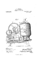
- Figure 1 is a side elevation of a carbonator embodying my invention.
- Fig. 2 is an elevation looking at the opposite side of the carbonator shown in Fig. 1; and
- Fig. 3 is a horizontal sectional view taken on a median line of the mixing tank.
- FIG. 5 designates an elevated support preferably comprising a pair of standards spaced apart upon which the plat-form 6 is rockingly mounted, said platform being pivotally supported intermediate its ends upon the transverse rod 7. It will be manifest that rocking or tilting movement of the platform may take place to alternately elevate and lower the ends thereof, the tilting movement of the platform being preferably limited by suitable stops (not shown) positioned to be engaged by the bottom of the platform at each side of the pivot rod and serving as limiting abutments.
- a mixing tank 8 of any approved shape or construction is mounted upon one end of the platform and adapted to contain a supply of carbonated liquid.
- a motor 9 shown, in the present instance, for purposes of illustration, as an electric motor, although it Will be obvious that any Upon the other type of motor might be employed if found necessary or expedient without detracting from the efiiciency or operation of the apparatus as a whole.
- a standard 12 carries the pump shaft 13 upon which is mounted the gear wheel 14 adapted to mesh with and be driven by a suitable spur-gear 16 mounted on the motor shaft.
- a sprocket wheel 17 is also mounted on the pump shaft and, is equipped with a crank pin 18 to which the piston rod 19 of the pump is connected through the intermediary of the connecting link or links 20.
- the pump is preferably so assembled that the water will be forced from the pump upon the upstroke of the piston, the downstroke of the piston being an idle one.
- a pipe 21 is connected at one end with the discharge port of the pump and at its other end with the hollow plug or connection 22 communicating with the interior of the mixing tank through the bottom thereof.
- a suitable hand-valve 23 is preferably interposed in the pipe 21 to control or regulate the quantity of water supplied to the tank.
- a pipe 24 is connected with the hollow plug 22 on the opposite side from the pipe 21 and, as shown in Fig. 1, is projected above the platform near the center thereof.
- a hose or other connecting means 25 establishes communication between the pipe 24 and a suitable supply of gas under pressure. The gas and water are both introduced into the connection 22 at the bottom of the tank where they are mixed, the gas and water being further mixed as the gas bubbles up through the water in the tank.
- a discharge pipe 26 communicates with the bottom of the connection 22 and terminates at its other end in a nipple 27 which is adapted to be connected with a flexible or other pipe from which the carbonated liquid is withdrawn.
- a controlling valve 28 is interposed in the discharge pipe 26 in accessible position above the tilting platform.
- a water gage or glass 29 of ordinary construction is communicated with the connections 22 and 30 opening into the top and bottom of the tank through the short pipes 31 and 32 respectively.
- a common pressure gage 33 is also preferably attached to the conne tion 30 an a small turning plug 34 may be utilized to shut off communication with the top of the tank if desired.
- the water in the mixing tank is normally maintained at substantially the level shown in dotted lines in Fig. 2.
- a horizontally disposed shaft 35 projecting at each end through the side walls of the tank, suitable packing rings 36 being provided to insure a tight fit between the shaft and the walls of the tank which will prevent the escape of water or gas from the tank.
- an agitator 37 in the form of a perforated plate which is secured to the shaft by means of set-screws 38.
- a sprocket wheel 39 Upon one end of the shaft 35 outside the tank and in alinement with the sprocket wheel 17 there is mounted a sprocket wheel 39 which is connected with the sprocket wheel 17 to be driven therefrom by a chain 40.
- a snap-switch controlling the motor current is mounted upon the motor base as shown in Fig. 1 and is adapted to open and close the motor circuit to start and stop the pump as required.
- This switch may be of any well known or preferred construction but in the present instance I have shown a member 41 pivoted at 42 on the motor base and connected at one end with a rod 43 pivoted to a plate 44 secured upon the adjacent standard or support 5.
- the two terminals 45 and 46 are connected by the stationary bar 47 and the swinging bar 48 to close the circuit.
- A'spring 49 is connected at one end with the bar 48 and at its other end with the lever 41.
- a guide comprising a track 51, guide members 52 and end members 53.
- This guide is disposed across the pivotal axis of the platform and is adapted to receive a weight 54 shown in the present instance in the form of a ball. hen the platform is tilted in one direction or the other this ball will, of course, roll to the lower end of the guide.
- a tilting platform a reservoir mounted on one end thereof, means for supplying the reservoir mounted on the opposite end of said platform, means adapted to be operated upon tilting of the platform in one direction to set in operation the supply means and upon tilting of the platform in the other direction to throw said supply means out of operation, a guide carried by the platform and extending across the platform pivot and a weight mounted on said guide to travel by gravity to the lower end thereof whereby to add its weight to the reservoir or to the supply means as the platform tilts on said pivot.
- a tilting platform mounted on one end thereof, a pump for supplying water to the tank mounted on the other end, means for starting the pump when the platform tilts to elevate the mixing tank and for stopping the pump when the platform tilts to lower the mixing tank, a track disposed across the plat-form fulcrum and a shifting weight mounted on the guide to move by gravity to either side of the plat-form fulcrum whereby its weight for simultaneously actuating said agitator and pump to oausethe agitator to enter the liquid upon the idle stroke of the pump.
- a rocking platform mounted at one end thereof, a single acting pump and a motor mounted at the other end of the platform, a shifting weight adapted to control the rocking movements of the platform, an agitator rotatably mounted in said tank so as to be submerged only during a portion of its revolution, and means connected with said motor for simultaneously operating said pump and agitator whereby the agitator is removed from the liquid in the tank during the active stroke of the pump.
Landscapes
- Chemical & Material Sciences (AREA)
- Chemical Kinetics & Catalysis (AREA)
- Mixers Of The Rotary Stirring Type (AREA)
Description
0. L. BASTIAN.
CARBONATING APPARATUS. APPLIOATION FILED MAR.15,1911.
' 1,056,487, Patented Mar.18,1913.
2 SHEETSSHEET 1.
ZW7Z66666 Jude/W167:
alga/@410 JW *M v G. L. BASTIAN.
' GARBONATING APPARATUS.
CHARLES L. BASTIAN, OF CHICAGO, ILLINOIS.
CARBONATING APPARATUS.
Specification of Letters Patent.
Application filed March 15, 1911.
Patented Mar. 18, 1913. Serial No.,614,557.
To all whom it may concern Be it known that I, CHARLES L. BASTIAN, a citizen of the United States, residing at Chicago, in the county of Cook and State of Illinois, have invented certainnew and useful Improvements in Carbonating Apparatus, of which the following is a specification.
This invention relates to carbonating apparatus particularly designed for manufacturing soda water in drug stores and similar places, but also capable of use for manufacturing carbonated beverages in bottling establishments and elsewhere.
The principal object of the invention is to maintain a constant and predetermined supply of carbonated water and to automatically replenish this supply as fast as it is used up or drawn off.
In order to accomplish this object the invention embodies certain novel features of construction, preferred forms of which are described in the following specification and illustrated in the accompanying drawings throughout the varlous views of which like reference characters refer to similar parts.
In the drawingsFigure 1 is a side elevation of a carbonator embodying my invention. Fig. 2 is an elevation looking at the opposite side of the carbonator shown in Fig. 1; and Fig. 3 is a horizontal sectional view taken on a median line of the mixing tank.
On the drawings 5 designates an elevated support preferably comprising a pair of standards spaced apart upon which the plat-form 6 is rockingly mounted, said platform being pivotally supported intermediate its ends upon the transverse rod 7. It will be manifest that rocking or tilting movement of the platform may take place to alternately elevate and lower the ends thereof, the tilting movement of the platform being preferably limited by suitable stops (not shown) positioned to be engaged by the bottom of the platform at each side of the pivot rod and serving as limiting abutments.
A mixing tank 8 of any approved shape or construction is mounted upon one end of the platform and adapted to contain a supply of carbonated liquid. other end of the platform I have mounted a motor 9 shown, in the present instance, for purposes of illustration, as an electric motor, although it Will be obvious that any Upon the other type of motor might be employed if found necessary or expedient without detracting from the efiiciency or operation of the apparatus as a whole. Adjacent the motor there is mounted a single acting reciprocatory pump 10 of any preferred type, said pump being connected with a suitable source of water supply through an intake pipe 11. A standard 12 carries the pump shaft 13 upon which is mounted the gear wheel 14 adapted to mesh with and be driven by a suitable spur-gear 16 mounted on the motor shaft. A sprocket wheel 17 is also mounted on the pump shaft and, is equipped with a crank pin 18 to which the piston rod 19 of the pump is connected through the intermediary of the connecting link or links 20. The pump is preferably so assembled that the water will be forced from the pump upon the upstroke of the piston, the downstroke of the piston being an idle one.
A pipe 21 is connected at one end with the discharge port of the pump and at its other end with the hollow plug or connection 22 communicating with the interior of the mixing tank through the bottom thereof. A suitable hand-valve 23 is preferably interposed in the pipe 21 to control or regulate the quantity of water supplied to the tank. A pipe 24 is connected with the hollow plug 22 on the opposite side from the pipe 21 and, as shown in Fig. 1, is projected above the platform near the center thereof. A hose or other connecting means 25 establishes communication between the pipe 24 and a suitable supply of gas under pressure. The gas and water are both introduced into the connection 22 at the bottom of the tank where they are mixed, the gas and water being further mixed as the gas bubbles up through the water in the tank. A discharge pipe 26 communicates with the bottom of the connection 22 and terminates at its other end in a nipple 27 which is adapted to be connected with a flexible or other pipe from which the carbonated liquid is withdrawn. A controlling valve 28 is interposed in the discharge pipe 26 in accessible position above the tilting platform. A water gage or glass 29 of ordinary construction is communicated with the connections 22 and 30 opening into the top and bottom of the tank through the short pipes 31 and 32 respectively. A common pressure gage 33 is also preferably attached to the conne tion 30 an a small turning plug 34 may be utilized to shut off communication with the top of the tank if desired.
The water in the mixing tank is normally maintained at substantially the level shown in dotted lines in Fig. 2. At approximately this level I have mounted a horizontally disposed shaft 35 projecting at each end through the side walls of the tank, suitable packing rings 36 being provided to insure a tight fit between the shaft and the walls of the tank which will prevent the escape of water or gas from the tank. Upon this shaft and within the tank I have mounted an agitator 37 in the form of a perforated plate which is secured to the shaft by means of set-screws 38. Upon one end of the shaft 35 outside the tank and in alinement with the sprocket wheel 17 there is mounted a sprocket wheel 39 which is connected with the sprocket wheel 17 to be driven therefrom by a chain 40. The most satisfactory results are obtained by connecting the shafts 35 and 13 through the chain 40 in their relative relation shown in Fig. 2, that is, when the pump piston has reached the limit of its downstroke the'agitator 37 is just withdrawn from the liquid in the tank so that during the upward or active stroke of the pump piston, when the shaft rotates in the direction of the arrow in Fig. 2, the agitator is entirely removed from the liquid and travels without resistance in the tank. When now the pump piston has reached its extreme upward movement and begins to move downwardly on its idle stroke the agitator is submerged in the liquid and stirs up and churns the liquid to thoroughly miX the gas therewith during half of the revolution of the shafts 35 and 13. It will thus be apparent that when the pump piston is acting the agitator is moving idly and when the agitator is operating under the water the pump piston is moving downward on its idle stroke. This arrangement of the parts prevents variations in the speed of the motor and insures a smooth and quiet running apparatus.
A snap-switch controlling the motor current is mounted upon the motor base as shown in Fig. 1 and is adapted to open and close the motor circuit to start and stop the pump as required. This switch may be of any well known or preferred construction but in the present instance I have shown a member 41 pivoted at 42 on the motor base and connected at one end with a rod 43 pivoted to a plate 44 secured upon the adjacent standard or support 5. The two terminals 45 and 46 are connected by the stationary bar 47 and the swinging bar 48 to close the circuit. A'spring 49 is connected at one end with the bar 48 and at its other end with the lever 41. It will be obvious that when the lever 41 is tilted to elevate the end connected with the spring above the pivot of the bar 48, said bar will be withdrawn from the terminal 45 thus breaking the circuit and that when the lever 41 is tilted in the opposite direction to the position shown on the drawings the bar 48 will be drawn by the spring 49 into contact with the terminal 45. The position of the outer end of the lever 41 upon the rod 43 is determined by the adjustable nuts 50 threaded thereon. When the platform is in the position shown in the figures the switch will be closed and the motors will be actuated to operate the pump and the agitator. \Vhen suilicient water has been supplied to the mixing tank to overbalance the weight supported upon the opposite end of the platform the tank end will be lowered and the opposite end elevated. This movement will swing the switch lever 41 about its pivot and open the switch thereby stopping the motor and shutting off the water supply to the tank. \Vhen the carbonated liquid has been withdrawn from the tank until the motor end of the platform overbalances the tank end the platform will again tilt to the position shown in the drawings and the pump will again be started.
In order that the platform may not be continually tilting back and forth to start and stop the pump as the result of slight variations of the level of liquid in the tank I have provided means for controlling movements of the platform so that it will tilt only after a substantial quantity of liquid has been removed or admitted into the tank. Upon the platform there is secured a guide comprising a track 51, guide members 52 and end members 53. This guide is disposed across the pivotal axis of the platform and is adapted to receive a weight 54 shown in the present instance in the form of a ball. hen the platform is tilted in one direction or the other this ball will, of course, roll to the lower end of the guide. In this position its weight will be added to the weight of the other apparatus carried on that end of the platform and a quantity of water sufiicient to overcome the weight of the ball will necessarily have to be admitted or withdrawn from the tank before any tilting movement of the platform can take place. After the platform tilts the ball, of course, will roll to the other end of the guide and its weight will there be added to the weight of the apparatus at that end so that a correspondingly increased difference in weight between the two ends must be established before the reverse tilting movement can take place. The movable weight thus acts as a governor to control the tilting movements of the platform and prevent continuous tilting such as would result from slight variations of the liquid level in the tank.
It is thought that the construction and operation of this invention will be understood from the foregoing without further description and it will be obvious that various changes in the size, shape and proportion of the various parts may be resorted to without departing from the spirit or sacrificing any of the advantages of the invention.
I claim:
1. In a carbonating apparatus, the combination of a tilting platform, a reservoir mounted on one end thereof, means for supplying the reservoir mounted on the opposite end of said platform, means adapted to be operated upon tilting of the platform in one direction to set in operation the supply means and upon tilting of the platform in the other direction to throw said supply means out of operation, a guide carried by the platform and extending across the platform pivot and a weight mounted on said guide to travel by gravity to the lower end thereof whereby to add its weight to the reservoir or to the supply means as the platform tilts on said pivot.
2. In a carbonating apparatus, the combination of a tilting platform, a mixing tank mounted on one end thereof, a pump for supplying water to the tank mounted on the other end, means for starting the pump when the platform tilts to elevate the mixing tank and for stopping the pump when the platform tilts to lower the mixing tank, a track disposed across the plat-form fulcrum and a shifting weight mounted on the guide to move by gravity to either side of the plat-form fulcrum whereby its weight for simultaneously actuating said agitator and pump to oausethe agitator to enter the liquid upon the idle stroke of the pump.
5. In a carbonating apparatus, the combination of a rocking platform, a mixing'tank mounted at one end thereof, a single acting pump and a motor mounted at the other end of the platform, a shifting weight adapted to control the rocking movements of the platform, an agitator rotatably mounted in said tank so as to be submerged only during a portion of its revolution, and means connected with said motor for simultaneously operating said pump and agitator whereby the agitator is removed from the liquid in the tank during the active stroke of the pump.
CHARLES L. BASTIAN.
Witnesses:
WM. 0. BELT, M. A. KIDDIE.
Copies of this patent may be obtained for five cents each, by addressing the Commissioner of Patents, Washington, D. G.
Priority Applications (1)
| Application Number | Priority Date | Filing Date | Title |
|---|---|---|---|
| US61455711A US1056487A (en) | 1911-03-15 | 1911-03-15 | Carbonating apparatus. |
Applications Claiming Priority (1)
| Application Number | Priority Date | Filing Date | Title |
|---|---|---|---|
| US61455711A US1056487A (en) | 1911-03-15 | 1911-03-15 | Carbonating apparatus. |
Publications (1)
| Publication Number | Publication Date |
|---|---|
| US1056487A true US1056487A (en) | 1913-03-18 |
Family
ID=3124741
Family Applications (1)
| Application Number | Title | Priority Date | Filing Date |
|---|---|---|---|
| US61455711A Expired - Lifetime US1056487A (en) | 1911-03-15 | 1911-03-15 | Carbonating apparatus. |
Country Status (1)
| Country | Link |
|---|---|
| US (1) | US1056487A (en) |
Cited By (1)
| Publication number | Priority date | Publication date | Assignee | Title |
|---|---|---|---|---|
| US3196627A (en) * | 1962-05-03 | 1965-07-27 | Sweden Freezer Mfg Co | Automatic mix feed system for dispensing freezers |
-
1911
- 1911-03-15 US US61455711A patent/US1056487A/en not_active Expired - Lifetime
Cited By (1)
| Publication number | Priority date | Publication date | Assignee | Title |
|---|---|---|---|---|
| US3196627A (en) * | 1962-05-03 | 1965-07-27 | Sweden Freezer Mfg Co | Automatic mix feed system for dispensing freezers |
Similar Documents
| Publication | Publication Date | Title |
|---|---|---|
| US2499715A (en) | Water actuated motor | |
| US620820A (en) | Automatic keg-soaking apparatus | |
| US639633A (en) | Carbonating apparatus. | |
| US676406A (en) | Carbonator. | |
| US518577A (en) | Apparatus for making carbonated beverages | |
| US1026715A (en) | Carbonating apparatus. | |
| US757375A (en) | Carbonator. | |
| US552872A (en) | Fluid-motor | |
| US805530A (en) | Oil-pump. | |
| US1216403A (en) | Fuel-mixer. | |
| US613376A (en) | erlanger | |
| US249678A (en) | Automatic sirup-dasher | |
| US620830A (en) | baynes | |
| US1090157A (en) | Carbonator. | |
| US1489779A (en) | Pump | |
| US653499A (en) | Oil-can. | |
| US1295446A (en) | Pneumatic water-elevator. | |
| US244628A (en) | Water motor | |
| US492723A (en) | Apparatus for controlling pumps | |
| US736523A (en) | Carbonating apparatus. | |
| US445705A (en) | Water-motor | |
| US1042226A (en) | Pumping apparatus. | |
| US343015A (en) | Churning device | |
| US1080471A (en) | Air-gas apparatus. | |
| US1102612A (en) | Belt-shifter. |