US10563835B2 - Vehicle headlamp and vehicle using same - Google Patents
Vehicle headlamp and vehicle using same Download PDFInfo
- Publication number
- US10563835B2 US10563835B2 US16/096,285 US201716096285A US10563835B2 US 10563835 B2 US10563835 B2 US 10563835B2 US 201716096285 A US201716096285 A US 201716096285A US 10563835 B2 US10563835 B2 US 10563835B2
- Authority
- US
- United States
- Prior art keywords
- lens
- exit
- vehicle
- light
- entrance
- Prior art date
- Legal status (The legal status is an assumption and is not a legal conclusion. Google has not performed a legal analysis and makes no representation as to the accuracy of the status listed.)
- Active
Links
- 230000003287 optical effect Effects 0.000 claims description 6
- 230000007423 decrease Effects 0.000 description 15
- 238000004088 simulation Methods 0.000 description 8
- 239000011347 resin Substances 0.000 description 6
- 229920005989 resin Polymers 0.000 description 6
- 238000013041 optical simulation Methods 0.000 description 4
- 230000003247 decreasing effect Effects 0.000 description 3
- 239000000463 material Substances 0.000 description 3
- 239000004925 Acrylic resin Substances 0.000 description 2
- 229920000178 Acrylic resin Polymers 0.000 description 2
- 230000003044 adaptive effect Effects 0.000 description 2
- 238000000034 method Methods 0.000 description 2
- 238000000465 moulding Methods 0.000 description 2
- 229920003229 poly(methyl methacrylate) Polymers 0.000 description 2
- 229920005668 polycarbonate resin Polymers 0.000 description 2
- 239000004431 polycarbonate resin Substances 0.000 description 2
- 239000004926 polymethyl methacrylate Substances 0.000 description 2
- 238000013459 approach Methods 0.000 description 1
Images


Classifications
-
- F—MECHANICAL ENGINEERING; LIGHTING; HEATING; WEAPONS; BLASTING
- F21—LIGHTING
- F21S—NON-PORTABLE LIGHTING DEVICES; SYSTEMS THEREOF; VEHICLE LIGHTING DEVICES SPECIALLY ADAPTED FOR VEHICLE EXTERIORS
- F21S41/00—Illuminating devices specially adapted for vehicle exteriors, e.g. headlamps
- F21S41/20—Illuminating devices specially adapted for vehicle exteriors, e.g. headlamps characterised by refractors, transparent cover plates, light guides or filters
- F21S41/25—Projection lenses
-
- B—PERFORMING OPERATIONS; TRANSPORTING
- B60—VEHICLES IN GENERAL
- B60Q—ARRANGEMENT OF SIGNALLING OR LIGHTING DEVICES, THE MOUNTING OR SUPPORTING THEREOF OR CIRCUITS THEREFOR, FOR VEHICLES IN GENERAL
- B60Q1/00—Arrangement of optical signalling or lighting devices, the mounting or supporting thereof or circuits therefor
- B60Q1/0011—Arrangement of optical signalling or lighting devices, the mounting or supporting thereof or circuits therefor with light guides for distributing the light between several lighting or signalling devices
-
- B—PERFORMING OPERATIONS; TRANSPORTING
- B60—VEHICLES IN GENERAL
- B60Q—ARRANGEMENT OF SIGNALLING OR LIGHTING DEVICES, THE MOUNTING OR SUPPORTING THEREOF OR CIRCUITS THEREFOR, FOR VEHICLES IN GENERAL
- B60Q1/00—Arrangement of optical signalling or lighting devices, the mounting or supporting thereof or circuits therefor
- B60Q1/02—Arrangement of optical signalling or lighting devices, the mounting or supporting thereof or circuits therefor the devices being primarily intended to illuminate the way ahead or to illuminate other areas of way or environments
- B60Q1/04—Arrangement of optical signalling or lighting devices, the mounting or supporting thereof or circuits therefor the devices being primarily intended to illuminate the way ahead or to illuminate other areas of way or environments the devices being headlights
-
- F—MECHANICAL ENGINEERING; LIGHTING; HEATING; WEAPONS; BLASTING
- F21—LIGHTING
- F21S—NON-PORTABLE LIGHTING DEVICES; SYSTEMS THEREOF; VEHICLE LIGHTING DEVICES SPECIALLY ADAPTED FOR VEHICLE EXTERIORS
- F21S41/00—Illuminating devices specially adapted for vehicle exteriors, e.g. headlamps
- F21S41/10—Illuminating devices specially adapted for vehicle exteriors, e.g. headlamps characterised by the light source
- F21S41/14—Illuminating devices specially adapted for vehicle exteriors, e.g. headlamps characterised by the light source characterised by the type of light source
- F21S41/141—Light emitting diodes [LED]
- F21S41/143—Light emitting diodes [LED] the main emission direction of the LED being parallel to the optical axis of the illuminating device
-
- F—MECHANICAL ENGINEERING; LIGHTING; HEATING; WEAPONS; BLASTING
- F21—LIGHTING
- F21S—NON-PORTABLE LIGHTING DEVICES; SYSTEMS THEREOF; VEHICLE LIGHTING DEVICES SPECIALLY ADAPTED FOR VEHICLE EXTERIORS
- F21S41/00—Illuminating devices specially adapted for vehicle exteriors, e.g. headlamps
- F21S41/10—Illuminating devices specially adapted for vehicle exteriors, e.g. headlamps characterised by the light source
- F21S41/14—Illuminating devices specially adapted for vehicle exteriors, e.g. headlamps characterised by the light source characterised by the type of light source
- F21S41/141—Light emitting diodes [LED]
- F21S41/151—Light emitting diodes [LED] arranged in one or more lines
-
- F—MECHANICAL ENGINEERING; LIGHTING; HEATING; WEAPONS; BLASTING
- F21—LIGHTING
- F21S—NON-PORTABLE LIGHTING DEVICES; SYSTEMS THEREOF; VEHICLE LIGHTING DEVICES SPECIALLY ADAPTED FOR VEHICLE EXTERIORS
- F21S41/00—Illuminating devices specially adapted for vehicle exteriors, e.g. headlamps
- F21S41/20—Illuminating devices specially adapted for vehicle exteriors, e.g. headlamps characterised by refractors, transparent cover plates, light guides or filters
- F21S41/285—Refractors, transparent cover plates, light guides or filters not provided in groups F21S41/24 - F21S41/2805
-
- F—MECHANICAL ENGINEERING; LIGHTING; HEATING; WEAPONS; BLASTING
- F21—LIGHTING
- F21S—NON-PORTABLE LIGHTING DEVICES; SYSTEMS THEREOF; VEHICLE LIGHTING DEVICES SPECIALLY ADAPTED FOR VEHICLE EXTERIORS
- F21S41/00—Illuminating devices specially adapted for vehicle exteriors, e.g. headlamps
- F21S41/30—Illuminating devices specially adapted for vehicle exteriors, e.g. headlamps characterised by reflectors
- F21S41/32—Optical layout thereof
- F21S41/322—Optical layout thereof the reflector using total internal reflection
-
- F—MECHANICAL ENGINEERING; LIGHTING; HEATING; WEAPONS; BLASTING
- F21—LIGHTING
- F21S—NON-PORTABLE LIGHTING DEVICES; SYSTEMS THEREOF; VEHICLE LIGHTING DEVICES SPECIALLY ADAPTED FOR VEHICLE EXTERIORS
- F21S41/00—Illuminating devices specially adapted for vehicle exteriors, e.g. headlamps
- F21S41/60—Illuminating devices specially adapted for vehicle exteriors, e.g. headlamps characterised by a variable light distribution
- F21S41/65—Illuminating devices specially adapted for vehicle exteriors, e.g. headlamps characterised by a variable light distribution by acting on light sources
- F21S41/663—Illuminating devices specially adapted for vehicle exteriors, e.g. headlamps characterised by a variable light distribution by acting on light sources by switching light sources
Definitions
- the present disclosure relates to a vehicle headlamp and a vehicle using the same.
- a vehicle headlamp (also referred to as a headlamp or a headlight) generally includes a high beam (running headlamp) and a low beam (passing headlamp) (for example, PTL 1).
- the high beam can irradiate a wide range of a front of a vehicle, but give dazzle to a driver of an oncoming vehicle.
- the low beam does not give dazzle to the driver of the oncoming vehicle, but there is a problem that the low beam cannot irradiate a wide range of the front of the vehicle.
- ADB adaptive driving beam
- high beam SW of the vehicle headlamp of the related art using the ADB system includes a plurality of LED light source modules M 1 to M 4 as light emitting elements and a plurality of lenses S 1 to S 4 for emitting the lights generated from LED light source modules M 1 to M 4 in a desired direction.
- Focal points of lenses S 1 to S 4 are generally positioned on light emitting surfaces of LED light source modules M 1 to M 4 . Therefore, the lights generated from LED light source modules M 1 to M 4 become parallel lights through lenses S 1 to S 4 .
- LED light source modules M 1 to M 4 of high beam SW are automatically switched on and off respectively when the camera detects the presence of the oncoming vehicle or the preceding vehicle. In this way, an irradiation range of high beam SW of the vehicle headlamp is controlled.
- the lights emitted from lenses S 1 to S 4 are the parallel lights, light and dark between the irradiation range and a portion that is not in the irradiation range is clearly distinguished.
- a positional deviation of light distribution characteristics of lenses S 1 to S 4 occurs due to vibration or temperature changes of lenses S 1 to S 4 , assembly errors of the vehicle headlamp, or the like.
- the light distribution characteristics of the lens indicate a relationship between a direction of the light emitted from the lens and a luminous intensity distribution in the direction. Light distribution unevenness occurs due to the positional deviation of the light distribution characteristics.
- An object of the present disclosure is to realize a vehicle headlamp capable of suppressing light distribution unevenness even if positional deviation of light distribution characteristics of a lens occurs.
- a vehicle headlamp including: a plurality of light emitting elements; a plurality of first lenses; and a plurality of second lenses.
- Each of the plurality of first lenses is provided corresponding to each of the plurality of light emitting elements, includes a first lens entrance and a first lens exit, and is configured to converge lights entered the first lens entrance from the each of the plurality of light emitting elements on the first lens exit.
- Each of the plurality of second lenses is provided corresponding to each of the plurality of light emitting elements, and includes a second lens entrance facing the first lens exit and a second lens exit having a projection shape for forming a focal point. The focal point of the second lens is positioned at a side of the second lens ahead the first lens exit of the first lens.
- the focal point of the second lens is positioned on an inside of the second lens, so that the focal point of the second lens is positioned on a front side of a vehicle from the first lens exit of the first lens. Therefore, the light entering the second lens entrance of the second lens is not a parallel light but is emitted from the second lens in a state of being inclined toward a center of the vehicle. Therefore, light and dark between an irradiation range and a non-irradiation range of the light becomes blurred. Therefore, even if positional deviation of the light distribution characteristics occurs, light distribution unevenness can be suppressed.
- FIG. 1 is a front view of a vehicle including a vehicle headlamp according to Embodiment 1.
- FIG. 2A is a plan view of a high beam of the vehicle headlamp according to Embodiment 1.
- FIG. 2B is a perspective view of the high beam of the vehicle headlamp according to Embodiment 1.
- FIG. 3A is a schematic view of an irradiation range of light when a right high beam of the vehicle headlamp according to Embodiment 1 is fully lit.
- FIG. 3B is a schematic view of an irradiation range of the light when a left high beam of the vehicle headlamp according to Embodiment 1 is fully lit.
- FIG. 3C is a schematic view of an irradiation range of the light when both right and left high beams of the vehicle headlamps according to Embodiment 1 are fully lit.
- FIG. 4 is a view illustrating light distribution characteristics when the both right and left high beams of the vehicle headlamps according to Embodiment 1 are fully lit.
- FIG. 5A is a plan view of a lens unit of the vehicle headlamp according to Embodiment 1.
- FIG. 5B is a view for explaining a cross section in a plane direction of the lens unit of the vehicle headlamp according to Embodiment 1.
- FIG. 5C is a view for explaining the cross section in the plane direction of a first lens of the vehicle headlamp according to Embodiment 1.
- FIG. 6A is a schematic view illustrating a relationship between a focal point of a second lens of the high beam of the vehicle headlamp according to Embodiment 1 and light emitted from a second lens exit of the second lens.
- FIG. 6B is a schematic view illustrating a relationship between a focal point of a second lens of a high beam of a vehicle headlamp of the related art and light emitted from the second lens.
- FIG. 6C is a schematic view illustrating a relationship between a focal point of a second lens of a high beam of a vehicle headlamp according to another example of Embodiment 1 and light emitted from a second lens exit of the second lens.
- FIG. 7 is a graph illustrating light distribution characteristics of the lens unit, in which a solid line indicates a case of the lens unit of the vehicle headlamp according to Embodiment 1 and a broken line indicates a case of a lens unit of the vehicle headlamp of the related art.
- FIG. 8A is a graph illustrating light distribution characteristics of two lens units in a state where there is no positional deviation and combined light distribution characteristics thereof in the vehicle headlamp according to Embodiment 1.
- FIG. 8B is a graph illustrating the light distribution characteristics of two lens units in a state where there is the positional deviation and combined light distribution characteristics thereof in the vehicle headlamp according to Embodiment 1.
- FIG. 8C is a graph illustrating light distribution characteristics of two lens units in a state where there is no positional deviation and combined light distribution characteristics thereof in the vehicle headlamp of the related art.
- FIG. 8D is a graph illustrating light distribution characteristics of two lens units in a state where there is the positional deviation and combined light distribution characteristics in the vehicle headlamp of the related art.
- FIG. 9A is a graph illustrating a simulation result of the irradiation range of the light when an LED corresponding to a lens unit is lit by using one lens unit in the vehicle headlamp according to Embodiment 1.
- FIG. 9B is a graph illustrating a simulation result of the light distribution characteristics in a horizontal direction in a cross section 9 Aa- 9 Ab of FIG. 9A .
- FIG. 10A is a right side view of a lens unit of a vehicle headlamp according to Embodiment 2.
- FIG. 10B is an enlarged plan view of a first lens exit of a first lens of the lens unit according to Embodiment 2.
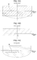
- FIG. 11A is a schematic graph of an irradiation range of the light when general low beams are fully lit.
- FIG. 11B is a schematic graph of an irradiation range of the light when high beams of the related art are fully lit.
- FIG. 11C is a schematic graph of an irradiation range of the light when general low beams and the high beams of the related art are fully lit.
- FIG. 11D is a schematic graph of an irradiation range of the light when high beams of the vehicle headlamp according to Embodiment 2 are fully lit.
- FIG. 11E is a schematic graph of an irradiation range of the light when general low beams and the high beams of the vehicle headlamp according to Embodiment 2 are fully lit.
- FIG. 12A is a graph illustrating a simulation result of an irradiation range of the light when an LED corresponding to a lens unit is lit by using one lens unit in the vehicle headlamp according to Embodiment 2.
- FIG. 12B is a graph illustrating a simulation result of light distribution characteristics in a height direction in a cross section of 12 Aa- 12 Ab of FIG. 12A .
- FIG. 13 is a perspective view of the high beam of the vehicle headlamp of the related art.
- Embodiment 1 a vehicle headlamp according to Embodiment 1 will be described with reference to FIGS. 1 to 9B .
- FIG. 1 is a front view of vehicle 1 including vehicle headlamp 2 according to Embodiment 1.
- FIG. 1 is a view of vehicle 1 as viewed from a front thereof.
- a forward direction of vehicle 1 is referred to as a front side
- a backward direction is referred to as a back side
- a right direction is referred to as a right side
- a left direction is referred to as a left side.
- a surface on the front side of vehicle 1 is referred to as a front surface.
- Vehicle headlamps 2 are attached to right and left sides in the front surface of vehicle 1 one by one symmetrically in positions lower than a viewpoint of the driver.
- Vehicle headlamp 2 is configured of high beam 3 (running headlamp) and low beam 4 (passing headlamp).
- FIG. 2A is a plan view of high beam 3 of vehicle headlamp 2 of the right side (left side of the page of FIG. 1 ) of vehicle 1 according to Embodiment 1.
- an upper side of the page is the front side of vehicle 1 and a lower side of the page is the back side of the vehicle.
- FIG. 2B is a perspective view of high beam 3 of vehicle headlamp 2 according to Embodiment 1.
- FIG. 2B is a view of high beam 3 as viewed from a direction different from FIG. 2A .
- High beam 3 includes a plurality of light emitting diodes (LEDs) 22 a to 22 g which are light emitting elements, a plurality of LED boards 25 on which LEDs 22 a to 22 g are mounted, board 21 which holds the plurality of LED boards 25 , and a plurality of lens units 30 a to 30 g which are disposed on LED boards 25 .
- One lens unit 30 is provided on one LED 22 .
- reference numeral 30 indicates one of the plurality of lens units 30 a to 30 g and reference numeral 22 indicates one of the plurality of LEDs 22 a to 22 g.
- FIG. 3A is a schematic view of an irradiation range of light when right high beam 3 of vehicle headlamp 2 according to Embodiment 1 is fully lit.
- Symbols AR to GR of FIG. 3A indicate the irradiation ranges of the light generated from respective LEDs 22 a to 22 g of high beam 3 of right vehicle headlamp 2 of vehicle 1 .
- a horizontal axis indicates an angle (hereinafter, referred to as a horizontal angle) inclined in a horizontal direction from a center of vehicle 1 when the center is 0°.
- a vertical axis indicates an angle (hereinafter, referred to as an elevation angle) inclined in a height direction from a horizontal plane passing through high beam 3 when the horizontal plane is 0°.
- a center point of the angle is a center of a front end of vehicle 1 for both the elevation angle and the horizontal angle.
- the arrangement (position) of LEDs 22 a to 22 g and the position of the irradiation range of the light are irrelevant and the irradiation ranges of respective LEDs 22 a to 22 g are adjusted by lens units 30 a to 30 g .
- lens units 30 a to 30 g For example, as illustrated in FIG.
- irradiation ranges AR and BR of LEDs 22 a and 22 b are the horizontal angle 0 ⁇ 2°
- irradiation range CR of LED 22 c is the horizontal angle ⁇ 1 ⁇ 2°
- irradiation range DR of LED 22 d is the horizontal angle 1 ⁇ 2°
- irradiation range ER of LED 22 e is the horizontal angle 3 ⁇ 2°
- irradiation range FR of LED 22 f is the horizontal angle 3 to 8°
- irradiation range GR of LED 22 g is the horizontal angle 5 to 12°.
- FIG. 3B is a schematic view of an irradiation range of the light when left high beam 3 of vehicle headlamp 2 according to Embodiment 1 is fully lit.
- Symbols AL to GL of FIG. 3B indicate the irradiation ranges of the light generated from LEDs of high beam 3 of left vehicle headlamp 2 of vehicle 1 , and the irradiation ranges are bilaterally symmetrical with the irradiation ranges of right high beam 3 illustrated in FIG. 3A with the center (horizontal angle 0°) of vehicle 1 as an axis.
- FIG. 3C is a schematic view of an irradiation range of the light when both right and left high beams 3 of vehicle headlamps 2 according to Embodiment 1 are fully lit. In other words, FIG.
- FIG. 4 is a view illustrating light distribution characteristics when the both right and left high beams 3 of vehicle headlamps 2 according to Embodiment 1 are fully lit.
- FIG. 4 illustrates luminous intensity distribution with respect to the irradiation range (horizontal angle), that is, the light distribution characteristics of lens units 30 a to 30 g in the horizontal direction when both right and left high beams 3 are fully lit.
- Adaptive Driving Beam when a camera placed on the vehicle detects an oncoming vehicle or a preceding vehicle, ON and OFF of each of LEDs 22 a to 22 g is automatically controlled and the irradiation range of the light is controlled, so that it is possible not to give dazzle to a driver.
- ADB Adaptive Driving Beam
- FIG. 5A is a plan view of lens unit 30 of vehicle headlamp 2 according to Embodiment 1.
- FIG. 5B is a view for explaining a cross section in a plane direction of lens unit 30 of vehicle headlamp 2 according to Embodiment 1.
- FIG. 5C is a view for explaining the cross section in the plane direction of first lens 23 of vehicle headlamp 2 according to Embodiment 1.
- lens unit 30 includes first lens 23 and second lens 24 .
- Second lens 24 is disposed in front of first lens 23 .
- First lens 23 is elongated in a forward and backward direction.
- First lens exit 36 is provided at a front end of first lens 23 and first lens entrance 31 is provided at a back end thereof.
- recess portion 31 a surrounding LED 22 is provided in first lens entrance 31 .
- first entrance surface 32 is provided on a bottom surface of recess portion 31 a and second entrance surface 33 is provided on a side surface of recess portion 31 a .
- First entrance surface 32 has a projection shape toward LED 22 .
- first lens 23 has a two-stage configuration of first reflection surface 34 on a back side and second reflection surface 35 on a front side.
- First reflection surface 34 has a tapered shape of which a width decreases toward the back side and second reflection surface 35 has a tapered shape of which a width decreases toward the front side.
- a shape of first lens exit 36 of first lens 23 has a rectangular shape.
- first lens exit 36 has a flat shape.
- first lens 23 is made of a transparent resin such as an acrylic resin or a polycarbonate resin as a material by a general resin molding method.
- the light generated and diverged from LED 22 first enters first entrance surface 32 provided on the bottom surface of recess portion 31 a or second entrance surface 33 provided on the side surface of recess portion 31 a .
- optical path L 1 passing through a center of first entrance surface 32 directly goes straight and reaches first lens exit 36 of first lens 23 .
- Optical path L 2 passing through a position slightly shifted from the center of first entrance surface 32 is refracted toward the center by first entrance surface 32 having the projection shape, and then directly goes straight to reach first lens exit 36 .
- Optical path L 3 passing through a position slightly shifted from the center of first entrance surface 32 is refracted by first entrance surface 32 having the projection shape, and then totally reflected by second reflection surface 35 to reach first lens exit 36 .
- Optical path L 4 passing through second entrance surface 33 is refracted by second entrance surface 33 , and then totally reflected by first reflection surface 34 , and is further totally reflected by second reflection surface 35 to reach first lens exit 36 .
- first lens 23 guides the light generated from LED 22 to second lens 24 using first lens exit 36 as a secondary light source.
- FIG. 6A is a schematic view illustrating a relationship between focal point 61 of second lens 24 of high beam 3 of vehicle headlamp 2 according to Embodiment 1 and the light emitted from second lens exit 38 of second lens 24 .
- second lens 24 includes second lens entrance 37 and second lens exit 38 .
- Second lens entrance 37 of second lens 24 has a flat shape and faces first lens exit 36 of first lens 23 so as to be parallel thereto within a gap therebetween.
- Second lens exit 38 of second lens 24 has a projection shape toward the front side of the vehicle.
- second lens 24 is also made of a transparent resin such as an acrylic resin or a polycarbonate resin as a material by a general resin molding method.
- focal point 61 of second lens 24 is positioned on an inside of second lens 24 . That is, focal point 61 of second lens 24 is positioned on a front side (second lens 24 side) from first lens exit 36 of first lens 23 .
- FIG. 6B is a schematic view illustrating a relationship between focal point 61 a of second lens 24 of high beam 3 of vehicle headlamp 2 of the related art and light emitted from second lens 24 .
- focal point 61 a of second lens 24 is positioned in first lens exit 36 of first lens 23 .
- the light entered second lens entrance 37 of second lens 24 using first lens exit 36 of first lens 23 as a secondary light source is substantially parallel light and emitted from second lens exit 38 of second lens 24 . Therefore, light and dark between the irradiation range of the light and the non-irradiation range are clearly distinguished.
- FIG. 7 is a graph illustrating light distribution characteristics of the lens unit, in which a solid line indicates a case of lens unit 30 of vehicle headlamp 2 according to Embodiment 1 and a broken line indicates a case of a lens unit of the vehicle headlamp of the related art.
- the light distribution characteristics of the lens unit of the related art are distributed in a top hat type as illustrated in a broken line in FIG. 7 .
- a horizontal angle in FIG. 7 is configured such that the center of lens unit 30 is set to 0°.
- focal point 61 of second lens 24 is positioned on second lens 24 side from first lens exit 36 of first lens 23 , so that the light entered second lens entrance 37 of second lens 24 using first lens exit 36 of first lens 23 as the secondary light source is not the parallel light and is emitted from second lens exit 38 in a state of being inclined toward the center of lens unit 30 .
- the light distribution characteristics of lens unit 30 of high beam 3 of vehicle headlamp 2 according to the embodiment have a gentle distribution close to a Gaussian distribution in which the luminous intensity is a peak at the center (horizontal angle 0°) of lens unit 30 as illustrated in the solid line in FIG. 7 .
- FIG. 8A illustrates light distribution characteristics of two lens units 30 c and 30 e in high beam 3 of vehicle headlamp 2 according to Embodiment 1.
- FIG. 8A is a graph illustrating the light distribution characteristics of two lens units 30 in a state where there is no positional deviation and combined light distribution characteristics thereof in vehicle headlamp 2 according to Embodiment 1.
- Reference numeral 81 indicates the light distribution characteristics of lens unit 30 c
- reference numeral 82 indicates the light distribution characteristics of lens unit 30 e
- reference numeral 83 indicates the combined light distribution characteristics obtained by superposing the light distribution characteristics 81 of lens unit 30 c and the light distribution characteristics 82 of lens unit 30 e.
- FIG. 8B is a graph illustrating the light distribution characteristics of two lens units 30 c and 30 e similar to the case of FIG. 8A , and illustrating the light distribution characteristics of two lens units in a state where there is the positional deviation and combined light distribution characteristics thereof in the vehicle headlamp according to Embodiment 1 which is different from FIG. 8A .
- light distribution characteristics 81 of lens unit 30 c are displaced by the horizontal angle of 0.2° with respect to light distribution characteristics 82 of lens unit 30 e .
- Such a positional deviation of the light distribution characteristics is generated, for example, by vibration or a temperature change of lens unit 30 , an assembly error of vehicle headlamp 2 , or the like.
- Reference numeral 84 indicates the combined light distribution characteristics of two lens units 30 c and 30 e.
- FIG. 8C is a graph illustrating the light distribution characteristics of two lens units similar to the case of FIG. 8A , not illustrating the vehicle headlamp according to the embodiment, but illustrating the light distribution characteristics of the vehicle headlamp of the related art.
- FIG. 8C is a graph illustrating the light distribution characteristics of two lens units in a state where there is no positional deviation and combined light distribution characteristics thereof in the vehicle headlamp of the related art.
- Reference numeral 85 indicates the light distribution characteristics of the lens unit of the related art provided at a position corresponding to the position of lens unit 30 c and illustrated in FIG. 6B
- reference numeral 86 indicates the light distribution characteristics of the lens unit of the related art provided at a position corresponding to the position of lens unit 30 e and illustrated in FIG. 6B
- reference numeral 87 indicates the combined light distribution characteristics of the two lens units.
- FIG. 8D is a graph illustrating the light distribution characteristics of the vehicle headlamp of the related art similar to the case of FIG. 8C , and illustrating the light distribution characteristics of two lens units in a state where there is the positional deviation and combined light distribution characteristics thereof in the vehicle headlamp of the related art which is different from FIG. 8C .
- light distribution characteristics 85 are displaced by the horizontal angle of 0.2° with respect to light distribution characteristics 86 .
- Reference numeral 88 indicates the combined light distribution characteristics of the two lens units.
- FIG. 9A is a graph illustrating a simulation result of the irradiation range of the light when LED 22 corresponding to lens unit 30 is lit by using one lens unit 30 in vehicle headlamp 2 according to Embodiment 1.
- a distance between focal point 61 and principal point 62 of second lens 24 that is, focal distance f (see FIG. 6A ) is 42 mm and distance a (see FIG. 6A ) between focal point 61 of second lens 24 and first lens exit 36 of first lens 23 is 5 mm.
- FIG. 9B is a graph illustrating a simulation result of the light distribution characteristics in the horizontal direction in a cross section 9 Aa- 9 Ab of FIG. 9A .
- FIG. 9B illustrates a relationship between the horizontal angle (horizontal axis) and the luminous intensity (vertical axis) in the elevation angle 0°, that is, the light distribution characteristics of lens unit 30 in the horizontal direction.
- a half value width is ⁇ 2°, it can be seen that the light distribution characteristics gently change from the horizontal angle 0° which is the peak of the luminous intensity.
- a/f is approximately 0.12.
- a change rate of the light distribution characteristics increases, that is, it approaches the top hat type distribution of the related art.
- the change rate of the light distribution characteristics decreases, but if the value of a/f is too large, the light distribution characteristics expand in the horizontal direction unnecessarily. Therefore, it is preferable to design so that the value of a/f satisfies 0.05 ⁇ a/f ⁇ 0.2.
- the embodiment has an aspect in which focal point 61 of second lens 24 is positioned on the inside of second lens 24 , but it is not limited to the aspect.
- FIG. 6C is a schematic view illustrating a relationship between a focal point of second lens 24 of high beam 3 of a vehicle headlamp according to another example of Embodiment 1 and light emitted from second lens exit 38 of second lens 24 .
- first lens exit 36 of first lens 23 and second lens entrance 37 of second lens 24 may be not in contact with each other
- gap g may be provided between first lens exit 36 and second lens entrance 37
- focal point 61 of second lens 24 may be positioned in gap g.
- Gap g is a region sandwiched between first lens exit 36 of first lens 23 and second lens entrance 37 of second lens 24 .
- gap g is not limited to the space.
- gap g may be filled with a resin.
- a size of gap g that is, a length in the forward and backward direction of the vehicle is, for example, substantially 10 mm to 50 mm.
- Embodiment 1 has an aspect in which the light distribution unevenness between high beams 3 is suppressed, but Embodiment 2 has an aspect in which the light distribution unevenness between high beam 3 and low beam 4 is suppressed.
- Embodiment 2 has an aspect in which the light distribution unevenness between high beam 3 and low beam 4 is suppressed.
- the description of the same configuration as that of Embodiment 1 will be omitted and only different configurations will be described.
- FIG. 10A is a right side view of lens unit 30 A of vehicle headlamp 2 according to Embodiment 2.
- a left side of the page indicates a lower side of vehicle 1 and a right side of the page indicates an upper side of vehicle 1 .
- first lens exit 36 A of first lens 23 A is configured of a plurality of exit surfaces having different distances from focal point 61 of second lens 24 , that is, first exit surface 111 , second exit surface 112 , third exit surface 113 , and fourth exit surface 114 .
- FIG. 10B is an enlarged plan view of first lens exit 36 A of first lens 23 A of lens unit 30 A according to Embodiment 2. In other words, FIG. 10B is an enlarged view of first lens exit 36 A of first lens 23 A of FIG. 10A .
- first exit surface 111 , second exit surface 112 , third exit surface 113 , and fourth exit surface 114 are positioned below the center of second lens 24 . Therefore, the luminous intensity on the lower side in the height direction decreases.
- FIG. 11A is a schematic graph of an irradiation range of the light when general low beams are fully lit.
- FIG. 11A is a graph illustrating a contour line of the luminous intensity, that is, an irradiation range of the light in a case where both right and left low beams of a general vehicle headlamp are lit at the same time.
- the elevation angle is set in which the horizontal plane passing through vehicle headlamp 2 is 0° and the horizontal angle is set in which the center of the vehicle is 0°.
- the irradiation range of the low beam has cutoff line 90 with a large luminous intensity change near the elevation angle 0°.
- Cutoff line 90 is a line separating light and dark of the light and is provided so as not to give dazzle to the driver of the oncoming vehicle.
- a shape of cutoff line 90 is not a straight line but a shape bent like an elbow near the horizontal angle 0°.
- the irradiation range is assumed to be a case where the vehicle is on the right side and in a case of a left side passage, the irradiation range has a shape opposite to the right and left.
- FIG. 11B is a graph illustrating the irradiation range in a case where both right and left high beams of the vehicle headlamp of the related art are fully lit at the same time.
- FIG. 11C is a graph illustrating the irradiation range of the light in a case where both right and left high beams of the vehicle headlamp of the related art, and both right and left low beams of the general vehicle headlamp are fully lit at the same time. That is, FIG. 11C is a graph in which the irradiation range of the light in FIG. 11A and the irradiation range of the light in FIG. 11B are superimposed. In this case, it can be seen that the light distribution unevenness occurs due to cutoff line 90 of the low beam and the irradiation range of the high beam overlapping each other to strengthen the luminous intensity.
- FIG. 11D is a graph illustrating the irradiation range of the light in a case where both right and left high beams 3 of vehicle headlamp 2 according to Embodiment 2 are lit at the same time. Compared to the irradiation range of the light of the general high beam illustrated in FIG. 11B , it can be seen that the irradiation range of the light is interrupted on a lower side in the height direction.
- FIG. 11E is a graph illustrating the irradiation range of the light in a case where both right and left low beams of the general vehicle headlamp and the both right and left high beams of the vehicle headlamp according to Embodiment 2 are lit at the same time. That is, FIG. 11E is a graph in which the irradiation range of the light of the low beam in FIG. 11A and the irradiation range of the light of the high beam in FIG. 11D are superimposed.
- the luminous intensity of the high beam decreases in a range in which the irradiation range of the light of the high beam and the irradiation range of the light of the low beam are overlapping with each other, so that the light distribution unevenness can be reduced. This is because, as illustrated in FIGS.
- first lens exit 36 A of first lens 23 A in lens units 30 A of left high beam 3 is configured of first exit surface 111 , second exit surface 112 , third exit surface 113 , and fourth exit surface 114 having different distances from focal point 61 of second lens 24 , first exit surface 111 , second exit surface 112 , third exit surface 113 , and fourth exit surface 114 are positioned below the center of lens unit 30 A, so that in the irradiation range of the light of high beam 3 , the luminous intensity on the lower side in the height direction is low and the irradiation range of the light in the height direction is interrupted.
- left high beam 3 and right high beam 3 sizes of the irradiation ranges of the light beams in the height direction are different. That is, the irradiation range of left high beam 3 protrudes below the elevation angle 0°, but the irradiation range of right high beam 3 is interrupted near the elevation angle 0° as illustrated in FIG. 11D . This is to match the irradiation range of high beam 3 with the irradiation range of low beam 4 having cutoff line 90 as illustrated in FIG. 11E .
- a ratio of the width of first exit surface 111 in first exit surface 111 , second exit surface 112 , third exit surface 113 , and fourth exit surface 114 may be changed. That is, the width of first exit surface 111 increases, so that the irradiation range of the light in the height direction can be increased. Conversely, the width of first exit surface 111 decreases, so that the irradiation range of the light in the height direction can be decreased.
- the width of first exit surface 111 of lens unit 30 A in left high beam 3 is larger than the width of first exit surface 111 of lens unit 30 A in right high beam 3 . Therefore, the irradiation range of left high beam 3 is larger than the irradiation range of right high beam 3 in the height direction.
- the “width” means a dimension in the height direction of the vehicle.
- cutoff line 90 of low beam 4 is bent near the horizontal angle 0°. Therefore, in order to match the irradiation range of high beam 3 with cutoff line 90 of low beam 4 , in the region near the horizontal angle 0° in the irradiation range of high beam 3 , it is necessary not only to simply change the width of first exit surface 111 but also to make first exit surface 111 a bent shape matching cutoff line 90 .
- the irradiation range of the light of left high beam 3 is larger than that of right high beam 3 in the height direction. This is assuming that the vehicle is on the right side and is caused that cutoff line 90 of low beam 4 is positioned on the left side. In a case where the vehicle on the left side, since cutoff line 90 of low beam 4 is positioned on the right side, the irradiation range of the light of right high beam 3 is larger than that of left high beam 3 in the height direction. Therefore, the irradiation range of the light of high beam 3 can be matched with cutoff line 90 of low beam 4 .
- first lens 23 and second lens 24 are polymethyl methacrylate resin (PMMA, refractive index is 1.49), and the focal distance of second lens 24 is 42 mm.
- width w 1 see FIG.
- second exit surface 112 is 0.2 mm
- width w 2 of third exit surface 113 is 0 4 mm
- width w 3 of fourth exit surface 114 is 3.2 mm
- distance d 1 between first exit surface 111 and second exit surface 112 in the forward and backward direction is 3.2 mm
- distance d 2 between the second exit surface and third exit surface 113 in the forward and backward direction is 1.6 mm
- distance d 3 between third exit surface 113 and fourth exit surface 114 in the forward and backward direction is 0.8 mm
- FIG. 12A is a graph illustrating a simulation result of an irradiation range of the light when LED 22 corresponding to lens unit 30 A is lit by using one lens unit 30 A in vehicle headlamp 2 according to Embodiment 2.
- FIG. 12A is a graph illustrating the light distribution characteristics of lens unit 30 A disposed to be inclined at the horizontal angle 3.5° in left vehicle headlamp 2 . It can be seen that the luminous intensity of a portion overlapping cutoff line 90 of low beam 4 decreases and it becomes dark.
- FIG. 12B is a graph illustrating a simulation result of light distribution characteristics in a height direction in a cross section of 12 Aa- 12 Ab of FIG. 12A .
- FIG. 12B illustrates a relationship between the elevation angle (horizontal axis) and the luminous intensity (vertical axis) in the horizontal angle 3.5°, that is, the light distribution characteristics of lens unit 30 A in the height direction.
- the light distribution characteristics of lens unit 30 A gradually change as the elevation angle decreases, that is, goes toward low beam 4 , and changes so that the luminous intensity decreases greatly.
- the plurality of exit surfaces configuring first lens exit 36 A are formed such that the larger the distance from focal point 61 is, the larger the width is, and a distance between adjacent exit surfaces decreases, that is, d 1 ⁇ d 2 ⁇ d 3 , and w 1 ⁇ w 2 ⁇ w 3 . Therefore, the light distribution characteristics of lens unit 30 A can be gently changed.
- a distance between adjacent exit surfaces decreases, that is, d 1 ⁇ d 2 ⁇ d 3 , and w 1 ⁇ w 2 ⁇ w 3 . Therefore, the light distribution characteristics of lens unit 30 A can be gently changed.
- the distance from focal point 61 may be increased (values of d 1 to d 3 are increased).
- the luminous intensity of the light emitted from the plurality of exit surfaces configuring first lens exit 36 A decreases as the exit surfaces move away from the center of lens unit 30 A. That is, the luminous intensity is relatively large in second exit surface 112 and is relatively small in fourth exit surface 114 . Therefore, for example, if the value of d 3 is increased, the luminous intensity of the light emitted from fourth exit surface 114 is extremely lowered and the light distribution characteristics suddenly change. Therefore, it is preferable that the condition of d 1 ⁇ d 2 ⁇ d 3 is satisfied.
- the luminous intensity of the light emitted from second exit surface 112 is large. Therefore, if width w 1 is increased, the light distribution characteristics suddenly change. That is, w 1 ⁇ w 2 ⁇ w 3 , that is, a width of a region in which the luminous intensity is relatively large is decreased and a width of a region in which the luminous intensity is relatively small is decreased, so that the light distribution characteristics can be gently changed as a whole. Therefore, it is preferable to design so that the condition described above is satisfied.
- first lens exit 36 A of first lens 23 A is configured of first exit surface 111 , second exit surface 112 , third exit surface 113 , and fourth exit surface 114 which are four exit surfaces, but it is not limited to the aspect in which the number of exit surfaces configuring the first lens exit is four, and an aspect, in which the first lens exit is configured of a plurality of, that is, two or more exit surfaces may be provided.
- Embodiment 1 has an aspect in which the shape of first lens exit 36 of first lens 23 is rectangular, but the shape may be formed by cutting missing from an elliptical shape, a semicircular shape, or a semi-elliptical shape, and it is possible to form a free luminous intensity distribution by a combination thereof.
- Embodiments 1 and 2 can be combined.
- Embodiments 1 and 2 are provided with LEDs 22 , naturally an aspect in which a light emitting element other than the LED is provided may be adopted.
- the vehicle headlamp according to the disclosure can be used not only for the vehicle but also for a lighting device of a vehicle widely. In addition, it can also use as a lighting device for buildings.
Landscapes
- Engineering & Computer Science (AREA)
- General Engineering & Computer Science (AREA)
- Physics & Mathematics (AREA)
- Microelectronics & Electronic Packaging (AREA)
- Optics & Photonics (AREA)
- Mechanical Engineering (AREA)
- Non-Portable Lighting Devices Or Systems Thereof (AREA)
- Lighting Device Outwards From Vehicle And Optical Signal (AREA)
Abstract
Description
Claims (8)
Applications Claiming Priority (3)
| Application Number | Priority Date | Filing Date | Title |
|---|---|---|---|
| JP2016-104741 | 2016-05-26 | ||
| JP2016104741A JP6767716B2 (en) | 2016-05-26 | 2016-05-26 | Vehicle headlights and vehicles using them |
| PCT/JP2017/003775 WO2017203749A1 (en) | 2016-05-26 | 2017-02-02 | Vehicle headlamp and vehicle using same |
Publications (2)
| Publication Number | Publication Date |
|---|---|
| US20190137066A1 US20190137066A1 (en) | 2019-05-09 |
| US10563835B2 true US10563835B2 (en) | 2020-02-18 |
Family
ID=60412821
Family Applications (1)
| Application Number | Title | Priority Date | Filing Date |
|---|---|---|---|
| US16/096,285 Active US10563835B2 (en) | 2016-05-26 | 2017-02-02 | Vehicle headlamp and vehicle using same |
Country Status (5)
| Country | Link |
|---|---|
| US (1) | US10563835B2 (en) |
| EP (1) | EP3467373B1 (en) |
| JP (1) | JP6767716B2 (en) |
| CN (1) | CN109312903B (en) |
| WO (1) | WO2017203749A1 (en) |
Families Citing this family (9)
| Publication number | Priority date | Publication date | Assignee | Title |
|---|---|---|---|---|
| JP7002046B2 (en) * | 2017-12-25 | 2022-02-04 | パナソニックIpマネジメント株式会社 | Vehicle headlights |
| CN108397746B (en) * | 2018-04-13 | 2024-06-14 | 华域视觉科技(上海)有限公司 | Far and near light system and car light based on light guide |
| CN210219602U (en) | 2019-06-05 | 2020-03-31 | 华域视觉科技(上海)有限公司 | Car light optical element, car light module and vehicle |
| CN112443808A (en) * | 2019-08-28 | 2021-03-05 | 堤维西交通工业股份有限公司 | Adaptive headlights |
| JP7349634B2 (en) | 2019-09-25 | 2023-09-25 | パナソニックIpマネジメント株式会社 | lighting equipment |
| JP7636657B2 (en) * | 2020-01-23 | 2025-02-27 | 日亜化学工業株式会社 | Light source |
| JP6850379B1 (en) * | 2020-02-26 | 2021-03-31 | 坦徳科技股▲分▼有限公司 | Vehicle lighting device |
| CN113701120A (en) * | 2020-05-22 | 2021-11-26 | 华域视觉科技(上海)有限公司 | Multi-pixel far-light system, car lamp and car |
| CN119713171A (en) * | 2023-09-28 | 2025-03-28 | 比亚迪股份有限公司 | Dipped headlight module, dipped headlight and vehicle |
Citations (11)
| Publication number | Priority date | Publication date | Assignee | Title |
|---|---|---|---|---|
| JPH0668702A (en) | 1992-06-19 | 1994-03-11 | Nippondenso Co Ltd | Vehicular lighting fixture device |
| US20030147252A1 (en) * | 2002-02-06 | 2003-08-07 | Fioravanti S.R.L. | Front lighting system for a motor vehicle |
| US20040042212A1 (en) | 2002-08-30 | 2004-03-04 | Gelcore, Llc | Led planar light source and low-profile headlight constructed therewith |
| DE10308704A1 (en) | 2003-02-28 | 2004-11-11 | Audi Ag | Headlamp with white light LED for road vehicle has reflector and aspherical collimating lens and has opaque barrier in lower part of beam between collimating and scattering lenses |
| US20080285297A1 (en) * | 2007-05-17 | 2008-11-20 | Koito Manufacturing Co., Ltd. | Lighting unit for vehicle headlamp |
| US20130135885A1 (en) | 2011-11-24 | 2013-05-30 | Stanley Electric Co., Ltd. | Vehicle light |
| JP2014014314A (en) | 2012-07-09 | 2014-01-30 | Mitsubishi Agricultural Machinery Co Ltd | Divider storage structure of combine harvester |
| US20140321137A1 (en) | 2013-04-26 | 2014-10-30 | Hon Hai Precision Industry Co., Ltd. | Vehicle headlamp |
| WO2015107678A1 (en) | 2014-01-17 | 2015-07-23 | 三菱電機株式会社 | Vehicular headlight |
| US20150226395A1 (en) | 2012-09-03 | 2015-08-13 | Zizala Lichtsysteme Gmbh | Lighting unit for a headlight |
| WO2015198527A1 (en) | 2014-06-27 | 2015-12-30 | パナソニックIpマネジメント株式会社 | Lighting device and lighting method |
Family Cites Families (1)
| Publication number | Priority date | Publication date | Assignee | Title |
|---|---|---|---|---|
| JP6448250B2 (en) * | 2014-08-11 | 2019-01-09 | 株式会社小糸製作所 | Vehicle lighting |
-
2016
- 2016-05-26 JP JP2016104741A patent/JP6767716B2/en active Active
-
2017
- 2017-02-02 WO PCT/JP2017/003775 patent/WO2017203749A1/en not_active Ceased
- 2017-02-02 CN CN201780031469.3A patent/CN109312903B/en active Active
- 2017-02-02 EP EP17802351.1A patent/EP3467373B1/en active Active
- 2017-02-02 US US16/096,285 patent/US10563835B2/en active Active
Patent Citations (18)
| Publication number | Priority date | Publication date | Assignee | Title |
|---|---|---|---|---|
| JPH0668702A (en) | 1992-06-19 | 1994-03-11 | Nippondenso Co Ltd | Vehicular lighting fixture device |
| US5499166A (en) | 1992-06-19 | 1996-03-12 | Nippondenso Co., Ltd. | Lighting device for vehicle |
| US20030147252A1 (en) * | 2002-02-06 | 2003-08-07 | Fioravanti S.R.L. | Front lighting system for a motor vehicle |
| JP2003260975A (en) | 2002-02-06 | 2003-09-16 | Fioravanti Srl | Headlight system for automobile |
| US20040042212A1 (en) | 2002-08-30 | 2004-03-04 | Gelcore, Llc | Led planar light source and low-profile headlight constructed therewith |
| JP2005537665A (en) | 2002-08-30 | 2005-12-08 | ゲルコアー リミテッド ライアビリティ カンパニー | LED flat light source and thin headlight provided with the same |
| DE10308704A1 (en) | 2003-02-28 | 2004-11-11 | Audi Ag | Headlamp with white light LED for road vehicle has reflector and aspherical collimating lens and has opaque barrier in lower part of beam between collimating and scattering lenses |
| US20080285297A1 (en) * | 2007-05-17 | 2008-11-20 | Koito Manufacturing Co., Ltd. | Lighting unit for vehicle headlamp |
| US20130135885A1 (en) | 2011-11-24 | 2013-05-30 | Stanley Electric Co., Ltd. | Vehicle light |
| JP2013110068A (en) | 2011-11-24 | 2013-06-06 | Stanley Electric Co Ltd | Vehicular lamp unit |
| JP2014014314A (en) | 2012-07-09 | 2014-01-30 | Mitsubishi Agricultural Machinery Co Ltd | Divider storage structure of combine harvester |
| US20150226395A1 (en) | 2012-09-03 | 2015-08-13 | Zizala Lichtsysteme Gmbh | Lighting unit for a headlight |
| JP2015526868A (en) | 2012-09-03 | 2015-09-10 | チザラ リヒトシステーメ ゲーエムベーハーZizala Lichtsysteme GmbH | Headlight lighting device |
| US20140321137A1 (en) | 2013-04-26 | 2014-10-30 | Hon Hai Precision Industry Co., Ltd. | Vehicle headlamp |
| WO2015107678A1 (en) | 2014-01-17 | 2015-07-23 | 三菱電機株式会社 | Vehicular headlight |
| US20160341386A1 (en) * | 2014-01-17 | 2016-11-24 | Mitsubishi Electric Corporation | Vehicle-mounted headlamp |
| WO2015198527A1 (en) | 2014-06-27 | 2015-12-30 | パナソニックIpマネジメント株式会社 | Lighting device and lighting method |
| US20170122528A1 (en) | 2014-06-27 | 2017-05-04 | Panasonic Intellectual Property Managment Co., Ltd | Illumination apparatus and illumination method |
Non-Patent Citations (2)
| Title |
|---|
| Extended European Search Report dated Jun. 6, 2019 in European Application No. 17802351.1. |
| International Search Report of PCT application No. PCT/JP2017/003775 dated Apr. 25, 2017. |
Also Published As
| Publication number | Publication date |
|---|---|
| JP6767716B2 (en) | 2020-10-14 |
| US20190137066A1 (en) | 2019-05-09 |
| WO2017203749A1 (en) | 2017-11-30 |
| JP2017212112A (en) | 2017-11-30 |
| CN109312903A (en) | 2019-02-05 |
| CN109312903B (en) | 2022-04-26 |
| EP3467373B1 (en) | 2021-03-31 |
| EP3467373A4 (en) | 2019-07-10 |
| EP3467373A1 (en) | 2019-04-10 |
Similar Documents
| Publication | Publication Date | Title |
|---|---|---|
| US10563835B2 (en) | Vehicle headlamp and vehicle using same | |
| JP7274626B2 (en) | Lighting device for motor vehicle with light guide | |
| JP7019359B2 (en) | Lighting equipment that produces striped split beams for automotive headlamps | |
| JP6131724B2 (en) | Vehicle lighting | |
| JP6340751B2 (en) | Lens body and vehicle lamp | |
| US9958124B2 (en) | Vehicular lamp | |
| US20150131305A1 (en) | Primary optical element, lighting module and headlamp for a motor vehicle | |
| US20170276310A1 (en) | Vehicle lamp and vehicle having the same | |
| US20170276309A1 (en) | Vehicle lamp and vehicle having the same | |
| US9976719B2 (en) | Diffusion light distribution optical system and vehicle lighting apparatus | |
| US20140036522A1 (en) | Vehicular lamp | |
| US11988349B2 (en) | Lamp for vehicle and vehicle including the same | |
| US10036523B2 (en) | Light emitting module with lens | |
| US10113703B2 (en) | Vehicle headlamp for forming spot and diffusion light distribution patterns | |
| US10508787B2 (en) | Vehicle lighting module with overlapping light patterns | |
| CN106895335B (en) | Light emitting module made of transparent material | |
| KR101987286B1 (en) | A lamp for vehicle | |
| JP6216159B2 (en) | Vehicle lighting | |
| KR20100095811A (en) | Lens for headlamp | |
| US11098868B2 (en) | Lighting device | |
| KR20160035395A (en) | Lamp for vehicle | |
| US11859809B1 (en) | Lamp | |
| KR102340600B1 (en) | Illumination device for a motor vehicle | |
| KR20150061999A (en) | Head lamp with Assistace Reflecter |
Legal Events
| Date | Code | Title | Description |
|---|---|---|---|
| FEPP | Fee payment procedure |
Free format text: ENTITY STATUS SET TO UNDISCOUNTED (ORIGINAL EVENT CODE: BIG.); ENTITY STATUS OF PATENT OWNER: LARGE ENTITY |
|
| AS | Assignment |
Owner name: PANASONIC INTELLECTUAL PROPERTY MANAGEMENT CO., LT Free format text: ASSIGNMENT OF ASSIGNORS INTEREST;ASSIGNORS:KASANO, MASAHIRO;MATSUDA, TAKASHI;REEL/FRAME:048706/0932 Effective date: 20180912 Owner name: PANASONIC INTELLECTUAL PROPERTY MANAGEMENT CO., LTD., JAPAN Free format text: ASSIGNMENT OF ASSIGNORS INTEREST;ASSIGNORS:KASANO, MASAHIRO;MATSUDA, TAKASHI;REEL/FRAME:048706/0932 Effective date: 20180912 |
|
| STPP | Information on status: patent application and granting procedure in general |
Free format text: NON FINAL ACTION MAILED |
|
| STPP | Information on status: patent application and granting procedure in general |
Free format text: RESPONSE TO NON-FINAL OFFICE ACTION ENTERED AND FORWARDED TO EXAMINER |
|
| STPP | Information on status: patent application and granting procedure in general |
Free format text: NOTICE OF ALLOWANCE MAILED -- APPLICATION RECEIVED IN OFFICE OF PUBLICATIONS |
|
| STPP | Information on status: patent application and granting procedure in general |
Free format text: PUBLICATIONS -- ISSUE FEE PAYMENT RECEIVED |
|
| STCF | Information on status: patent grant |
Free format text: PATENTED CASE |
|
| MAFP | Maintenance fee payment |
Free format text: PAYMENT OF MAINTENANCE FEE, 4TH YEAR, LARGE ENTITY (ORIGINAL EVENT CODE: M1551); ENTITY STATUS OF PATENT OWNER: LARGE ENTITY Year of fee payment: 4 |