US10557679B2 - Fire alarm and tool oiling system - Google Patents
Fire alarm and tool oiling system Download PDFInfo
- Publication number
- US10557679B2 US10557679B2 US15/732,722 US201715732722A US10557679B2 US 10557679 B2 US10557679 B2 US 10557679B2 US 201715732722 A US201715732722 A US 201715732722A US 10557679 B2 US10557679 B2 US 10557679B2
- Authority
- US
- United States
- Prior art keywords
- chamber
- oil
- air compressor
- air
- tool
- Prior art date
- Legal status (The legal status is an assumption and is not a legal conclusion. Google has not performed a legal analysis and makes no representation as to the accuracy of the status listed.)
- Active, expires
Links
- 238000007796 conventional method Methods 0.000 abstract 1
- 238000000034 method Methods 0.000 description 3
- 239000007921 spray Substances 0.000 description 3
- 238000012423 maintenance Methods 0.000 description 2
- 238000004140 cleaning Methods 0.000 description 1
- 238000012986 modification Methods 0.000 description 1
- 230000004048 modification Effects 0.000 description 1
- 239000004033 plastic Substances 0.000 description 1
Images


Classifications
-
- F—MECHANICAL ENGINEERING; LIGHTING; HEATING; WEAPONS; BLASTING
- F41—WEAPONS
- F41A—FUNCTIONAL FEATURES OR DETAILS COMMON TO BOTH SMALLARMS AND ORDNANCE, e.g. CANNONS; MOUNTINGS FOR SMALLARMS OR ORDNANCE
- F41A29/00—Cleaning or lubricating arrangements
- F41A29/04—Lubricating, oiling or greasing means, e.g. operating during use
-
- B—PERFORMING OPERATIONS; TRANSPORTING
- B05—SPRAYING OR ATOMISING IN GENERAL; APPLYING FLUENT MATERIALS TO SURFACES, IN GENERAL
- B05B—SPRAYING APPARATUS; ATOMISING APPARATUS; NOZZLES
- B05B7/00—Spraying apparatus for discharge of liquids or other fluent materials from two or more sources, e.g. of liquid and air, of powder and gas
- B05B7/24—Spraying apparatus for discharge of liquids or other fluent materials from two or more sources, e.g. of liquid and air, of powder and gas with means, e.g. a container, for supplying liquid or other fluent material to a discharge device
- B05B7/2489—Spraying apparatus for discharge of liquids or other fluent materials from two or more sources, e.g. of liquid and air, of powder and gas with means, e.g. a container, for supplying liquid or other fluent material to a discharge device an atomising fluid, e.g. a gas, being supplied to the discharge device
- B05B7/2491—Spraying apparatus for discharge of liquids or other fluent materials from two or more sources, e.g. of liquid and air, of powder and gas with means, e.g. a container, for supplying liquid or other fluent material to a discharge device an atomising fluid, e.g. a gas, being supplied to the discharge device characterised by the means for producing or supplying the atomising fluid, e.g. air hoses, air pumps, gas containers, compressors, fans, ventilators, their drives
-
- B—PERFORMING OPERATIONS; TRANSPORTING
- B05—SPRAYING OR ATOMISING IN GENERAL; APPLYING FLUENT MATERIALS TO SURFACES, IN GENERAL
- B05B—SPRAYING APPARATUS; ATOMISING APPARATUS; NOZZLES
- B05B7/00—Spraying apparatus for discharge of liquids or other fluent materials from two or more sources, e.g. of liquid and air, of powder and gas
- B05B7/24—Spraying apparatus for discharge of liquids or other fluent materials from two or more sources, e.g. of liquid and air, of powder and gas with means, e.g. a container, for supplying liquid or other fluent material to a discharge device
- B05B7/26—Apparatus in which liquids or other fluent materials from different sources are brought together before entering the discharge device
- B05B7/262—Apparatus in which liquids or other fluent materials from different sources are brought together before entering the discharge device a liquid and a gas being brought together before entering the discharge device
-
- B—PERFORMING OPERATIONS; TRANSPORTING
- B05—SPRAYING OR ATOMISING IN GENERAL; APPLYING FLUENT MATERIALS TO SURFACES, IN GENERAL
- B05C—APPARATUS FOR APPLYING FLUENT MATERIALS TO SURFACES, IN GENERAL
- B05C11/00—Component parts, details or accessories not specifically provided for in groups B05C1/00 - B05C9/00
- B05C11/10—Storage, supply or control of liquid or other fluent material; Recovery of excess liquid or other fluent material
- B05C11/1039—Recovery of excess liquid or other fluent material; Controlling means therefor
-
- B—PERFORMING OPERATIONS; TRANSPORTING
- B05—SPRAYING OR ATOMISING IN GENERAL; APPLYING FLUENT MATERIALS TO SURFACES, IN GENERAL
- B05C—APPARATUS FOR APPLYING FLUENT MATERIALS TO SURFACES, IN GENERAL
- B05C7/00—Apparatus specially designed for applying liquid or other fluent material to the inside of hollow work
- B05C7/02—Apparatus specially designed for applying liquid or other fluent material to the inside of hollow work the liquid or other fluent material being projected
-
- F—MECHANICAL ENGINEERING; LIGHTING; HEATING; WEAPONS; BLASTING
- F16—ENGINEERING ELEMENTS AND UNITS; GENERAL MEASURES FOR PRODUCING AND MAINTAINING EFFECTIVE FUNCTIONING OF MACHINES OR INSTALLATIONS; THERMAL INSULATION IN GENERAL
- F16N—LUBRICATING
- F16N7/00—Arrangements for supplying oil or unspecified lubricant from a stationary reservoir or the equivalent in or on the machine or member to be lubricated
- F16N7/30—Arrangements for supplying oil or unspecified lubricant from a stationary reservoir or the equivalent in or on the machine or member to be lubricated the oil being fed or carried along by another fluid
- F16N7/32—Mist lubrication
- F16N7/34—Atomising devices for oil
-
- F—MECHANICAL ENGINEERING; LIGHTING; HEATING; WEAPONS; BLASTING
- F41—WEAPONS
- F41C—SMALLARMS, e.g. PISTOLS, RIFLES; ACCESSORIES THEREFOR
- F41C27/00—Accessories; Details or attachments not otherwise provided for
Definitions
- This invention relates to the field of oiling of firearms and small tools or anything that requires oiling maintenance by hand.
- Said device is comprised of an electric oil less air compressor, a set of air valves, a round chamber, two sealed end caps, an exhaust filter to capture escaping oil vapor and a oil atomizer to break down the oil to a fine vapor.
- FIG. 1 is a perspective view of the invention showing the chamber, pump and filter and view of connecting lines
- FIG. 2 is placement of the oil atomizer inside of the chamber
- FIG. 3 is a cutaway view from above the chamber showing interior of chamber and placement of atomizer, filter and pump.
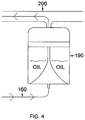
- FIG. 4 is perspective view of oil atomizer
- FIG. 1 in accordance with one or more embodiments of the present invention shows the exterior of assembled unit 110 being the chamber, 140 being the right removable end cap, 120 being the oil less air compressor connected to 160 the inlet air tube that delivers air to the inside of the chamber, 170 being the exhaust air line from chamber 110 to 130 the inline air filter. 110 , 120 , and 130 attached to base 180 .
- FIG. 2 in accordance with one or more embodiments of the present of the present invention shows the end of unit chamber 110 without end cap 140 .
- air runs through in let air tube 160 into oil atomizer 190 allowing oil to vapor through oil vapor delivery tube 200 directing vapor into chamber 110 .
- FIG. 3 in accordance with one or more embodiments of the present invention shows 120 pump on with air going into 160 air tube to 190 oil atomizer directing oil vapor into 200 delivery line to chamber 110 .
- Chamber closed at both ends by 140 and 150 sealed end caps. Excess vapor exiting through line 170 and 130 filter.
- FIG. 4 in accordance with one or more embodiments of the present invention shows 190 oil atomizer positioned between 160 inlet line and 200 delivery line.
- oil atomizer to be used 1 ounce of oil is added to atomizer approximately every third usage.
- Air filter is attached to base with two open faced spring clamps that are screwed in place through bottom of base. Rubber tubing is attached to air compressor with a barbed fitting and secured in place with a spring clamp, this tubing is then run through side of chamber through sealed hole and attached to oil atomizer with formed rubber elbow and a spring clamp. Oil atomizer is attached to side wall of chamber with a stationary bracket. Chamber delivery tube is attached to oil atomizer with a plastic elbow with barbed end, Chamber exhaust tube is inserted through side wall of chamber at opposite end of chamber from intake tube and run to filter being attached to filter with a slide lock clamp built into filter.
Landscapes
- Engineering & Computer Science (AREA)
- General Engineering & Computer Science (AREA)
- Chemical & Material Sciences (AREA)
- Combustion & Propulsion (AREA)
- Oil, Petroleum & Natural Gas (AREA)
- Mechanical Engineering (AREA)
- Filtering Of Dispersed Particles In Gases (AREA)
- Compressor (AREA)
Abstract
Description
Claims (3)
Priority Applications (1)
| Application Number | Priority Date | Filing Date | Title |
|---|---|---|---|
| US15/732,722 US10557679B2 (en) | 2016-12-22 | 2017-12-20 | Fire alarm and tool oiling system |
Applications Claiming Priority (2)
| Application Number | Priority Date | Filing Date | Title |
|---|---|---|---|
| US201662438047P | 2016-12-22 | 2016-12-22 | |
| US15/732,722 US10557679B2 (en) | 2016-12-22 | 2017-12-20 | Fire alarm and tool oiling system |
Publications (2)
| Publication Number | Publication Date |
|---|---|
| US20180195827A1 US20180195827A1 (en) | 2018-07-12 |
| US10557679B2 true US10557679B2 (en) | 2020-02-11 |
Family
ID=62782755
Family Applications (1)
| Application Number | Title | Priority Date | Filing Date |
|---|---|---|---|
| US15/732,722 Active 2038-08-16 US10557679B2 (en) | 2016-12-22 | 2017-12-20 | Fire alarm and tool oiling system |
Country Status (1)
| Country | Link |
|---|---|
| US (1) | US10557679B2 (en) |
Families Citing this family (1)
| Publication number | Priority date | Publication date | Assignee | Title |
|---|---|---|---|---|
| CN116697243B (en) * | 2023-05-15 | 2025-10-28 | 安徽百通达科技医疗用品有限公司 | Automatic lubrication device for mold base |
Citations (7)
| Publication number | Priority date | Publication date | Assignee | Title |
|---|---|---|---|---|
| US3736902A (en) * | 1970-10-19 | 1973-06-05 | Voest Ag | Apparatus for oiling sheet metal stock |
| US4089295A (en) * | 1976-02-02 | 1978-05-16 | Madison-Kipp Corporation | Spray coater device |
| US4724155A (en) * | 1984-12-14 | 1988-02-09 | Weirton Steel Corporation | Lubrication of cup-shaped can bodies |
| JPH06106270A (en) * | 1992-09-25 | 1994-04-19 | Sanwa Buhin Kogyo Kk | Machining oil dispersing device |
| US20060278256A1 (en) * | 2005-06-11 | 2006-12-14 | Robert Biddy | Apparatus for treating a firearm |
| US8356696B1 (en) * | 2009-06-12 | 2013-01-22 | Honda Motor Co., Ltd. | Air-operated device and method for lubricating components with elimination of lubricant waste |
| US20160184844A1 (en) * | 2013-08-13 | 2016-06-30 | Sames Technologies | Atomizer for a lubricant product and lubrication system comprising said atomizer |
-
2017
- 2017-12-20 US US15/732,722 patent/US10557679B2/en active Active
Patent Citations (7)
| Publication number | Priority date | Publication date | Assignee | Title |
|---|---|---|---|---|
| US3736902A (en) * | 1970-10-19 | 1973-06-05 | Voest Ag | Apparatus for oiling sheet metal stock |
| US4089295A (en) * | 1976-02-02 | 1978-05-16 | Madison-Kipp Corporation | Spray coater device |
| US4724155A (en) * | 1984-12-14 | 1988-02-09 | Weirton Steel Corporation | Lubrication of cup-shaped can bodies |
| JPH06106270A (en) * | 1992-09-25 | 1994-04-19 | Sanwa Buhin Kogyo Kk | Machining oil dispersing device |
| US20060278256A1 (en) * | 2005-06-11 | 2006-12-14 | Robert Biddy | Apparatus for treating a firearm |
| US8356696B1 (en) * | 2009-06-12 | 2013-01-22 | Honda Motor Co., Ltd. | Air-operated device and method for lubricating components with elimination of lubricant waste |
| US20160184844A1 (en) * | 2013-08-13 | 2016-06-30 | Sames Technologies | Atomizer for a lubricant product and lubrication system comprising said atomizer |
Also Published As
| Publication number | Publication date |
|---|---|
| US20180195827A1 (en) | 2018-07-12 |
Similar Documents
| Publication | Publication Date | Title |
|---|---|---|
| US8727233B2 (en) | Pressure spray washer and control | |
| US8800966B2 (en) | Drain plug | |
| CN105188953A (en) | Paint can adapter for handheld spray device | |
| JP2006503706A5 (en) | ||
| CA2593875A1 (en) | Drain cleaning apparatus | |
| US10557679B2 (en) | Fire alarm and tool oiling system | |
| US20180311710A1 (en) | Self-cleaning water pipe | |
| US20180195473A1 (en) | Advanced internal combustion engine air induction cleaning system and method | |
| US9517552B2 (en) | Filter remover | |
| WO2005067501A3 (en) | Container cleaning device | |
| KR101536699B1 (en) | A cleaning machine for engine of vehicle | |
| JP2014522297A (en) | Safe portable nebulizer | |
| KR20210005535A (en) | Paint splash prevention cover housing assembly for spray gun | |
| ATE435705T1 (en) | SPRAY GUN WITH ADAPTED STORAGE CONTAINER | |
| US9638239B2 (en) | Cable lubrication device | |
| KR20110115628A (en) | Paint spreading prevention device | |
| US20150258587A1 (en) | System and method for deep cleaning water ionizers | |
| WO2007009651A3 (en) | Spraying device, method for the production thereof, and use thereof | |
| FR2527480A1 (en) | MANUAL GUN WITH LOW PRESSURE PAINT FOR INDUSTRIAL USE | |
| CN205926102U (en) | Atomizer with reflux unit | |
| MX2017017017A (en) | Accessory for sanitation facilities. | |
| US6824072B2 (en) | Spray gun cleaner | |
| CN215696551U (en) | Vacuum coating machine suitable for computer accessories | |
| EP3205856A1 (en) | Advanced internal combustion engine air induction cleaning system and method | |
| RU139210U1 (en) | SPRAY INSTALLATION OF ANTI-FREEZING COMPONENT |
Legal Events
| Date | Code | Title | Description |
|---|---|---|---|
| FEPP | Fee payment procedure |
Free format text: ENTITY STATUS SET TO MICRO (ORIGINAL EVENT CODE: MICR); ENTITY STATUS OF PATENT OWNER: MICROENTITY |
|
| STPP | Information on status: patent application and granting procedure in general |
Free format text: DOCKETED NEW CASE - READY FOR EXAMINATION |
|
| STPP | Information on status: patent application and granting procedure in general |
Free format text: NOTICE OF ALLOWANCE MAILED -- APPLICATION RECEIVED IN OFFICE OF PUBLICATIONS |
|
| STPP | Information on status: patent application and granting procedure in general |
Free format text: PUBLICATIONS -- ISSUE FEE PAYMENT RECEIVED |
|
| STCF | Information on status: patent grant |
Free format text: PATENTED CASE |
|
| CC | Certificate of correction | ||
| MAFP | Maintenance fee payment |
Free format text: PAYMENT OF MAINTENANCE FEE, 4TH YEAR, MICRO ENTITY (ORIGINAL EVENT CODE: M3551); ENTITY STATUS OF PATENT OWNER: MICROENTITY Year of fee payment: 4 |