US1055152A - Valve-operating device. - Google Patents
Valve-operating device. Download PDFInfo
- Publication number
- US1055152A US1055152A US67862412A US1912678624A US1055152A US 1055152 A US1055152 A US 1055152A US 67862412 A US67862412 A US 67862412A US 1912678624 A US1912678624 A US 1912678624A US 1055152 A US1055152 A US 1055152A
- Authority
- US
- United States
- Prior art keywords
- valve
- lever
- standard
- operating device
- cross head
- Prior art date
- Legal status (The legal status is an assumption and is not a legal conclusion. Google has not performed a legal analysis and makes no representation as to the accuracy of the status listed.)
- Expired - Lifetime
Links
Images
Classifications
-
- H—ELECTRICITY
- H01—ELECTRIC ELEMENTS
- H01H—ELECTRIC SWITCHES; RELAYS; SELECTORS; EMERGENCY PROTECTIVE DEVICES
- H01H21/00—Switches operated by an operating part in the form of a pivotable member acted upon directly by a solid body, e.g. by a hand
- H01H21/02—Details
- H01H21/18—Movable parts; Contacts mounted thereon
- H01H21/22—Operating parts, e.g. handle
- H01H21/24—Operating parts, e.g. handle biased to return to normal position upon removal of operating force
- H01H21/28—Operating parts, e.g. handle biased to return to normal position upon removal of operating force adapted for actuation at a limit or other predetermined position in the path of a body, the relative movement of switch and body being primarily for a purpose other than the actuation of the switch, e.g. door switch, limit switch, floor-levelling switch of a lift
- H01H21/285—Operating parts, e.g. handle biased to return to normal position upon removal of operating force adapted for actuation at a limit or other predetermined position in the path of a body, the relative movement of switch and body being primarily for a purpose other than the actuation of the switch, e.g. door switch, limit switch, floor-levelling switch of a lift having an operating arm actuated by the movement of the body and mounted on an axis converting its rotating movement into a rectilinear switch activating movement
-
- Y—GENERAL TAGGING OF NEW TECHNOLOGICAL DEVELOPMENTS; GENERAL TAGGING OF CROSS-SECTIONAL TECHNOLOGIES SPANNING OVER SEVERAL SECTIONS OF THE IPC; TECHNICAL SUBJECTS COVERED BY FORMER USPC CROSS-REFERENCE ART COLLECTIONS [XRACs] AND DIGESTS
- Y10—TECHNICAL SUBJECTS COVERED BY FORMER USPC
- Y10T—TECHNICAL SUBJECTS COVERED BY FORMER US CLASSIFICATION
- Y10T74/00—Machine element or mechanism
- Y10T74/18—Mechanical movements
- Y10T74/18888—Reciprocating to or from oscillating
- Y10T74/1892—Lever and slide
- Y10T74/1896—Cam connections
Definitions
- My invention has for its object to provide an extremely simple and highly ellicient valve actuating device especially adapted for use to open and close the valves of steam and hot water radiators, but adapted, never thelcss, for more general use.
- the invention consists of the novel devices and combinations of devices hereinafter described and detined in the claims.
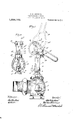
- Figure l a view in side elevation with some parts broken away, showing the improved valve operating device applied to a valve such as used in connection with hot water and steam radiators; and Fig. 2 is a rear elevation of the valve operating; device, some parts being broken away.
- the numeral 1 indicates the casing" amt the numeral 2 the valve head of the said socalled radiator valve. ⁇ Vhcn the valve is closed, the valve head. 2 is seated on a llang'e 3 of the casing, 1.
- the valve head 2 is provided with a long upwardly projecting stem 4 that works through a suitable stalling box 5 on the top of the valve easing 1.
- the valve casing 1 is provided with an upwardly projecting threaded sleeve (3 through which the stem 4 is arranged to move vertically,
- valve mechanism so far described, is or may be assumed to be of ordinary well known construction, such as usually found in connection with radiator valves.
- My improved valve justifyinp; athuzhment comprises a yoke-like standard 7 mato up of laterally spaced legs integrrlly connected at their lower ends, but formed with -'-laniping prongs 8 and with a threaded seat that directly engages the threaded sleeve 6 of the Specification of Letters Patent.
- valve casing 1 A machine screw 9, applied to the prongs 8, serves to rigidly but adjustably clamp the standard onto the said threaded sleeve (3.
- the legs of the standard 7 are parallel and atlord a vertical guide for a cross head 10 to which the threaded upper end of the valve.
- stem 4 is rigidly but adjustably secured.
- the cross head 10 is provided with laterally upwardly projecting cars 12 throu b 7 which a short spindle 13 is passed.
- n anti-friction roller '14 is jaurnaled on the spindle 13 between the ca s 12.
- a valve actuatinglever 15 is pivotally connected by a bolt '1 6 to the extreme upper ends at the legs of the standard 7.
- This lever 15 is of special arwlpeculim' construction, being formed by an endless metal band, the free end portion of which is bent to form a handle, and the main body portion of which is 01 circular form, the lower curve of which extends eccentric and opproximately on the line of involutc curve 15" from the hub '15 of the said lever 15.
- the upper portion of said lever 15, adja cent to its hub, is formed with a reinforced!
- roller 13 is brought so near to the pivot 16 that friction will hold the said valve and lever in their uppermost positions.
- the looped body portion of the lever 15 may be sprung! so that its curved eccentric portion 15 will be adjusted accurately for "forcing the valve head 2 against theseat 3.
- the stiffening rib 17 prevents springing of the lever between its pivot 16 and shoulder 18 end causes all of the spring or edjnstxnent produced in the lever by the adjusting screw 19 to take place in the opposite or lower portion of the said lever.
- the required ad- .lllSiZment of the lever attachment in respect fllii16 valve seat 3 may be nttained'hy rototing the standard 7 on the threaded sleeve Also by rotating the said standard on the said threaded sleeve, the lever may be turned to either side or to any desired position. Then when the screw 9 is tightened,
- the said standard will be securely locked to the said threaded sleeve.
- lhe valve; operating attachment, above described may be easily applied to standard radiator valves and the like, and affords means for very quickly and easily opening or closing the said valve et'will.
- the lever may be moved either to open or close the valve by a simple engagement of the vfoot therewith.
- a valve operating device comprising fixed laterally spiced guides, e cross head movable on said guides and having 2. pair of spsced'ehutments, e valve stem connected instance to said cross need, and a lever pivoted to said guides and having a looped eccentric portion working between and operative on both. of the sbnt nents of said cross head.
- a valve operating device comprising a standard, a cross head movable on said. standard, 21 valve stem connected to said cross head, and a lover pivoted to said standard and having a. looped resilient e0 centric portion operative "on said cross heed.
- valve operating device comprising n standard, a cross head movable on said standard, :1 cross ll'llfld, and a lever pivoted to said standard and having a looped eccentric portion operative on. said cross head, the said lever having means applied thereto for springing and thereby adjusting the looped eccentric portion there-of.
- a valve operating device comprising a standard, a cross heed movable on the said standard, a valve stem connected to said cross head, and a. lever pivoted to said standard and having a looped eccentric portion operative on said cross head, the said lever having mes-ins applied thereto for springing and thereby adjusting the looped eccentric portion thereof and the said cross head having a portion working in the loop of said lever in close engagement with the eccentric portion thereof, whereby said cross head will be positively moved in both directions by said lever.
Description
'. 0. H. BRIGKSON.
VALVE OPERATING DEVICE.
APPLICATION FILED FBB.19,1912.
r'na
tJTTO H. ERICKSON, OF MINNEAPOLIS, MINNESOTA.
VALVE-OPERATING DEVICE.
App ication filed February 19, 1912.
To HUNT/[.0111 1'15 may concur/1.
Be it known that I, O'r'ro ll. llltltKSUN, a citizen ot the ,lnited States. residing at Minneapolis, in the county of lleuncpin and State of hlinnesota, have invented certain new and useful improvements in Valve-Opcrating- Devices; and l do hereby declare the following to be a full, clear, and exact description of the invention, such as will enable others skilled in the art to which it appertains to make and use the same,
My invention has for its object to provide an extremely simple and highly ellicient valve actuating device especially adapted for use to open and close the valves of steam and hot water radiators, but adapted, never thelcss, for more general use.
.Gcnerally stated, the invention consists of the novel devices and combinations of devices hereinafter described and detined in the claims.
The invention is illustrated in the accompanying drawings wherein like characters indicate like parts tl'ironghoul the several views.
. Referring to the drawings, Figure l. a view in side elevation with some parts broken away, showing the improved valve operating device applied to a valve such as used in connection with hot water and steam radiators; and Fig. 2 is a rear elevation of the valve operating; device, some parts being broken away.
The numeral 1 indicates the casing" amt the numeral 2 the valve head of the said socalled radiator valve. \Vhcn the valve is closed, the valve head. 2 is seated on a llang'e 3 of the casing, 1. The valve head 2 is provided with a long upwardly projecting stem 4 that works through a suitable stalling box 5 on the top of the valve easing 1. The valve casing 1 is provided with an upwardly projecting threaded sleeve (3 through which the stem 4 is arranged to move vertically,
and to the upper end of which the shilling box is shown as applied.
The valve mechanism, so far described, is or may be assumed to be of ordinary well known construction, such as usually found in connection with radiator valves.
My improved valve luatinp; athuzhment comprises a yoke-like standard 7 mato up of laterally spaced legs integrrlly connected at their lower ends, but formed with -'-laniping prongs 8 and with a threaded seat that directly engages the threaded sleeve 6 of the Specification of Letters Patent.
Patented Mar. 4,1 913.
Serial No. 678,624.
valve casing 1. A machine screw 9, applied to the prongs 8, serves to rigidly but adjustably clamp the standard onto the said threaded sleeve (3. the legs of the standard 7 are parallel and atlord a vertical guide for a cross head 10 to which the threaded upper end of the valve. stem 4 is rigidly but adjustably secured.
'lhe till'ttflt'litT Qlld of the stem 4 is preferably 5 screwed into the depending lmb of the cross head '10 and is locked thereto by a jam nut 11. Just inside of the legs of the standard 7, the cross head 10 is provided with laterally upwardly projecting cars 12 throu b 7 which a short spindle 13 is passed. n anti-friction roller '14 is jaurnaled on the spindle 13 between the ca s 12. The sides of the ss head '10, as will be noted, are
grooved to receive the parallel upper por- 5 tions of the legs of the standard 7.
A valve actuatinglever 15 is pivotally connected by a bolt '1 6 to the extreme upper ends at the legs of the standard 7. This lever 15 is of special arwlpeculim' construction, being formed by an endless metal band, the free end portion of which is bent to form a handle, and the main body portion of which is 01 circular form, the lower curve of which extends eccentric and opproximately on the line of involutc curve 15" from the hub '15 of the said lever 15. The upper portion of said lever 15, adja cent to its hub, is formed with a reinforced! or stitl'cnine rib 17, just out of which is a shoulder or bearing surl'ace 15% that is 'ngaged by the end of an adjusting screw 19 which works with screw threaded arrangement through the opposite side of tlnv said lever, and is preferably normally locl cd by a jam nut 520. The eccentric portion 15 ot said lever 15 works in the space between the roller 14- and the top of the central portion of the cross head 10, and is engagcablc with the former when the lever is raised,
and with the latter when the lever isforced downward When the lever is forced downward, it tightly closes the valve head 2 against its seat 3, but when the said lever is raised, it positively raises the said valve stands so near to a dead center in respect to the pivot 16 that friction betwcen'thc said lever and cross head will lock the said lever The upper portions of 6|) (FIT) and the said valve in their downwardly pressed positions. Also when the lever is v raised, as shown by dotted lines in Fig. l,
the roller 13 is brought so near to the pivot 16 that friction will hold the said valve and lever in their uppermost positions.
By adjustments of the screw 19,the looped body portion of the lever 15 may be sprung! so that its curved eccentric portion 15 will be adjusted accurately for "forcing the valve head 2 against theseat 3. The stiffening rib 17 prevents springing of the lever between its pivot 16 and shoulder 18 end causes all of the spring or edjnstxnent produced in the lever by the adjusting screw 19 to take place in the opposite or lower portion of the said lever. Approximately, the required ad- .lllSiZment of the lever attachment in respect fllii16 valve seat 3 may be nttained'hy rototing the standard 7 on the threaded sleeve Also by rotating the said standard on the said threaded sleeve, the lever may be turned to either side or to any desired position. Then when the screw 9 is tightened,
the said standard will be securely locked to the said threaded sleeve.
lhe valve; operating attachment, above described, may be easily applied to standard radiator valves and the like, and affords means for very quickly and easily opening or closing the said valve et'will. In fact, the lever may be moved either to open or close the valve by a simple engagement of the vfoot therewith.
1. A valve operating device, comprising fixed laterally spiced guides, e cross head movable on said guides and having 2. pair of spsced'ehutments, e valve stem connected instance to said cross need, and a lever pivoted to said guides and having a looped eccentric portion working between and operative on both. of the sbnt nents of said cross head.
2. A valve operating device comprising a standard, a cross head movable on said. standard, 21 valve stem connected to said cross head, and a lover pivoted to said standard and having a. looped resilient e0 centric portion operative "on said cross heed. valve operating device comprising n standard, a cross head movable on said standard, :1 cross ll'llfld, and a lever pivoted to said standard and having a looped eccentric portion operative on. said cross head, the said lever having means applied thereto for springing and thereby adjusting the looped eccentric portion there-of.-
4. A valve operating device comprising a standard, a cross heed movable on the said standard, a valve stem connected to said cross head, and a. lever pivoted to said standard and having a looped eccentric portion operative on said cross head, the said lever having mes-ins applied thereto for springing and thereby adjusting the looped eccentric portion thereof and the said cross head having a portion working in the loop of said lever in close engagement with the eccentric portion thereof, whereby said cross head will be positively moved in both directions by said lever.
In testimony whereof I afi'ix my signs. ture in presence of two witnesses.
@TTG ERICKSON. i v'itnesses:
Henna D. KILcoRE, lb. D. MERCHANT.
valve stem connected to said
Priority Applications (1)
| Application Number | Priority Date | Filing Date | Title |
|---|---|---|---|
| US67862412A US1055152A (en) | 1912-02-19 | 1912-02-19 | Valve-operating device. |
Applications Claiming Priority (1)
| Application Number | Priority Date | Filing Date | Title |
|---|---|---|---|
| US67862412A US1055152A (en) | 1912-02-19 | 1912-02-19 | Valve-operating device. |
Publications (1)
| Publication Number | Publication Date |
|---|---|
| US1055152A true US1055152A (en) | 1913-03-04 |
Family
ID=3123411
Family Applications (1)
| Application Number | Title | Priority Date | Filing Date |
|---|---|---|---|
| US67862412A Expired - Lifetime US1055152A (en) | 1912-02-19 | 1912-02-19 | Valve-operating device. |
Country Status (1)
| Country | Link |
|---|---|
| US (1) | US1055152A (en) |
Cited By (6)
| Publication number | Priority date | Publication date | Assignee | Title |
|---|---|---|---|---|
| US2543205A (en) * | 1948-08-06 | 1951-02-27 | Willie M Shoffner | Cam actuator and lock |
| US2732166A (en) * | 1956-01-24 | Dual action valve | ||
| US2774565A (en) * | 1951-03-13 | 1956-12-18 | Vaillant Joh Kg | Valve for gas water heaters |
| US2905433A (en) * | 1956-11-13 | 1959-09-22 | Crane Co | Adjustable valve actuation means |
| US2997063A (en) * | 1957-05-06 | 1961-08-22 | Anderson Brass Co | Valve |
| US4782856A (en) * | 1987-04-15 | 1988-11-08 | Gordon-Piatt Energy Group, Inc. | Modulating flow control valve |
-
1912
- 1912-02-19 US US67862412A patent/US1055152A/en not_active Expired - Lifetime
Cited By (6)
| Publication number | Priority date | Publication date | Assignee | Title |
|---|---|---|---|---|
| US2732166A (en) * | 1956-01-24 | Dual action valve | ||
| US2543205A (en) * | 1948-08-06 | 1951-02-27 | Willie M Shoffner | Cam actuator and lock |
| US2774565A (en) * | 1951-03-13 | 1956-12-18 | Vaillant Joh Kg | Valve for gas water heaters |
| US2905433A (en) * | 1956-11-13 | 1959-09-22 | Crane Co | Adjustable valve actuation means |
| US2997063A (en) * | 1957-05-06 | 1961-08-22 | Anderson Brass Co | Valve |
| US4782856A (en) * | 1987-04-15 | 1988-11-08 | Gordon-Piatt Energy Group, Inc. | Modulating flow control valve |
Similar Documents
| Publication | Publication Date | Title |
|---|---|---|
| US1055152A (en) | Valve-operating device. | |
| US1580499A (en) | Valve-control mechanism | |
| US308186A (en) | Timothy mohugh | |
| US1113282A (en) | Emergency check-valve. | |
| US423240A (en) | Valve-operating mechanism | |
| US644224A (en) | Elbow-lever valve. | |
| US1250023A (en) | Control apparatus for siphons. | |
| US1145703A (en) | Valve. | |
| US299669A (en) | Haeey c | |
| US265239A (en) | Automatic air-cock for steam-heat radiators | |
| US1092482A (en) | Valve. | |
| US752818A (en) | Gas-valve lock | |
| US349941A (en) | Joseph keoupa | |
| US970082A (en) | Faucet. | |
| US1064640A (en) | Valve-spring lifter. | |
| US541783A (en) | Door-check | |
| US1130063A (en) | Line-stretcher. | |
| US496045A (en) | Self-closing valve | |
| US539631A (en) | James morrison- | |
| US544727A (en) | Basin-faucet | |
| US612268A (en) | Patrick k | |
| US1336202A (en) | Valve-lifter | |
| US1246537A (en) | Safety gas-valve. | |
| US963305A (en) | Float-valve. | |
| US931701A (en) | Door-closure. |