US10550881B2 - Axle and bearing for conveyor chain link - Google Patents
Axle and bearing for conveyor chain link Download PDFInfo
- Publication number
- US10550881B2 US10550881B2 US15/660,123 US201715660123A US10550881B2 US 10550881 B2 US10550881 B2 US 10550881B2 US 201715660123 A US201715660123 A US 201715660123A US 10550881 B2 US10550881 B2 US 10550881B2
- Authority
- US
- United States
- Prior art keywords
- axle pin
- roller bearing
- conveyor chain
- link
- bearing wheel
- Prior art date
- Legal status (The legal status is an assumption and is not a legal conclusion. Google has not performed a legal analysis and makes no representation as to the accuracy of the status listed.)
- Active
Links
- 239000000463 material Substances 0.000 description 5
- 238000009987 spinning Methods 0.000 description 5
- 229910000831 Steel Inorganic materials 0.000 description 3
- 238000004519 manufacturing process Methods 0.000 description 3
- 239000007769 metal material Substances 0.000 description 3
- 238000000034 method Methods 0.000 description 3
- 239000010959 steel Substances 0.000 description 3
- HCHKCACWOHOZIP-UHFFFAOYSA-N Zinc Chemical compound [Zn] HCHKCACWOHOZIP-UHFFFAOYSA-N 0.000 description 2
- 230000008901 benefit Effects 0.000 description 2
- 230000008602 contraction Effects 0.000 description 2
- 230000001788 irregular Effects 0.000 description 2
- 239000002184 metal Substances 0.000 description 2
- 229910052751 metal Inorganic materials 0.000 description 2
- 230000002093 peripheral effect Effects 0.000 description 2
- 229910052725 zinc Inorganic materials 0.000 description 2
- 239000011701 zinc Substances 0.000 description 2
- 238000007792 addition Methods 0.000 description 1
- 235000015173 baked goods and baking mixes Nutrition 0.000 description 1
- 238000012217 deletion Methods 0.000 description 1
- 230000037430 deletion Effects 0.000 description 1
- 230000006698 induction Effects 0.000 description 1
- 238000010329 laser etching Methods 0.000 description 1
- 238000012423 maintenance Methods 0.000 description 1
- 238000012986 modification Methods 0.000 description 1
- 230000004048 modification Effects 0.000 description 1
- 239000000843 powder Substances 0.000 description 1
- 230000000717 retained effect Effects 0.000 description 1
Images


Classifications
-
- F—MECHANICAL ENGINEERING; LIGHTING; HEATING; WEAPONS; BLASTING
- F16—ENGINEERING ELEMENTS AND UNITS; GENERAL MEASURES FOR PRODUCING AND MAINTAINING EFFECTIVE FUNCTIONING OF MACHINES OR INSTALLATIONS; THERMAL INSULATION IN GENERAL
- F16C—SHAFTS; FLEXIBLE SHAFTS; ELEMENTS OR CRANKSHAFT MECHANISMS; ROTARY BODIES OTHER THAN GEARING ELEMENTS; BEARINGS
- F16C19/00—Bearings with rolling contact, for exclusively rotary movement
- F16C19/02—Bearings with rolling contact, for exclusively rotary movement with bearing balls essentially of the same size in one or more circular rows
- F16C19/10—Bearings with rolling contact, for exclusively rotary movement with bearing balls essentially of the same size in one or more circular rows for axial load mainly
-
- B—PERFORMING OPERATIONS; TRANSPORTING
- B21—MECHANICAL METAL-WORKING WITHOUT ESSENTIALLY REMOVING MATERIAL; PUNCHING METAL
- B21K—MAKING FORGED OR PRESSED METAL PRODUCTS, e.g. HORSE-SHOES, RIVETS, BOLTS OR WHEELS
- B21K25/00—Uniting components to form integral members, e.g. turbine wheels and shafts, caulks with inserts, with or without shaping of the components
-
- B—PERFORMING OPERATIONS; TRANSPORTING
- B65—CONVEYING; PACKING; STORING; HANDLING THIN OR FILAMENTARY MATERIAL
- B65G—TRANSPORT OR STORAGE DEVICES, e.g. CONVEYORS FOR LOADING OR TIPPING, SHOP CONVEYOR SYSTEMS OR PNEUMATIC TUBE CONVEYORS
- B65G17/00—Conveyors having an endless traction element, e.g. a chain, transmitting movement to a continuous or substantially-continuous load-carrying surface or to a series of individual load-carriers; Endless-chain conveyors in which the chains form the load-carrying surface
- B65G17/30—Details; Auxiliary devices
- B65G17/32—Individual load-carriers
-
- B—PERFORMING OPERATIONS; TRANSPORTING
- B65—CONVEYING; PACKING; STORING; HANDLING THIN OR FILAMENTARY MATERIAL
- B65G—TRANSPORT OR STORAGE DEVICES, e.g. CONVEYORS FOR LOADING OR TIPPING, SHOP CONVEYOR SYSTEMS OR PNEUMATIC TUBE CONVEYORS
- B65G17/00—Conveyors having an endless traction element, e.g. a chain, transmitting movement to a continuous or substantially-continuous load-carrying surface or to a series of individual load-carriers; Endless-chain conveyors in which the chains form the load-carrying surface
- B65G17/30—Details; Auxiliary devices
- B65G17/38—Chains or like traction elements; Connections between traction elements and load-carriers
- B65G17/40—Chains acting as load-carriers
-
- B—PERFORMING OPERATIONS; TRANSPORTING
- B65—CONVEYING; PACKING; STORING; HANDLING THIN OR FILAMENTARY MATERIAL
- B65G—TRANSPORT OR STORAGE DEVICES, e.g. CONVEYORS FOR LOADING OR TIPPING, SHOP CONVEYOR SYSTEMS OR PNEUMATIC TUBE CONVEYORS
- B65G39/00—Rollers, e.g. drive rollers, or arrangements thereof incorporated in roller-ways or other types of mechanical conveyors
- B65G39/10—Arrangements of rollers
- B65G39/20—Arrangements of rollers attached to moving belts or chains
-
- F—MECHANICAL ENGINEERING; LIGHTING; HEATING; WEAPONS; BLASTING
- F16—ENGINEERING ELEMENTS AND UNITS; GENERAL MEASURES FOR PRODUCING AND MAINTAINING EFFECTIVE FUNCTIONING OF MACHINES OR INSTALLATIONS; THERMAL INSULATION IN GENERAL
- F16C—SHAFTS; FLEXIBLE SHAFTS; ELEMENTS OR CRANKSHAFT MECHANISMS; ROTARY BODIES OTHER THAN GEARING ELEMENTS; BEARINGS
- F16C13/00—Rolls, drums, discs, or the like; Bearings or mountings therefor
- F16C13/006—Guiding rollers, wheels or the like, formed by or on the outer element of a single bearing or bearing unit, e.g. two adjacent bearings, whose ratio of length to diameter is generally less than one
-
- F—MECHANICAL ENGINEERING; LIGHTING; HEATING; WEAPONS; BLASTING
- F16—ENGINEERING ELEMENTS AND UNITS; GENERAL MEASURES FOR PRODUCING AND MAINTAINING EFFECTIVE FUNCTIONING OF MACHINES OR INSTALLATIONS; THERMAL INSULATION IN GENERAL
- F16C—SHAFTS; FLEXIBLE SHAFTS; ELEMENTS OR CRANKSHAFT MECHANISMS; ROTARY BODIES OTHER THAN GEARING ELEMENTS; BEARINGS
- F16C19/00—Bearings with rolling contact, for exclusively rotary movement
- F16C19/02—Bearings with rolling contact, for exclusively rotary movement with bearing balls essentially of the same size in one or more circular rows
- F16C19/04—Bearings with rolling contact, for exclusively rotary movement with bearing balls essentially of the same size in one or more circular rows for radial load mainly
- F16C19/06—Bearings with rolling contact, for exclusively rotary movement with bearing balls essentially of the same size in one or more circular rows for radial load mainly with a single row or balls
-
- F—MECHANICAL ENGINEERING; LIGHTING; HEATING; WEAPONS; BLASTING
- F16—ENGINEERING ELEMENTS AND UNITS; GENERAL MEASURES FOR PRODUCING AND MAINTAINING EFFECTIVE FUNCTIONING OF MACHINES OR INSTALLATIONS; THERMAL INSULATION IN GENERAL
- F16C—SHAFTS; FLEXIBLE SHAFTS; ELEMENTS OR CRANKSHAFT MECHANISMS; ROTARY BODIES OTHER THAN GEARING ELEMENTS; BEARINGS
- F16C33/00—Parts of bearings; Special methods for making bearings or parts thereof
- F16C33/30—Parts of ball or roller bearings
- F16C33/32—Balls
-
- F—MECHANICAL ENGINEERING; LIGHTING; HEATING; WEAPONS; BLASTING
- F16—ENGINEERING ELEMENTS AND UNITS; GENERAL MEASURES FOR PRODUCING AND MAINTAINING EFFECTIVE FUNCTIONING OF MACHINES OR INSTALLATIONS; THERMAL INSULATION IN GENERAL
- F16C—SHAFTS; FLEXIBLE SHAFTS; ELEMENTS OR CRANKSHAFT MECHANISMS; ROTARY BODIES OTHER THAN GEARING ELEMENTS; BEARINGS
- F16C33/00—Parts of bearings; Special methods for making bearings or parts thereof
- F16C33/30—Parts of ball or roller bearings
- F16C33/34—Rollers; Needles
-
- F—MECHANICAL ENGINEERING; LIGHTING; HEATING; WEAPONS; BLASTING
- F16—ENGINEERING ELEMENTS AND UNITS; GENERAL MEASURES FOR PRODUCING AND MAINTAINING EFFECTIVE FUNCTIONING OF MACHINES OR INSTALLATIONS; THERMAL INSULATION IN GENERAL
- F16C—SHAFTS; FLEXIBLE SHAFTS; ELEMENTS OR CRANKSHAFT MECHANISMS; ROTARY BODIES OTHER THAN GEARING ELEMENTS; BEARINGS
- F16C33/00—Parts of bearings; Special methods for making bearings or parts thereof
- F16C33/30—Parts of ball or roller bearings
- F16C33/58—Raceways; Race rings
- F16C33/583—Details of specific parts of races
- F16C33/586—Details of specific parts of races outside the space between the races, e.g. end faces or bore of inner ring
-
- F—MECHANICAL ENGINEERING; LIGHTING; HEATING; WEAPONS; BLASTING
- F16—ENGINEERING ELEMENTS AND UNITS; GENERAL MEASURES FOR PRODUCING AND MAINTAINING EFFECTIVE FUNCTIONING OF MACHINES OR INSTALLATIONS; THERMAL INSULATION IN GENERAL
- F16C—SHAFTS; FLEXIBLE SHAFTS; ELEMENTS OR CRANKSHAFT MECHANISMS; ROTARY BODIES OTHER THAN GEARING ELEMENTS; BEARINGS
- F16C35/00—Rigid support of bearing units; Housings, e.g. caps, covers
- F16C35/04—Rigid support of bearing units; Housings, e.g. caps, covers in the case of ball or roller bearings
- F16C35/06—Mounting or dismounting of ball or roller bearings; Fixing them onto shaft or in housing
- F16C35/063—Fixing them on the shaft
- F16C35/0635—Fixing them on the shaft the bore of the inner ring being of special non-cylindrical shape which co-operates with a complementary shape on the shaft, e.g. teeth, polygonal sections
-
- F—MECHANICAL ENGINEERING; LIGHTING; HEATING; WEAPONS; BLASTING
- F16—ENGINEERING ELEMENTS AND UNITS; GENERAL MEASURES FOR PRODUCING AND MAINTAINING EFFECTIVE FUNCTIONING OF MACHINES OR INSTALLATIONS; THERMAL INSULATION IN GENERAL
- F16G—BELTS, CABLES, OR ROPES, PREDOMINANTLY USED FOR DRIVING PURPOSES; CHAINS; FITTINGS PREDOMINANTLY USED THEREFOR
- F16G13/00—Chains
- F16G13/02—Driving-chains
- F16G13/06—Driving-chains with links connected by parallel driving-pins with or without rollers so called open links
-
- F—MECHANICAL ENGINEERING; LIGHTING; HEATING; WEAPONS; BLASTING
- F16—ENGINEERING ELEMENTS AND UNITS; GENERAL MEASURES FOR PRODUCING AND MAINTAINING EFFECTIVE FUNCTIONING OF MACHINES OR INSTALLATIONS; THERMAL INSULATION IN GENERAL
- F16G—BELTS, CABLES, OR ROPES, PREDOMINANTLY USED FOR DRIVING PURPOSES; CHAINS; FITTINGS PREDOMINANTLY USED THEREFOR
- F16G13/00—Chains
- F16G13/02—Driving-chains
- F16G13/10—Driving-chains with universal joints
-
- F—MECHANICAL ENGINEERING; LIGHTING; HEATING; WEAPONS; BLASTING
- F16—ENGINEERING ELEMENTS AND UNITS; GENERAL MEASURES FOR PRODUCING AND MAINTAINING EFFECTIVE FUNCTIONING OF MACHINES OR INSTALLATIONS; THERMAL INSULATION IN GENERAL
- F16C—SHAFTS; FLEXIBLE SHAFTS; ELEMENTS OR CRANKSHAFT MECHANISMS; ROTARY BODIES OTHER THAN GEARING ELEMENTS; BEARINGS
- F16C2226/00—Joining parts; Fastening; Assembling or mounting parts
- F16C2226/50—Positive connections
- F16C2226/52—Positive connections with plastic deformation, e.g. caulking or staking
-
- F—MECHANICAL ENGINEERING; LIGHTING; HEATING; WEAPONS; BLASTING
- F16—ENGINEERING ELEMENTS AND UNITS; GENERAL MEASURES FOR PRODUCING AND MAINTAINING EFFECTIVE FUNCTIONING OF MACHINES OR INSTALLATIONS; THERMAL INSULATION IN GENERAL
- F16C—SHAFTS; FLEXIBLE SHAFTS; ELEMENTS OR CRANKSHAFT MECHANISMS; ROTARY BODIES OTHER THAN GEARING ELEMENTS; BEARINGS
- F16C2326/00—Articles relating to transporting
- F16C2326/58—Conveyor systems, e.g. rollers or bearings therefor
Definitions
- the present invention relates generally to the field of conveyor equipment for manufacturing, and more particularly to a roller chain axle and bearing assembly for conveyor equipment such as in commercial baking systems, which reduces wear and improves equipment longevity.
- Continuous conveyor systems are utilized in various commercial production equipment systems, such as in oven and proofer systems for commercial bakeries. These conveyor systems commonly include a roller chain that carries baking trays or other conveyed equipment or materials along a track or guide path through various stations of the system.
- Known roller chains may include bearing wheels or rollers coupled by an axle pin to link pieces of the conveyor chain.
- axle pin that holds the single row bearings together through the powder metal linkage pieces of the chain will sometimes spin freely around the inside of the bearing. This spinning may accelerate wear of the equipment, resulting in equipment failures, increased maintenance requirements, and system downtime.
- the present invention provides an axle and bearing for a conveyor chain link that includes anti-spin engagement between the bearing and the axle and includes anti-spin engagement between the axle and the link component.
- the present invention relates to conveyor chain link including a link component, and axle pin, and at least one roller bearing wheel.
- the axle pin includes an elongated generally cylindrical axle pin body having a medial portion and two distal ends.
- the medial portion of the axle pin body has at least one surface engagement feature configured for anti-spin engagement with the link component.
- the at least one roller bearing wheel includes at least one engagement feature configured for anti-spin engagement with one of the distal ends of the axle pin body.
- the invention in another aspect, relates to a method of assembling a conveyor chain link, the method includes positioning two roller bearing wheels on each side of a link component.
- Each roller bearing wheel comprises a central hole and the link component comprises a bore extending through a width of the link component.
- the hole of each roller bearing wheel is positioned to align with the bore of the link component.
- an axle pin having an elongated generally cylindrical axle pin body and two distal ends is push fitted through the holes in the roller bearing wheels and the bore in the link component.
- the axle pin includes a medial portion with at least one surface engagement feature.
- the axle pin is positioned such that the at least one surface engagement feature is at least partially positioned within the bore of the link component and the distal ends of the axle pin extend beyond the holes of the roller bearing wheels.
- the distal ends of the axle pin are deformed to attach the roller bearing wheels to the link component.
- the invention in still another aspect, relates to conveyor chain link including at least one roller bearing wheel, an axle pin, and a link component.
- the roller bearing wheel includes a female receiver opening having a cross-section wherein the female receiver opening cross-section comprises at least one flat surface.
- the axle pin includes first and second axial ends, at least one of the axial ends defining a male engagement profile, wherein the male engagement profile is configured to match the female receiver opening cross-section of the roller bearing wheel.
- the invention relates to a conveyor chain for a commercial baking conveyor comprising a plurality of conveyor chain links coupled to one another to form an elongate assembly allowing relative pivotal movement between adjacent links.
- At least one link comprises a link component, an axle pin, and a roller bearing wheel.
- the link component includes first and second ends, each configured to attach to an adjacent link in the conveyor chain, and a medial section therebetween.
- the medial section includes a bore.
- the axle pin includes first and second axle ends and a medial section therebetween.
- the medial portion comprises at least one surface engagement feature configured for anti-spin engagement with the bore of the link component.
- the at least one roller bearing wheel where an inner circumference of the roller bearing wheel comprises at least one engagement feature configured for anti-spin engagement with one of the first or second axle ends of the axle pin.
- FIG. 1 is a perspective view of a conveyor system including a conveyor chain, to which example embodiments of the present invention can be applied.
- FIG. 2 is a perspective view of a conveyor chain link according to an example embodiment of the invention.
- FIG. 3 is a perspective view of the bearing of the conveyor chain link of FIG. 2 .
- FIG. 4 is a perspective view of the axle pin of the conveyor chain link of FIG. 2 .
- FIG. 5 is a perspective view of the link component of the conveyor chain link of FIG. 2 .
- FIG. 6 is a perspective view of the conveyor chain link of FIG. 2 .
- FIG. 7A is a detailed view of an inner race of the bearing of FIG. 3 .
- FIG. 7B is a detailed view of the inner race of FIG. 7A and an undeformed distal end of an axle pin.
- FIG. 8A is a cutaway view of the conveyor chain link of FIG. 2 .
- FIG. 8B is a cutaway view of the axle pin and bearing race of FIG. 8A .
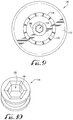
- FIG. 9 is a side view of bearing for a conveyor chain link according to another example embodiment of the present invention.
- FIG. 10 is a perspective view of a portion of the inner race of FIG. 9 .
- FIG. 11 is a perspective view of an axle pin and the bearing race of FIG. 10 .
- FIGS. 1 and 2 show a conveyor system 10 for commercial production of baked goods.
- the conveyor system 10 includes a roller chain 20 that travels through and along a guide track 80 .
- the roller chain 20 may have one or more carrier(s) 82 mounted thereto, for carrying baking trays 84 and/or other conveyed equipment along a conveyor path defined by the guide track 80 .
- the guide track 80 can carry baking trays 84 through a proofer, oven, or other commercial baking equipment.
- the roller chain 20 comprises a plurality of interconnected links 22 pivotally or flexibly coupled to one another, allowing the chain to conform to and follow the conveyor path of the guide track 80 .
- One or more of the links 22 preferably comprise roller-carrier links 24 , to which vertical roller bearing wheels 30 are mounted.
- One or more links 22 can also optionally carry horizontal guide wheels or rollers 26 oriented generally transverse or perpendicular to the vertical roller bearing wheels 30 .
- the roller-carrier links 24 shown in FIGS. 3-6 , generally comprise at least one roller bearing wheel 30 , an axle pin 50 , and a link component 60 .
- the roller carrier link 24 includes two roller bearing wheels 30 .
- the roller bearing wheels 30 are mounted to the link component 60 by the axle pin 50 extending through a bore or channel 62 in the link component.
- a roller bearing wheel 30 according to an example embodiment of the invention is shown in FIG. 3 .
- the roller bearing wheel 30 is generally circular including an outer race 32 having a circular outer circumferential rim and a concentrically located inner race 34 .
- a plurality of ball bearings 36 are retained in an annular space between the inner race 34 and the outer race 32 .
- the roller bearing wheel 30 is generally formed from a metal material, for example standard grade steel.
- the outer race 32 is configured to rotate as it moves along the guide track 80 .
- the inner race 34 is configured to remain generally stationary.
- the inner race 34 includes a front surface 40 and a rear surface 42 with a hole 38 extending through the inner race from the front surface to the back surface.
- the inner diameter or inner circumference of the front face 40 of the inner race 34 includes a chamfer or beveled section 44 extending inward toward the hole 38 .
- the inner race 34 can include an engagement feature 46 configured for anti-spin engagement with the axle pin 50 .
- four groves 46 are provided at approximately 90° intervals about the beveled section 44 of the inner race 34 .
- the grooves 46 are formed by laser etching or otherwise machined into or onto the beveled surface 44 of the inner race 34 .
- the grooves 46 can have, for example, a depth of around 0.015 inches and a width of about 0.100 inches.
- the inner race 34 does not include a beveled section 44 , and the grooves are positioned on the front surface 40 .
- more or fewer grooves 46 can be used.
- the grooves 46 are configured to interact with the axle pin as detailed below.
- other engagement features are used for anti-spin engagement with the axle pin 50 .
- the axle pin 50 generally has an elongated, cylindrical axle pin body having a medial portion 52 and two distal ends 54 .
- the axle pin 50 includes a knurled or ribbed central or medial portion 52 having alternating ridges and grooves extending generally parallel with the lengthwise axis of the pin.
- the ribbed medial portion 52 is configured to create friction between the axle pin 50 and the link component 60 to prevent spinning of the axle pin.
- another pattern can be used on the medial portion 52 to create friction.
- the distal or outer ends 54 of the axle pin 50 are configured to be received within the inner diameter of the inner bearing race 34 of the roller bearing wheel 30 with an interference or press fit.
- the outer ends 54 of the axle pin 50 are preferably flared or riveted down to expand the outer diameter of the ends and cause the material of the axle pin to flow or expand into the groove or grooves 46 in the inner bearing race 34 to attach the roller bearing wheel 30 to the link component 60 . This is intended to lock the axle pin 50 in place within the inner bearing race 34 of the roller bearing wheels 30 and resist or prevent spinning of the axle pin within the inner bearing race 34 .
- the outer diameter of the axle pin 50 is about 0.32 inches and the length is about 1.75 inches.
- the outer diameter and length of the axle pin 50 can optionally be larger or smaller in alternative embodiments.
- the fit between the ends 54 of the axle pin and the hole 38 in the inner race 34 is preferably configured to maintain engagement and resist spinning or relative movement between the engaged surfaces, through an intended range of operating temperatures and thermal expansion and contraction of the equipment.
- the axle pin 50 is generally formed from a metal material, such as standard grade steel.
- the axle pin can also be plated, for example in zinc.
- the medial portion 52 of the axle pin 50 is induction hardened to be a greater hardness than the link component 60 .
- the medial portion 52 of the axle pin 50 is hardened at a depth of around 1/16 th of an inch.
- the medial portion 52 is hardened to have a hardness of around 120 on the Rockwell B Hardness scale. This allows the medial portion 52 to provide “bite” into, or displace the material of, the bore 62 of the link component 60 for a more secure engagement.
- the ends 54 of the axle pin 50 are unhardened allowing the material at the ends of the pin to more freely expand into the engagement feature 46 of the inner race 34 of the roller bearing wheel 30 .
- the ends 54 of the axle pin 50 have a hardness of about 60 on the Rockwell B hardness scale.
- a link component 60 according to an example embodiment of the invention is shown in FIG. 5 .
- the link component 60 generally includes a bore or channel 62 in the medial portion of the link.
- the ends 64 of the link component 60 are configured to attach to the next link 22 in the roller chain.
- the link component 60 includes a first attachment 66 generally parallel to the bore 62 and a second attachment 68 generally perpendicular to the bore.
- the fit between the bore 62 and the medial portion 52 of the axle pin 50 is preferably configured to maintain engagement and resist spinning or relative movement between the engaged surfaces through an intended range of operating temperatures and thermal expansion and contraction of the equipment.
- the link component 60 is generally formed from a metal material, such as standard grade steel.
- the link component can also be plated, for example in zinc.
- the metal has a hardness on the Rockwell B hardness scale of about 80 to about 100.
- the roller bearing wheels 30 are positioned on either side of the link component 60 .
- the rear surface 42 of the inner race 34 of the roller bearing wheels abuts the link component 60 and the front surface 40 of the inner race faces outward so that the engagement component 46 on the inner race is exposed, as shown in FIG. 8A .
- the hole 38 in the inner race 34 of each roller bearing wheel 30 is aligned with the bore 62 of the link component 60 .
- the axle pin 50 is push or press fitted through the hole 38 in the inner race 34 of the first roller bearing wheel 30 , through the bore 62 in the link component 60 and through the hole in the inner race of the second roller bearing wheel.
- the axle pin 50 is positioned such that the medial portion 52 is within the bore 62 of the link component 60 and each end 54 of the axle pin extends beyond the hole 38 in each roller bearing wheel 30 , as shown in FIG. 7B .
- the ends 54 of the axle pin 50 are then flared or riveted down, for example by orbital forming from both sides, to expand the outer diameter of the ends of the axle pin and cause the material of the axle pin to flow or expand into the engagement feature 46 on the inner bearing race 34 , as shown in FIGS. 8A and 8B .
- the flared ends of the axle pin 50 holds the roller bearing wheels 30 in engagement with the link component 60 .
- the roller carrier link 24 has one roller bearing wheel 30 positioned on one side of the roller pin link 60 .
- the link component 60 can include grooves 46 , similar to those on the roller bearing wheel 30 , configured to engage a deformed end of the axle pin 50 .
- FIGS. 9-11 show an axle and bearing for a conveyor chain link, for example in a chain for a commercial baking system conveyor, according to another example embodiment of the invention.
- the roller bearing wheel 130 shown in FIG. 9 , includes an outer race 132 , an inner race 134 , and a plurality of ball bearings 136 similar to the previous embodiment.
- the inner bearing race 134 includes a central female receiver opening or hole 138 bounded by at least one flat surface 146 .
- the hole 138 includes a plurality of flat surfaces 146 defining a polygonal bearing race receiver opening.
- FIG. 9 shows an axle and bearing for a conveyor chain link, for example in a chain for a commercial baking system conveyor, according to another example embodiment of the invention.
- the roller bearing wheel 130 shown in FIG. 9 , includes an outer race 132 , an inner race 134 , and a plurality of ball bearings 136 similar to the previous embodiment.
- the inner bearing race 134 includes a central female receiver opening or hole 138 bounded
- the bearing race receiver opening 138 is hexagonal, bounded by six uniformly configured flat surfaces 146 .
- three, four, five, seven, eight, or more flat surfaces 146 may bound and define a triangular, rectangular, square, pentagonal, heptagonal, octagonal, or other regular or irregular polygonal female bearing race receiver opening 138 .
- the bearing race receiver opening 138 may be semi-circular having one or more flat surfaces 146 or keyed peripheral surface features.
- the conveyor chain link includes an axle pin 150 , shown in FIG. 11 , with a male engagement profile configured to fit the female bearing race receiver 138 .
- the axle pin 150 generally comprises an elongate body having first and second ends 154 , 156 , and a transverse dimension extending generally perpendicular to the axial direction. At least one of the first and second ends 154 , 156 defines a male engagement profile having at least one flat surface 158 formed thereon.
- the axle pin 50 includes a plurality of flat surfaces 158 defining a polygonal male engagement profile for cooperative engagement with the female receiver opening 138 of the inner race 134 of the roller bearing wheel 130 .
- the male engagement profile is hexagonal, comprising six uniformly configured flat surfaces 158 .
- the male engagement profile can comprise three, four, five, seven, eight, or more flat surfaces 158 to define a triangular, rectangular, square, pentagonal, heptagonal, octagonal, or other regular or irregular polygonal male engagement profile.
- the male engagement profile can be semi-circular having one or more flat or keyed peripheral surface features configured to generally match and be received within the corresponding female receiver opening 138 of the inner race 134 of the roller bearing wheel 130 .
- the medial portion 152 of the axle pin 150 is optionally knurled or otherwise configured, as described in the previous embodiment, for engagement with a link component 60 .
- the roller carrier link is assembled similar to the previous embodiment.
- the inner race 134 of the roller bearing wheel 130 can also include an engagement feature such as the grooves of to the previous embodiment.
Landscapes
- Engineering & Computer Science (AREA)
- General Engineering & Computer Science (AREA)
- Mechanical Engineering (AREA)
- Rolling Contact Bearings (AREA)
- Chain Conveyers (AREA)
Abstract
Description
Claims (8)
Priority Applications (3)
| Application Number | Priority Date | Filing Date | Title |
|---|---|---|---|
| US15/660,123 US10550881B2 (en) | 2016-07-26 | 2017-07-26 | Axle and bearing for conveyor chain link |
| US15/977,859 US10533634B2 (en) | 2016-07-26 | 2018-05-11 | Axle and bearing for conveyor chain link |
| PCT/US2018/037043 WO2018227213A1 (en) | 2017-06-07 | 2018-06-12 | Axle and bearing for conveyor chain link |
Applications Claiming Priority (4)
| Application Number | Priority Date | Filing Date | Title |
|---|---|---|---|
| US201662366792P | 2016-07-26 | 2016-07-26 | |
| US201662439512P | 2016-12-28 | 2016-12-28 | |
| US201762516170P | 2017-06-07 | 2017-06-07 | |
| US15/660,123 US10550881B2 (en) | 2016-07-26 | 2017-07-26 | Axle and bearing for conveyor chain link |
Related Child Applications (1)
| Application Number | Title | Priority Date | Filing Date |
|---|---|---|---|
| US15/977,859 Continuation-In-Part US10533634B2 (en) | 2016-07-26 | 2018-05-11 | Axle and bearing for conveyor chain link |
Publications (2)
| Publication Number | Publication Date |
|---|---|
| US20180031033A1 US20180031033A1 (en) | 2018-02-01 |
| US10550881B2 true US10550881B2 (en) | 2020-02-04 |
Family
ID=59558482
Family Applications (1)
| Application Number | Title | Priority Date | Filing Date |
|---|---|---|---|
| US15/660,123 Active US10550881B2 (en) | 2016-07-26 | 2017-07-26 | Axle and bearing for conveyor chain link |
Country Status (2)
| Country | Link |
|---|---|
| US (1) | US10550881B2 (en) |
| WO (1) | WO2018022727A1 (en) |
Cited By (4)
| Publication number | Priority date | Publication date | Assignee | Title |
|---|---|---|---|---|
| US11220401B2 (en) * | 2020-01-15 | 2022-01-11 | AMF automation Technologies, LLC | Conveyorized baking system with improved dust shield support |
| US11299352B2 (en) * | 2018-09-12 | 2022-04-12 | Korea Wheel Corporation | Automatic cart transport system |
| US11653601B2 (en) | 2021-03-31 | 2023-05-23 | Korea Wheel Corporation | Plant cultivation system using plant hangers with plant trays at multiple heights |
| US11678616B2 (en) | 2018-09-12 | 2023-06-20 | Korea Wheel Corporation | Plant cultivation system using trolley conveyor |
Families Citing this family (3)
| Publication number | Priority date | Publication date | Assignee | Title |
|---|---|---|---|---|
| US10533634B2 (en) | 2016-07-26 | 2020-01-14 | AMF automation Technologies, LLC | Axle and bearing for conveyor chain link |
| US10974904B2 (en) * | 2018-08-31 | 2021-04-13 | John Bean Technologies Corporation | Hardened components in a conveyor drive system |
| US10889445B2 (en) * | 2019-05-01 | 2021-01-12 | Frost Tech Llc | Extended life conveyor chain trolley and method |
Citations (32)
| Publication number | Priority date | Publication date | Assignee | Title |
|---|---|---|---|---|
| US2640585A (en) | 1948-07-10 | 1953-06-02 | Fisher & Ludlow Ltd | Conveyer chain |
| US3015527A (en) | 1959-11-04 | 1962-01-02 | Chain Belt Co | Bearing assembly |
| US3602150A (en) * | 1969-05-01 | 1971-08-31 | Frost & Son C L | Suspended trolley conveyor system |
| US3653493A (en) * | 1970-06-01 | 1972-04-04 | Stewart Engineering Equipment | Conveyor apparatus |
| US3951076A (en) | 1974-09-20 | 1976-04-20 | American Chain & Cable Company, Inc. | Trolley construction |
| US3971601A (en) * | 1974-12-02 | 1976-07-27 | C. L. Frost & Son, Inc. | Sanitary anti-friction trolley wheel |
| US4059180A (en) * | 1976-12-02 | 1977-11-22 | Rexnord Inc. | Roller assembly with improved mounting means |
| US4367905A (en) * | 1980-11-19 | 1983-01-11 | C. L. Frost & Son, Inc. | Wheeled support assembly for conveyors with locking and fastening feature |
| US4555014A (en) * | 1982-08-02 | 1985-11-26 | Chain Supply Company | Conveyor chain link structure |
| US4729470A (en) * | 1984-03-26 | 1988-03-08 | Stewart Systems, Inc. | Continuous proofing and baking apparatus having improved conveyor system |
| US4798149A (en) * | 1982-12-02 | 1989-01-17 | Florkey's Conveyor Service, Inc. | Wheel lock assembly |
| US4852722A (en) * | 1986-02-20 | 1989-08-01 | Quipp Incorporated | Single gripper conveyor system |
| US5277126A (en) * | 1993-03-19 | 1994-01-11 | Allor Manufacturing, Inc. | Trolley roller assembly |
| US5461851A (en) * | 1993-07-09 | 1995-10-31 | Koenig & Bauer Aktiengesellschaft | Roller chain |
| US5584584A (en) * | 1993-04-19 | 1996-12-17 | Agco Corporation | Bearing assembly with a splined inner race |
| US6209716B1 (en) * | 1998-11-05 | 2001-04-03 | The Laitram Corporation | Knuckle drive link conveyor belt systems with removable load conveying surface members |
| US20020060143A1 (en) * | 1999-09-23 | 2002-05-23 | Sasib North America, Inc. | Conveyor for continuous proofing and baking apparatus |
| US6450326B1 (en) * | 2000-03-29 | 2002-09-17 | Frank F. Hoffmann | Enclosed track conveyor chain assembly |
| US20030029701A1 (en) * | 2001-08-07 | 2003-02-13 | Sykora Frank B. | Long wear conveyor assembly |
| US20030075420A1 (en) * | 2001-10-24 | 2003-04-24 | Jervis B. Webb Company | Conveyor chains and wheel assemblies used in conveyor chains |
| US20030178288A1 (en) * | 1999-09-23 | 2003-09-25 | Kilby Leonard R. | Conveyor for continuous proofing and baking apparatus |
| US20050061637A1 (en) * | 1999-09-23 | 2005-03-24 | Kilby Leonard R. | Conveyor for continuous proofing and baking apparatus |
| US20050067252A1 (en) * | 2003-09-26 | 2005-03-31 | Bowen Brian D. | Pre-loaded roller turn roller |
| US6874617B1 (en) * | 2003-09-26 | 2005-04-05 | Span Tech Llc | Modular link conveyor chain with rotatable article engaging assemblies |
| US20060118363A1 (en) * | 2003-01-17 | 2006-06-08 | Carder Tom | Self-lubricating overhead conveyor system |
| US20070209911A1 (en) * | 2006-03-08 | 2007-09-13 | Ferag Ag | Conveyor chain comprising chain links connected to one another via pivoting bearings, and a method for assembling the chain links |
| US20090044719A1 (en) | 2007-08-14 | 2009-02-19 | Frost, Inc. | Trolley assembly with non-rotatable axle |
| US8602015B2 (en) | 2009-01-23 | 2013-12-10 | John Michelon | Cutting chain |
| US20140298659A1 (en) * | 2010-12-07 | 2014-10-09 | Aktiebolaget Skf | Method of providing rolling bearing for tensioning roller device and associated tensioning roller |
| US20140374219A1 (en) * | 2013-06-24 | 2014-12-25 | Thomas Otto | Thrust chain link of a conveyor chain, conveyor chain, conveyor system and method for positioning a retaining adapter on a conveyor chain |
| US8985310B2 (en) * | 2009-02-16 | 2015-03-24 | Beumer Gmbh & Co. Kg | Sorting conveyor |
| US20170313521A1 (en) * | 2016-04-29 | 2017-11-02 | Daifuku Co., Ltd. | Conveying Equipment With Utilization Of Conveying Traveling Body |
-
2017
- 2017-07-26 WO PCT/US2017/043901 patent/WO2018022727A1/en not_active Ceased
- 2017-07-26 US US15/660,123 patent/US10550881B2/en active Active
Patent Citations (36)
| Publication number | Priority date | Publication date | Assignee | Title |
|---|---|---|---|---|
| US2640585A (en) | 1948-07-10 | 1953-06-02 | Fisher & Ludlow Ltd | Conveyer chain |
| US3015527A (en) | 1959-11-04 | 1962-01-02 | Chain Belt Co | Bearing assembly |
| US3602150A (en) * | 1969-05-01 | 1971-08-31 | Frost & Son C L | Suspended trolley conveyor system |
| US3653493A (en) * | 1970-06-01 | 1972-04-04 | Stewart Engineering Equipment | Conveyor apparatus |
| US3951076A (en) | 1974-09-20 | 1976-04-20 | American Chain & Cable Company, Inc. | Trolley construction |
| US3971601A (en) * | 1974-12-02 | 1976-07-27 | C. L. Frost & Son, Inc. | Sanitary anti-friction trolley wheel |
| US4059180A (en) * | 1976-12-02 | 1977-11-22 | Rexnord Inc. | Roller assembly with improved mounting means |
| US4367905A (en) * | 1980-11-19 | 1983-01-11 | C. L. Frost & Son, Inc. | Wheeled support assembly for conveyors with locking and fastening feature |
| US4555014A (en) * | 1982-08-02 | 1985-11-26 | Chain Supply Company | Conveyor chain link structure |
| US4798149A (en) * | 1982-12-02 | 1989-01-17 | Florkey's Conveyor Service, Inc. | Wheel lock assembly |
| US4729470A (en) * | 1984-03-26 | 1988-03-08 | Stewart Systems, Inc. | Continuous proofing and baking apparatus having improved conveyor system |
| US4852722A (en) * | 1986-02-20 | 1989-08-01 | Quipp Incorporated | Single gripper conveyor system |
| US5277126A (en) * | 1993-03-19 | 1994-01-11 | Allor Manufacturing, Inc. | Trolley roller assembly |
| US5584584A (en) * | 1993-04-19 | 1996-12-17 | Agco Corporation | Bearing assembly with a splined inner race |
| US5461851A (en) * | 1993-07-09 | 1995-10-31 | Koenig & Bauer Aktiengesellschaft | Roller chain |
| US6209716B1 (en) * | 1998-11-05 | 2001-04-03 | The Laitram Corporation | Knuckle drive link conveyor belt systems with removable load conveying surface members |
| US20030178288A1 (en) * | 1999-09-23 | 2003-09-25 | Kilby Leonard R. | Conveyor for continuous proofing and baking apparatus |
| US20020060143A1 (en) * | 1999-09-23 | 2002-05-23 | Sasib North America, Inc. | Conveyor for continuous proofing and baking apparatus |
| US7086525B2 (en) * | 1999-09-23 | 2006-08-08 | Stewart Systems, Inc. | Conveyor for continuous proofing and baking apparatus |
| US6968943B2 (en) * | 1999-09-23 | 2005-11-29 | Stewart Systems, Inc. | Conveyor for continuous proofing and baking apparatus |
| US20050061637A1 (en) * | 1999-09-23 | 2005-03-24 | Kilby Leonard R. | Conveyor for continuous proofing and baking apparatus |
| US20020179416A1 (en) * | 2000-03-29 | 2002-12-05 | Hoffmann Frank F. | Enclosed track conveyor chain assembly |
| US6450326B1 (en) * | 2000-03-29 | 2002-09-17 | Frank F. Hoffmann | Enclosed track conveyor chain assembly |
| US20050139455A1 (en) * | 2001-08-07 | 2005-06-30 | Greylock, Inc. | Long wear conveyor assembly |
| US20030029701A1 (en) * | 2001-08-07 | 2003-02-13 | Sykora Frank B. | Long wear conveyor assembly |
| US20030075420A1 (en) * | 2001-10-24 | 2003-04-24 | Jervis B. Webb Company | Conveyor chains and wheel assemblies used in conveyor chains |
| US20060118363A1 (en) * | 2003-01-17 | 2006-06-08 | Carder Tom | Self-lubricating overhead conveyor system |
| US6874617B1 (en) * | 2003-09-26 | 2005-04-05 | Span Tech Llc | Modular link conveyor chain with rotatable article engaging assemblies |
| US20050067252A1 (en) * | 2003-09-26 | 2005-03-31 | Bowen Brian D. | Pre-loaded roller turn roller |
| US20070209911A1 (en) * | 2006-03-08 | 2007-09-13 | Ferag Ag | Conveyor chain comprising chain links connected to one another via pivoting bearings, and a method for assembling the chain links |
| US20090044719A1 (en) | 2007-08-14 | 2009-02-19 | Frost, Inc. | Trolley assembly with non-rotatable axle |
| US8602015B2 (en) | 2009-01-23 | 2013-12-10 | John Michelon | Cutting chain |
| US8985310B2 (en) * | 2009-02-16 | 2015-03-24 | Beumer Gmbh & Co. Kg | Sorting conveyor |
| US20140298659A1 (en) * | 2010-12-07 | 2014-10-09 | Aktiebolaget Skf | Method of providing rolling bearing for tensioning roller device and associated tensioning roller |
| US20140374219A1 (en) * | 2013-06-24 | 2014-12-25 | Thomas Otto | Thrust chain link of a conveyor chain, conveyor chain, conveyor system and method for positioning a retaining adapter on a conveyor chain |
| US20170313521A1 (en) * | 2016-04-29 | 2017-11-02 | Daifuku Co., Ltd. | Conveying Equipment With Utilization Of Conveying Traveling Body |
Non-Patent Citations (1)
| Title |
|---|
| International Search Report & Written Opinion for PCT/US2017/043901; dated Nov. 8, 2017; 21 pgs. |
Cited By (4)
| Publication number | Priority date | Publication date | Assignee | Title |
|---|---|---|---|---|
| US11299352B2 (en) * | 2018-09-12 | 2022-04-12 | Korea Wheel Corporation | Automatic cart transport system |
| US11678616B2 (en) | 2018-09-12 | 2023-06-20 | Korea Wheel Corporation | Plant cultivation system using trolley conveyor |
| US11220401B2 (en) * | 2020-01-15 | 2022-01-11 | AMF automation Technologies, LLC | Conveyorized baking system with improved dust shield support |
| US11653601B2 (en) | 2021-03-31 | 2023-05-23 | Korea Wheel Corporation | Plant cultivation system using plant hangers with plant trays at multiple heights |
Also Published As
| Publication number | Publication date |
|---|---|
| WO2018022727A1 (en) | 2018-02-01 |
| US20180031033A1 (en) | 2018-02-01 |
Similar Documents
| Publication | Publication Date | Title |
|---|---|---|
| US10550881B2 (en) | Axle and bearing for conveyor chain link | |
| US10533634B2 (en) | Axle and bearing for conveyor chain link | |
| KR101632519B1 (en) | Bearing outer race | |
| US2435839A (en) | Taper roller bearing and cage | |
| US20180355913A1 (en) | Ball bearing cam follower for an adjustable aircraft seat | |
| US5857554A (en) | Conveyors | |
| US3586406A (en) | Tandem roller bearing | |
| US11306807B2 (en) | Maintenance free extended life cam follower for a necker machine | |
| US20120207419A1 (en) | Rolling body cage for a ball bearing | |
| WO2018227213A1 (en) | Axle and bearing for conveyor chain link | |
| US3537766A (en) | Roller bearing cage and roller unit and spacer therefor | |
| US10465744B2 (en) | Angular contact ball bearing having a cold-formed bearing ring, and a method for manufacturing a bearing ring of said angular contact ball bearing | |
| US6330788B1 (en) | Plate chains with wear-resistant chain joints | |
| US2525622A (en) | Bearing retainer | |
| CN105275995A (en) | Improved ball separator for ball bearing assembly | |
| US6793060B2 (en) | Heavy unit load conveyor wheel | |
| US10753402B2 (en) | Bearing assembly and bearing cage | |
| US9416848B2 (en) | Pin-roller chain | |
| US20150285304A1 (en) | Ball roller bearing | |
| US2458762A (en) | Method of making cages for ball bearings | |
| JP2003028170A (en) | Double row rolling bearing | |
| US1616827A (en) | Sheet-metal cage for roller bearings | |
| US10023394B2 (en) | Pressure roller bearing for a pallet car | |
| US1689505A (en) | Cage for roller bearings | |
| US2383142A (en) | Roller bearing |
Legal Events
| Date | Code | Title | Description |
|---|---|---|---|
| STPP | Information on status: patent application and granting procedure in general |
Free format text: RESPONSE TO NON-FINAL OFFICE ACTION ENTERED AND FORWARDED TO EXAMINER |
|
| STPP | Information on status: patent application and granting procedure in general |
Free format text: NON FINAL ACTION MAILED |
|
| STPP | Information on status: patent application and granting procedure in general |
Free format text: NOTICE OF ALLOWANCE MAILED -- APPLICATION RECEIVED IN OFFICE OF PUBLICATIONS |
|
| AS | Assignment |
Owner name: AMF AUTOMATION TECHNOLOGIES, LLC, GEORGIA Free format text: ASSIGNMENT OF ASSIGNORS INTEREST;ASSIGNORS:LAVIGNO, WILLIAM WATSON, IV;SODERSTROM, KRISTOPHER JON;SIGNING DATES FROM 20160708 TO 20171218;REEL/FRAME:051233/0663 |
|
| STPP | Information on status: patent application and granting procedure in general |
Free format text: PUBLICATIONS -- ISSUE FEE PAYMENT VERIFIED |
|
| STCF | Information on status: patent grant |
Free format text: PATENTED CASE |
|
| MAFP | Maintenance fee payment |
Free format text: PAYMENT OF MAINTENANCE FEE, 4TH YEAR, LARGE ENTITY (ORIGINAL EVENT CODE: M1551); ENTITY STATUS OF PATENT OWNER: LARGE ENTITY Year of fee payment: 4 |