US10549853B2 - Apparatus, system, and method for determining an object's location in image video data - Google Patents
Apparatus, system, and method for determining an object's location in image video data Download PDFInfo
- Publication number
- US10549853B2 US10549853B2 US15/607,094 US201715607094A US10549853B2 US 10549853 B2 US10549853 B2 US 10549853B2 US 201715607094 A US201715607094 A US 201715607094A US 10549853 B2 US10549853 B2 US 10549853B2
- Authority
- US
- United States
- Prior art keywords
- location
- image frame
- image
- mobile vehicle
- image data
- Prior art date
- Legal status (The legal status is an assumption and is not a legal conclusion. Google has not performed a legal analysis and makes no representation as to the accuracy of the status listed.)
- Active, expires
Links
Images


Classifications
-
- B—PERFORMING OPERATIONS; TRANSPORTING
- B64—AIRCRAFT; AVIATION; COSMONAUTICS
- B64C—AEROPLANES; HELICOPTERS
- B64C39/00—Aircraft not otherwise provided for
- B64C39/02—Aircraft not otherwise provided for characterised by special use
- B64C39/024—Aircraft not otherwise provided for characterised by special use of the remote controlled vehicle type, i.e. RPV
-
- G—PHYSICS
- G05—CONTROLLING; REGULATING
- G05D—SYSTEMS FOR CONTROLLING OR REGULATING NON-ELECTRIC VARIABLES
- G05D1/00—Control of position, course, altitude or attitude of land, water, air or space vehicles, e.g. using automatic pilots
- G05D1/0011—Control of position, course, altitude or attitude of land, water, air or space vehicles, e.g. using automatic pilots associated with a remote control arrangement
- G05D1/0038—Control of position, course, altitude or attitude of land, water, air or space vehicles, e.g. using automatic pilots associated with a remote control arrangement by providing the operator with simple or augmented images from one or more cameras located onboard the vehicle, e.g. tele-operation
-
- G—PHYSICS
- G06—COMPUTING OR CALCULATING; COUNTING
- G06T—IMAGE DATA PROCESSING OR GENERATION, IN GENERAL
- G06T11/00—Two-dimensional [2D] image generation
- G06T11/60—Creating or editing images; Combining images with text
-
- G—PHYSICS
- G06—COMPUTING OR CALCULATING; COUNTING
- G06T—IMAGE DATA PROCESSING OR GENERATION, IN GENERAL
- G06T7/00—Image analysis
- G06T7/20—Analysis of motion
- G06T7/277—Analysis of motion involving stochastic approaches, e.g. using Kalman filters
-
- B64C2201/123—
-
- B—PERFORMING OPERATIONS; TRANSPORTING
- B64—AIRCRAFT; AVIATION; COSMONAUTICS
- B64U—UNMANNED AERIAL VEHICLES [UAV]; EQUIPMENT THEREFOR
- B64U2101/00—UAVs specially adapted for particular uses or applications
- B64U2101/30—UAVs specially adapted for particular uses or applications for imaging, photography or videography
-
- B—PERFORMING OPERATIONS; TRANSPORTING
- B64—AIRCRAFT; AVIATION; COSMONAUTICS
- B64U—UNMANNED AERIAL VEHICLES [UAV]; EQUIPMENT THEREFOR
- B64U2201/00—UAVs characterised by their flight controls
- B64U2201/10—UAVs characterised by their flight controls autonomous, i.e. by navigating independently from ground or air stations, e.g. by using inertial navigation systems [INS]
-
- B—PERFORMING OPERATIONS; TRANSPORTING
- B64—AIRCRAFT; AVIATION; COSMONAUTICS
- B64U—UNMANNED AERIAL VEHICLES [UAV]; EQUIPMENT THEREFOR
- B64U2201/00—UAVs characterised by their flight controls
- B64U2201/20—Remote controls
-
- G—PHYSICS
- G06—COMPUTING OR CALCULATING; COUNTING
- G06T—IMAGE DATA PROCESSING OR GENERATION, IN GENERAL
- G06T2207/00—Indexing scheme for image analysis or image enhancement
- G06T2207/10—Image acquisition modality
- G06T2207/10016—Video; Image sequence
-
- G—PHYSICS
- G06—COMPUTING OR CALCULATING; COUNTING
- G06T—IMAGE DATA PROCESSING OR GENERATION, IN GENERAL
- G06T2207/00—Indexing scheme for image analysis or image enhancement
- G06T2207/10—Image acquisition modality
- G06T2207/10048—Infrared image
Definitions
- This disclosure relates generally to image sensing, and more particularly to determining an object's location in image video data.
- Some image sensors are used to obtain image sequence data by perceiving objects in day and/or night settings.
- the clarity of the image sequence data may be affected by environmental factors such as fog, haze, sand-brownouts, smoke, rain, snow, steam, and so forth.
- Unclear image sequence data may be difficult to use.
- the subject matter of the present application has been developed to provide examples of an image enhancing apparatus, system, and method that overcome at least some of the above-discussed shortcomings of prior art techniques. More particularly, in some embodiments, described herein are apparatuses, systems, and methods for determining an object's location in image video data.
- a method of displaying an object identified from image data captured from a mobile vehicle includes detecting a first location of the object on a first image frame of image data. The method also includes determining a second location of the object on a second image frame of the image data on which the object is not detectable due to an obstruction. The method includes displaying a representation of the object on the second image frame.
- the image data includes infrared image data.
- example 3 of the present disclosure characterizes example 3 of the present disclosure, wherein example 3 also includes the subject matter according to any one of examples 1 or 2, above.
- a method includes determining whether the object is stationary or moving.
- the preceding subject matter of this paragraph characterizes example 4 of the present disclosure, wherein example 4 also includes the subject matter according to any one of examples 1, 2, or 3, above.
- a method includes, in response to the object determined to be stationary, determining the second location of the object on the second image frame based on the first location of the object and a change in position of a vehicle used to capture the image data.
- a method includes, in response to the object determined to be moving, determining the second location of the object on the second image frame based on the first location of the object, a predicted location of the object, and a change in position of a vehicle used to capture the image data.
- a method includes synchronizing the image data with navigation data of a vehicle.
- Detecting a first location of the object includes detecting a first location of an object including a landing area on a first image frame of image data.
- a method includes determining whether the object is stationary or moving, and in response to a determination that the object is stationary, determining the second location of the object on the second image frame in which the object is not detectable due to an obstruction, based on the first location of the object and a change in position of the mobile vehicle.
- Displaying the representation of the object on the second image frame includes displaying, on a display device associated with the mobile vehicle, a representation of the object comprising a landing area that is overlaid on the second image frame where the object is expected to be, such that the object that is obscured in the second image frame is displayed as a representation of the object to an operator of the mobile vehicle.
- a mobile vehicle includes a sensor configured to detect an image and to produce image data associated with the image.
- the mobile vehicle also includes a processor operatively coupled to the sensor and configured to receive the image data.
- the mobile vehicle includes a memory that stores code executable by the processor to: detect a first location of an object on a first image frame of the image data; predict a second location of the object on a second image frame of the image data; and display a representation of the object on the second image frame.
- the sensor includes an infrared image sensor.
- the mobile vehicle includes a display device operatively coupled to the processor and configured to display the representation of the object on the second image frame.
- a mobile vehicle includes a navigation unit that produces navigation data for the mobile vehicle.
- example 15 of the present disclosure characterizes example 15 of the present disclosure, wherein example 15 also includes the subject matter according to any one of examples 11, 12, 13, or 14, above.
- example 16 A mobile vehicle in which the code is executable by the processor to determine whether the object is stationary or moving.
- the memory that stores code includes an object detection module executable by the processor to detect a first location of the object including a landing area on a first image frame of image data, and a prediction module executable by the processor to predict a second location of the object on a second image frame in which the object is not detectable due to an obstruction, based on the first location of the object and a change in position of the mobile vehicle.
- a mobile vehicle includes a display device associated with the mobile vehicle, for displaying the representation of the object on the second image frame that is overlaid on the second image frame where the object is expected to be, such that the object including a landing area that is obscured in the second image frame is displayed as a representation of the object to an operator of the mobile vehicle.
- An apparatus includes an object detection module that detects a first location of an object on a first image frame of image data based on intensity values corresponding to the first image frame.
- the apparatus also includes a prediction module that determines a second location of the object on a second image frame of the image data on which the object is not detectable due to an obstruction.
- the apparatus includes a display module that displays a representation of the object on the second image frame. At least one of the object detection module, the prediction module, and the display module comprises one or more of hardware and executable code, the executable code stored on one or more non-transitory computer readable storage media.
- An apparatus includes a linear motion module that generates a linear motion model in response to the object moving and provides information corresponding to the linear motion model to the prediction module to facilitate determining the second location of the object.
- An apparatus includes a navigation module that generates navigation data for a vehicle used to capture the image data.
- An apparatus includes a mapping module that maps image frames of the image data to the navigation data.
- example 25 Each sampling time period corresponding to the navigation data is mapped to an image frame of the image data.
- FIG. 1 is a schematic diagram of an environment in which image data may be received and/or processed according to one or more examples of the present disclosure
- FIG. 2 is a schematic block diagram of an image processing system according to one or more examples of the present disclosure
- FIG. 3 is a schematic block diagram of an image processing module according to one or more examples of the present disclosure.
- FIG. 4 is a schematic block diagram of a prediction module according to one or more examples of the present disclosure.
- FIG. 5 is a schematic block diagram of a stationary object prediction module according to one or more examples of the present disclosure.
- FIG. 6 is a schematic flow diagram of a method for displaying an object according to one or more examples of the present disclosure.
- image data may refer to one or more images, image video data, video data, a sequence of images, and/or image sequence data.
- a mobile vehicle 105 and/or a stationary platform 110 may be used to receive and/or process image data.
- the mobile vehicle 105 may be an aircraft such as an airplane, a helicopter, a jet, a drone, and so forth flyable above a ground surface 115 .
- the mobile vehicle 105 may be a rocket, a satellite, a missile, and so forth.
- the stationary platform 110 may be part of a ground surveillance system positioned on the ground surface 115 .
- Both the mobile vehicle 105 and the stationary platform 110 may include a sensor 120 used to detect or capture optical images of objects, such as an object 125 , and to convert the optical images of objects into image data associated with the images.
- the sensor 120 may be any suitable image sensor, such as an infrared (IR) sensor, a semiconductor charge-coupled device (CCD), an active pixel sensor, and so forth.
- the image data associated with the images may be produced and/or provided to another device.
- the sensor 120 may provide the image data to an image processing system 130 to process the image data and/or to enhance the quality of the image data.
- an imaging system 135 includes the sensor 120 and the image processing system 130 .
- the mobile vehicle 105 includes a navigation module 137 having a navigation unit that produces navigation data (e.g., position, orientation, pitch, roll, yaw, etc.) that may be used by the imaging system 135 .
- a degraded visibility environment 140 may block (e.g., temporarily, momentarily, for a period of time) the sensor 120 from sensing a clear image of the object 125 , thus resulting in degraded image data.
- the degraded visibility environment 140 may be any type of environment that reduces the quality of the sensed image obtained from the sensor 120 .
- the degraded visibility environment 140 may include fog, haze, sand-brownout, smoke, rain, snow, steam, and so forth.
- the image processing system 130 may be used to predict a position of the object 125 while the degraded visibility environment 140 is present.
- the object 125 may be located within or adjacent to the degraded visibility environment 140 .
- the mobile vehicle 105 and stationary platform 110 also may be located within or adjacent to the degraded visibility environment 140 .
- the image processing system 130 may be used to display the object 125 even when the degraded visibility environment 140 blocks the object 125 .
- the image processing system 130 may detect a first location of the object 125 on a first image frame of image data on which the object 125 is visible.
- the image processing system 130 may also determine a second location of the object 125 on a second image frame of the image data on which the object 125 is not detectable due to an obstruction.
- the image processing system 130 may display a representation of the object 125 on the second image frame. Accordingly, the image processing system 130 may display the object 125 even if image sequence data obtained by the sensor 120 is degraded.
- FIG. 2 is a schematic block diagram of an embodiment of the image processing system 130 .
- the image processing system 130 includes a processor 200 , memory 205 , communication hardware 210 , a display module 215 , and an image processing module 220 .
- the memory 205 may be a semiconductor storage device, a hard disk drive, an optical storage device, a micromechanical storage device, or combinations thereof. Furthermore, the memory 205 may store code and the processor 200 may be used to execute the code.
- the processor 200 may be operatively coupled to the sensor 120 and configured to receive image data from the sensor 120 .
- the communication hardware 210 may communicate with other devices.
- the display module 215 may be a display device operatively coupled to the processor 200 and used to display data, such as image data and/or enhanced image data.
- the image processing module 220 may include various modules used to enhance image data received from the sensor 120 .
- the memory 205 may store code executable by the processor to: detect a first location of an object on a first image frame of the image data; predict a second location of the object on a second image frame of the image data; display a representation of the object on the second image frame; synchronize frames of the image data with the navigation data; determine whether the object is stationary or moving; determine a first position of the mobile vehicle corresponding to the first image frame; determine a second position of the mobile vehicle corresponding to the second image frame; predict the second location of the object based on the first location of the object, the first position of the mobile vehicle, and the second position of the mobile vehicle; determine a first position of the object corresponding to the first image frame; determine another position of the object corresponding to the image frame before the first image frame; generate a motion model for the object based on the first location of the object and the another location of the object; and/or predict the second location of the object in the second image frame based on the motion model for the object, the first position of the object, and the sampling time
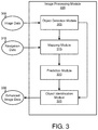
- FIG. 3 is a schematic block diagram of one embodiment of the image processing module 220 .
- the image processing module 220 receives image sequence data 300 , such as image sequence data from a degraded environment.
- An object detection module 305 obtains the image sequence data 300 , such as by using the sensor 120 .
- the object detection module 305 may acquire multiple images that may be part of a video in an environment outside of a vehicle (e.g., mobile vehicle 105 , stationary vehicle 110 ).
- the object detection module 305 may detect a first location of an object 125 on a first image frame of image data based on intensity values corresponding to the first image frame.
- the object detection module 305 may be used to detect and/or track an object 125 in a clear screen that is visible because the environment is not degraded to the point to obscure detection.
- the object detection module 305 may, for example, comprise a software module that, when executed by a processor, operates to detect an object in the first image frame based on intensity values in the first frame, as explained below.
- an object 125 may be detected and tracked from infrared image sequences. Because infrared images have no texture on objects, object detection in infrared images may be based on intensity values of the objects. Thresholding-intensity based detection and saliency based detection may be widely used in object detection from infrared images.
- threshold based techniques a threshold is predetermined; pixels with intensity values larger than the threshold are treated as object pixels; and objects are determined from the object pixels with some size constraint on the detected object.
- saliency based object detection some special filters may be applied to infrared images for computing saliency features; and then thresholding based techniques may be applied to the saliency features for extracting objects.
- saliency based techniques may be more robust than intensity based value based thresholding techniques.
- Kalman filtering and linear prediction models may be used for object tracking in infrared images.
- an object tracking system may be modeled as a linear system by Equation 1.
- the state transition matrix A is given by Equation 2.
- the variable T is a sampling time step.
- the transition matrix may assume that objects have constant accelerations.
- the observation matrix C is given by Equation 3.
- n ⁇ 1 A ⁇ circumflex over (X) ⁇ n ⁇ 1
- n ⁇ 1 A ⁇ circumflex over (P) ⁇ n ⁇ 1
- K n P n
- n ⁇ circumflex over (X) ⁇ n
- n [1 ⁇ K n C ] P n
- Equation 9 ⁇ circumflex over (X) ⁇ 0
- 0 E [ X 0 ] Equation 9
- 0 E [ X 0 X 0 T ] Equation 10
- r n+1 is the future value of an object range
- v n+1 is the future value of object speed
- T is a sampling interval of time.
- Navigation data 310 from a navigation unit and image data (e.g., image frames, image frame data, object data) from the object detection module 305 are provided to a mapping module 315 .
- the mapping module 315 maps (e.g., synchronizes) image frames of the image data to the navigation data. For example, in certain embodiments, each sampling time period corresponding to the navigation data 310 is mapped to an image frame of the image data for the associated time period.
- infrared image frames and the navigation data 310 may have different data rates, which may mean that they may not be sampled at the same time interval. Accordingly, to use the navigation data 310 to process infrared image frames, the mapping module 315 may match the navigation data 310 to the infrared image frames in a time index (e.g., time stamps). In one embodiment, a time instant of navigation data 310 that is the closest to the time instant of an infrared image frame may be used as the matched time instant of the navigation data 310 for a respective infrared image frame. The mapping module 315 may use Equations 15 and 16 to synchronize the infrared image frames and the navigation data 310 .
- a time index e.g., time stamps
- Equations 15 and 16 let t nav (n) be an indexed time for navigation data and t IR (n) be an indexed time for infrared image frames. For the k th infrared image frame, the navigation time index is computed as shown in Equations 15 and 16.
- N k ⁇ i ⁇ I ⁇ : ⁇ ⁇ t nav ⁇ ( i ) - t IR ⁇ ( k ) ⁇ ⁇ ⁇ ⁇ Equation ⁇ ⁇ 16
- the navigation at time t nav (k*) may be used as the matched navigation data 310 for the k th infrared image frame.
- the threshold ⁇ may be set to one millisecond because navigation data 310 may have a higher sampling rate than infrared image frames generally.
- a prediction module 320 determines a location of the object 125 on an image frame of the image data on which the object is not detectable due to an obstruction (e.g., degraded visibility environment 140 ).
- the prediction module 320 may determine the location of the object 125 for moving objects and/or for stationary objects, based on the detected location of the object 125 in preceding image frames that are not obscured as a result of a degraded visibility environment.
- An object identification module 325 uses object data from the object detection module 305 and predicted object locations from the prediction module 320 to identify predicted locations on images where objects are expected to be, when the objects in the image are obscured as a result of a degraded visibility environment.
- the object identification module 325 outputs enhanced image data 330 that may be displayed by the display module 215 .
- the display module 215 may display a representation of the object on the images (by projection onto or overlaying the representation of the object onto the image) in a predicted location where the predicted object is expected to be.
- FIG. 4 is a schematic block diagram of one embodiment of the prediction module 320 .
- the prediction module 320 includes a stationary object prediction module 400 used to predict object locations for stationary objects, and a moving object prediction module 405 used to predict object locations for moving objects.
- the moving object prediction module 405 determines position changes of moving objects on the ground using two types of motions (e.g., the object 125 movement and movement of the mobile vehicle 105 ).
- motion vectors of moving objects may be estimated.
- the mobile vehicle 105 moving dynamics may be estimated from the navigation data 310 , but the object 125 moving dynamics may be unknown; therefore, it may be difficult to obtain the combined movements for the moving objects.
- combined motion of the object 125 and of the mobile vehicle 105 may be assumed to be a smooth linear motion with a constant speed.
- the combined motion is modeled by a linear motion module 410 or a Kalman filter model.
- the linear motion module 410 may generate a linear motion model in response to the object 125 moving and provides information corresponding to the linear motion model to the prediction module 320 to facilitate determining a location of the object 125 .
- the linear motion model may be estimated during a clear image (e.g., seeing phase) without degraded visibility. In an image that has degraded visibility (e.g., a remembering phase), the estimated model may be used for position prediction of moving objects 125 .
- the next position of an object 125 may be given by Equation 17.
- P n+1 P n +v ⁇ t Equation 17
- the speed v is estimated in the seeing phase; the variable ⁇ t is the time interval between the new position and the old position.
- a Kalman gain factor, K(n) is treated as a constant estimated in the seeing phase.
- the next position (e.g., range) of an object may be estimated using Equations 4 through 11.
- i ( n ) r ( n )sin( ⁇ ) Equation 18
- j ( n ) r ( n )cos( ⁇ ) Equation 19
- FIG. 5 is a schematic block diagram of one embodiment of the stationary object prediction module 400 .
- the position changes of stationary objects on the image plane may be mainly determined by the movement of the mobile vehicle 105 because the locations of stationary objects on the ground are fixed, and only the viewing position changes due to the mobile vehicle 105 moving.
- the position changes of the mobile vehicle 105 may be calculated from navigation data.
- New positions of stationary objects on the image plane may be estimated by the movement of the mobile vehicle 105 .
- FIG. 5 illustrates one embodiment of a procedure for the stationary object prediction module 400 to estimate new positions of stationary objects in degraded conditions.
- the stationary object prediction module 400 may receive synchronized navigation data 505 .
- a frame conversion module 510 may convert the synchronized navigation data 505 from a navigation frame to a universal transverse mercator (UTM) system.
- a vehicle position module 515 uses the output from the frame conversion module 510 to estimate a position change of the mobile vehicle 105 .
- a prior known object position 520 and output from the vehicle position module 515 are provided to a position mapping module 525 that maps the prior known object position 520 to a new object position 530 .
- to track stationary objects on the ground may be substantially equivalent to mapping an object from one image plane to another image plane because the objects are stationary and only the viewing position (e.g., image plane) changes.
- the variable s is a scale factor depending on the depth difference of the two image planes to the objects on the ground.
- the matrix T r is a rotation matrix and T t is a translation vector. Both of these may be determined by movement of the mobile vehicle 105 and may be estimated from the navigation data.
- the navigation data may generally be based on the navigation frame (e.g., latitude, longitude).
- the navigation frame may need to be converted to a local coordinate system.
- the frame conversion module 510 converts the navigation frame into the UTM coordinate system.
- the UTM system may use north-east-up (NEU) to represent a three-dimensional coordinate system.
- NEU north-east-up
- Equation 22 through 33 converting may be performed using a set of Equations 22 through 33.
- ⁇ represents latitude; and ⁇ represents longitude.
- the following constants are used.
- Intermediate variables may be calculated using the following equations:
- the UTM coordinates may be calculated by Equations 28 and 29.
- the translation vector may be calculated by Equations 30 through 33.
- rotation matrix may be estimated by a Euler angles approach given by Equations 35 through 38.
- the variables ⁇ , ⁇ , and ⁇ are angle differences in yaw, pitch, and roll from one mobile vehicle 105 position to another position.
- a translation matrix and a rotation matrix may (individually or in combination) be included in a transformation matrix for mapping a location of an object from one image plane to another image plane.
- a representation of the object may be displayed (for example, overlaid on the image) in a predicted location of where the object is expected to be, using the transformation matrix for mapping a location of a visible object from one image plane to another image plane.
- the object detection module 305 , mapping module 310 , prediction module 320 , object identification module 325 , stationary object prediction module 400 , and frame conversion module 510 may comprise software modules that, when executed by a processor, operate to perform algorithms including the equations and steps described above.
- the display module 215 is configured to display on a display device associated with the vehicle a representation of the object on the second image frame in a predicted location where the object is expected to be.
- the representation of the object on the second image frame may be displayed by projecting or overlaying the representation of the object onto the second image frame in a predicted location where the object is expected to be, such that the representation of the object is displayed on a display device of the mobile vehicle to an operator of the vehicle. Accordingly, an operator of the mobile vehicle 105 may therefore better control operation of the vehicle during periods in which images are obscured as a result of a degraded visibility environment, by virtue of the display device displaying the representation of the object that is overlaid on the image in a predicted location where the object is expected to be.
- FIG. 6 is a schematic flow diagram of one embodiment of a method 600 for displaying an object (e.g., the object 125 ).
- the method 600 may include detecting 605 a first location of the object on a first image frame of image data.
- the image data may be infrared data captured by an infrared sensor.
- the first location of the object is detected based on intensity values corresponding to the infrared image data.
- the image data includes multiple images in a video of an environment outside of a vehicle that are acquired in real time using infrared imaging equipment of the vehicle.
- the method 600 may include determining 610 a second location of the object on a second image frame of the image data on which the object is not detectable due to an obstruction (e.g., degraded visibility environment 140 ).
- an obstruction e.g., degraded visibility environment 140
- the method 600 may include displaying 615 a representation of the object on the second image frame.
- the method 600 may include determining whether the object is stationary or moving. In some embodiments, the method 600 includes, in response to the object determined to be stationary, determining the second location of the object on the second image frame based on the first location of the object and a change in position of a vehicle used to capture the image data. In various embodiments, the method 600 includes, in response to the object determined to be moving, determining the second location of the object on the second image frame based on the first location of the object, a predicted location of the object, and a change in position of a vehicle used to capture the image data. In various embodiments, the method 600 includes synchronizing the image data with navigation data of a vehicle.
- instances in this specification where one element is “coupled” to another element can include direct and indirect coupling.
- Direct coupling can be defined as one element coupled to and in some contact with another element.
- Indirect coupling can be defined as coupling between two elements not in direct contact with each other, but having one or more additional elements between the coupled elements.
- securing one element to another element can include direct securing and indirect securing.
- adjacent does not necessarily denote contact. For example, one element can be adjacent another element without being in contact with that element.
- the phrase “at least one of”, when used with a list of items, means different combinations of one or more of the listed items may be used and only one of the items in the list may be needed.
- the item may be a particular object, thing, or category.
- “at least one of” means any combination of items or number of items may be used from the list, but not all of the items in the list may be required.
- “at least one of item A, item B, and item C” may mean item A; item A and item B; item B; item A, item B, and item C; or item B and item C.
- “at least one of item A, item B, and item C” may mean, for example, without limitation, two of item A, one of item B, and ten of item C; four of item B and seven of item C; or some other suitable combination.
- first,” “second,” etc. are used herein merely as labels, and are not intended to impose ordinal, positional, or hierarchical requirements on the items to which these terms refer. Moreover, reference to, e.g., a “second” item does not require or preclude the existence of, e.g., a “first” or lower-numbered item, and/or, e.g., a “third” or higher-numbered item.
- a system, apparatus, structure, article, element, component, or hardware “configured to” perform a specified function is indeed capable of performing the specified function without any alteration, rather than merely having potential to perform the specified function after further modification.
- the system, apparatus, structure, article, element, component, or hardware “configured to” perform a specified function is specifically selected, created, implemented, utilized, programmed, and/or designed for the purpose of performing the specified function.
- “configured to” denotes existing characteristics of a system, apparatus, structure, article, element, component, or hardware which enable the system, apparatus, structure, article, element, component, or hardware to perform the specified function without further modification.
- a system, apparatus, structure, article, element, component, or hardware described as being “configured to” perform a particular function may additionally or alternatively be described as being “adapted to” and/or as being “operative to” perform that function.
- the schematic flow chart diagrams included herein are generally set forth as logical flow chart diagrams. As such, the depicted order and labeled steps are indicative of one embodiment of the presented method. Other steps and methods may be conceived that are equivalent in function, logic, or effect to one or more steps, or portions thereof, of the illustrated method. Additionally, the format and symbols employed are provided to explain the logical steps of the method and are understood not to limit the scope of the method. Although various arrow types and line types may be employed in the flow chart diagrams, they are understood not to limit the scope of the corresponding method. Indeed, some arrows or other connectors may be used to indicate only the logical flow of the method. For instance, an arrow may indicate a waiting or monitoring period of unspecified duration between enumerated steps of the depicted method. Additionally, the order in which a particular method occurs may or may not strictly adhere to the order of the corresponding steps shown.
- Embodiments of the image processing module 220 may take the form of an entirely hardware embodiment, an entirely software embodiment (including firmware, resident software, micro-code, etc.) or an embodiment combining software and hardware aspects that may all generally be referred to herein as a “circuit,” “module” or “system.”
- embodiments may take the form of a program product embodied in one or more computer readable storage devices storing machine readable code, computer readable code, and/or program code, referred hereafter as code.
- the storage devices may be tangible, non-transitory, and/or non-transmission.
- the storage devices may not embody signals. In a certain embodiment, the storage devices only employ signals for accessing code.
- the image processing module 220 may be implemented as a hardware circuit comprising custom VLSI circuits or gate arrays, off-the-shelf semiconductors such as logic chips, transistors, or other discrete components.
- the image processing module 220 may also be implemented in programmable hardware devices such as field programmable gate arrays, programmable array logic, programmable logic devices or the like.
- the image processing module 220 may also be implemented in code and/or software for execution by various types of processors.
- An identified module of code may, for instance, comprise one or more physical or logical blocks of executable code which may, for instance, be organized as an object, procedure, or function. Nevertheless, the executables of an identified module need not be physically located together, but may comprise disparate instructions stored in different locations which, when joined logically together, comprise the module and achieve the stated purpose for the module.
- a module of code may be a single instruction, or many instructions, and may even be distributed over several different code segments, among different programs, and across several memory devices.
- operational data may be identified and illustrated herein within modules, and may be embodied in any suitable form and organized within any suitable type of data structure. The operational data may be collected as a single data set, or may be distributed over different locations including over different computer readable storage devices.
- the software portions are stored on one or more computer readable storage devices.
- the computer readable medium may be a computer readable storage medium.
- the computer readable storage medium may be a storage device storing the code.
- the storage device may be, for example, but not limited to, an electronic, magnetic, optical, electromagnetic, infrared, holographic, micromechanical, or semiconductor system, apparatus, or device, or any suitable combination of the foregoing.
- a storage device More specific examples (a non-exhaustive list) of the storage device would include the following: an electrical connection having one or more wires, a portable computer diskette, a hard disk, a random access memory (RAM), a read-only memory (ROM), an erasable programmable read-only memory (EPROM or Flash memory), a portable compact disc read-only memory (CD-ROM), an optical storage device, a magnetic storage device, or any suitable combination of the foregoing.
- a computer readable storage medium may be any tangible medium that can contain, or store a program for use by or in connection with an instruction execution system, apparatus, or device.
- Code for carrying out operations for embodiments may be written in any combination of one or more programming languages including an object oriented programming language such as Python, Ruby, Java, Smalltalk, C++, or the like, and conventional procedural programming languages, such as the “C” programming language, or the like, and/or machine languages such as assembly languages.
- the code may execute entirely on the user's computer, partly on the user's computer, as a stand-alone software package, partly on the user's computer and partly on a remote computer or entirely on the remote computer or server.
- the remote computer may be connected to the user's computer through any type of network, including a local area network (LAN) or a wide area network (WAN), or the connection may be made to an external computer (for example, through the Internet using an Internet Service Provider).
- LAN local area network
- WAN wide area network
- Internet Service Provider an Internet Service Provider
Landscapes
- Engineering & Computer Science (AREA)
- Physics & Mathematics (AREA)
- General Physics & Mathematics (AREA)
- Remote Sensing (AREA)
- Radar, Positioning & Navigation (AREA)
- Theoretical Computer Science (AREA)
- Aviation & Aerospace Engineering (AREA)
- Computer Vision & Pattern Recognition (AREA)
- Multimedia (AREA)
- Automation & Control Theory (AREA)
- Image Analysis (AREA)
- Signal Processing (AREA)
- Closed-Circuit Television Systems (AREA)
Abstract
Description
{circumflex over (X)} n|n−1 =A{circumflex over (X)} n−1|n−1 Equation 4
{circumflex over (P)} n|n−1 =A{circumflex over (P)} n−1|n−1 A T +Q u Equation 5
K n =P n|n−1 C T[CP n|n−1 C T +Q w]−1 Equation 6
{circumflex over (X)} n|n ={circumflex over (X)} n|n−1 +K n[Y n C{circumflex over (X)} n|n−1] Equation 7
P n|n=[1−K n C]P n|n−1 Equation 8
{circumflex over (X)} 0|0 =E[X 0] Equation 9
P 0|0 =E[X 0 X 0 T] Equation 10
Ŷ n+1 =C{circumflex over (X)} n|n Equation 11
P n+1 =P n +v×Δt Equation 17
i(n)=r(n)sin(θ) Equation 18
j(n)=r(n)cos(θ) Equation 19
p(n)=sTp(n−1) Equation 20
T=[T r ,T t] Equation 21
T t =f[ΔAlt,ΔE,ΔN]T Equation 30
ΔAlt=Alt(n)−Alt(n−1) Equation 31
ΔE=E(n)−E(n−1) Equation 32
ΔN=N(n)−N(n−1) Equation 33
Claims (25)
Priority Applications (1)
| Application Number | Priority Date | Filing Date | Title |
|---|---|---|---|
| US15/607,094 US10549853B2 (en) | 2017-05-26 | 2017-05-26 | Apparatus, system, and method for determining an object's location in image video data |
Applications Claiming Priority (1)
| Application Number | Priority Date | Filing Date | Title |
|---|---|---|---|
| US15/607,094 US10549853B2 (en) | 2017-05-26 | 2017-05-26 | Apparatus, system, and method for determining an object's location in image video data |
Publications (2)
| Publication Number | Publication Date |
|---|---|
| US20180342048A1 US20180342048A1 (en) | 2018-11-29 |
| US10549853B2 true US10549853B2 (en) | 2020-02-04 |
Family
ID=64401355
Family Applications (1)
| Application Number | Title | Priority Date | Filing Date |
|---|---|---|---|
| US15/607,094 Active 2037-08-29 US10549853B2 (en) | 2017-05-26 | 2017-05-26 | Apparatus, system, and method for determining an object's location in image video data |
Country Status (1)
| Country | Link |
|---|---|
| US (1) | US10549853B2 (en) |
Cited By (1)
| Publication number | Priority date | Publication date | Assignee | Title |
|---|---|---|---|---|
| US10951805B2 (en) * | 2017-03-31 | 2021-03-16 | Honda Motor Co., Ltd. | Image generating apparatus and image generating method |
Families Citing this family (1)
| Publication number | Priority date | Publication date | Assignee | Title |
|---|---|---|---|---|
| US10789682B2 (en) | 2017-06-16 | 2020-09-29 | The Boeing Company | Apparatus, system, and method for enhancing an image |
Citations (54)
| Publication number | Priority date | Publication date | Assignee | Title |
|---|---|---|---|---|
| US5526446A (en) | 1991-09-24 | 1996-06-11 | Massachusetts Institute Of Technology | Noise reduction system |
| US5892850A (en) | 1996-04-15 | 1999-04-06 | Olympus Optical Co., Ltd. | Signal processing apparatus capable of correcting high-frequency component of color signal with high precision |
| US6411867B1 (en) * | 1999-10-27 | 2002-06-25 | Fujitsu Ten Limited | Vehicle driving support system, and steering angle detection device |
| US20030099405A1 (en) | 2001-11-21 | 2003-05-29 | Avinash Gopal B. | CT dose reduction filter with a computationally efficient implementation |
| US20030210807A1 (en) | 2002-05-09 | 2003-11-13 | Satoshi Sato | Monitoring device, monitoring method and program for monitoring |
| US20040008904A1 (en) | 2003-07-10 | 2004-01-15 | Samsung Electronics Co., Ltd. | Method and apparatus for noise reduction using discrete wavelet transform |
| US6731436B2 (en) * | 2001-12-28 | 2004-05-04 | Yazaki Corporation | Display apparatus for a vehicle |
| US6801672B1 (en) | 2001-06-01 | 2004-10-05 | Bruce A. Thomas | Removing noise from a color image using wavelets |
| US6805472B2 (en) * | 2001-10-04 | 2004-10-19 | Koito Manufacturing Co., Ltd. | Vehicle light apparatus |
| US20050181399A1 (en) | 2004-01-07 | 2005-08-18 | Okimoto Gordon S. | Methods for enhanced detection & analysis of differentially expressed genes using gene chip microarrays |
| US20050197567A1 (en) | 2004-01-21 | 2005-09-08 | Edda Technology, Inc. | Method and system for intelligent qualitative and quantitative analysis of digital radiography softcopy reading |
| US20050265584A1 (en) | 2004-05-28 | 2005-12-01 | Dobson Stephen E | Imaging systems and methods |
| US20050286764A1 (en) | 2002-10-17 | 2005-12-29 | Anurag Mittal | Method for scene modeling and change detection |
| US20060072014A1 (en) | 2004-08-02 | 2006-04-06 | Geng Z J | Smart optical sensor (SOS) hardware and software platform |
| US7039521B2 (en) * | 2001-08-07 | 2006-05-02 | Siemens Aktiengesellschaft | Method and device for displaying driving instructions, especially in car navigation systems |
| US7068328B1 (en) | 1999-08-17 | 2006-06-27 | Fuji Photo Film Co., Ltd. | Method, apparatus and recording medium for image processing |
| US7151858B2 (en) | 2001-12-21 | 2006-12-19 | Samsung Electronics Co., Ltd. | Wavelet edge map based apparatus and method for edge enhancement |
| US7156542B2 (en) * | 2002-12-13 | 2007-01-02 | Ford Global Technologies, Llc | Vehicle headlight system having digital beam-forming optics |
| US7233233B2 (en) * | 2004-06-14 | 2007-06-19 | Honda Motor Co., Ltd. | Vehicle surroundings monitoring apparatus |
| US7298247B2 (en) * | 2004-04-02 | 2007-11-20 | Denso Corporation | Vehicle periphery monitoring system |
| US7386394B2 (en) * | 2005-01-06 | 2008-06-10 | Doubleshot, Inc. | Navigation and inspection system |
| US7432800B2 (en) * | 2004-07-07 | 2008-10-07 | Delphi Technologies, Inc. | Adaptive lighting display for vehicle collision warning |
| US7433496B2 (en) * | 2001-12-28 | 2008-10-07 | Yazaki Corportion | In-vehicle image correcting device and night driving view field supporting device |
| US7460130B2 (en) | 2000-09-26 | 2008-12-02 | Advantage 3D Llc | Method and system for generation, storage and distribution of omni-directional object views |
| US20080298642A1 (en) | 2006-11-03 | 2008-12-04 | Snowflake Technologies Corporation | Method and apparatus for extraction and matching of biometric detail |
| US7466339B2 (en) * | 2003-04-24 | 2008-12-16 | Denso Corporation | Vehicle-mounted camera apparatus |
| US7583186B2 (en) * | 2004-04-29 | 2009-09-01 | Bayerische Motoren Werke Aktiengesellschaft | Utilization-dependent data representation in a motor vehicle |
| US20090226087A1 (en) | 2008-03-04 | 2009-09-10 | Olympus Corporation | Image processing apparatus, image processing method, and computer-readable storage medium storing image processing program |
| US7592928B2 (en) * | 2005-06-07 | 2009-09-22 | Nissan Motor Co., Ltd. | Image display device and method |
| US20100226590A1 (en) | 2009-03-09 | 2010-09-09 | Samsung Electronics Co., Ltd. | Apparatus and method for reducing noise from an image |
| US20110012910A1 (en) | 2009-07-15 | 2011-01-20 | Microsoft Corporation | Motion field texture synthesis |
| US7970178B2 (en) | 2007-12-21 | 2011-06-28 | Caterpillar Inc. | Visibility range estimation method and system |
| US8023760B1 (en) | 2007-12-06 | 2011-09-20 | The United States Of America As Represented By The Secretary Of The Navy | System and method for enhancing low-visibility imagery |
| US8149245B1 (en) | 2008-12-16 | 2012-04-03 | The United States Of America As Represented By The Secretary Of The Navy | Adaptive linear contrast method for enhancement of low-visibility imagery |
| US8175331B2 (en) * | 2006-01-17 | 2012-05-08 | Honda Motor Co., Ltd. | Vehicle surroundings monitoring apparatus, method, and program |
| US20120257164A1 (en) | 2011-04-07 | 2012-10-11 | The Chinese University Of Hong Kong | Method and device for retinal image analysis |
| US8417053B2 (en) | 2009-12-04 | 2013-04-09 | Huper Laboratories Co., Ltd. | Cleaning method for foggy images |
| US20130235201A1 (en) | 2012-03-07 | 2013-09-12 | Clarion Co., Ltd. | Vehicle Peripheral Area Observation System |
| US8547249B2 (en) * | 2008-10-01 | 2013-10-01 | Universitaet Kassel | Method for avoiding collision |
| US8581982B1 (en) * | 2007-07-30 | 2013-11-12 | Flir Systems, Inc. | Infrared camera vehicle integration systems and methods |
| US20140111541A1 (en) | 2007-03-08 | 2014-04-24 | Sync-Rx, Ltd. | Automatic identification of a tool |
| US20140193032A1 (en) | 2013-01-07 | 2014-07-10 | GM Global Technology Operations LLC | Image super-resolution for dynamic rearview mirror |
| US20140340502A1 (en) | 2013-05-15 | 2014-11-20 | Massachusetts Institute Of Technology | Methods and apparatus for refractive flow measurement with three dimensions and uncertainty |
| US9177363B1 (en) | 2014-09-02 | 2015-11-03 | National Taipei University Of Technology | Method and image processing apparatus for image visibility restoration |
| US20150332512A1 (en) | 2014-05-13 | 2015-11-19 | Nant Vision, Inc. | Augmented reality content rendering via albedo models, systems and methods |
| US9286941B2 (en) | 2001-05-04 | 2016-03-15 | Legend3D, Inc. | Image sequence enhancement and motion picture project management system |
| US9350905B2 (en) | 2014-02-21 | 2016-05-24 | Hitachi Industry & Control Solutions, Ltd. | Image signal processing apparatus, image signal processing method, and image capturing apparatus |
| US9508134B2 (en) | 2015-03-13 | 2016-11-29 | The Boeing Company | Apparatus, system, and method for enhancing image data |
| US9547890B2 (en) | 2013-07-09 | 2017-01-17 | Hitachi Kokusai Electric Inc. | Image processing apparatus and image processing method |
| US20180068418A1 (en) | 2016-09-07 | 2018-03-08 | The Boeing Company | Apparatus, system, and method for enhancing image video data |
| US20180096595A1 (en) | 2016-10-04 | 2018-04-05 | Street Simplified, LLC | Traffic Control Systems and Methods |
| US20180293457A1 (en) | 2017-04-11 | 2018-10-11 | Sony Corporation | System and method for background subtraction in video content |
| US20180365805A1 (en) | 2017-06-16 | 2018-12-20 | The Boeing Company | Apparatus, system, and method for enhancing an image |
| US10274423B2 (en) | 2016-01-21 | 2019-04-30 | Konica Minolta, Inc. | Gas detection device, gas detection method, and gas detection program |
-
2017
- 2017-05-26 US US15/607,094 patent/US10549853B2/en active Active
Patent Citations (58)
| Publication number | Priority date | Publication date | Assignee | Title |
|---|---|---|---|---|
| US5526446A (en) | 1991-09-24 | 1996-06-11 | Massachusetts Institute Of Technology | Noise reduction system |
| US5892850A (en) | 1996-04-15 | 1999-04-06 | Olympus Optical Co., Ltd. | Signal processing apparatus capable of correcting high-frequency component of color signal with high precision |
| US7068328B1 (en) | 1999-08-17 | 2006-06-27 | Fuji Photo Film Co., Ltd. | Method, apparatus and recording medium for image processing |
| US6411867B1 (en) * | 1999-10-27 | 2002-06-25 | Fujitsu Ten Limited | Vehicle driving support system, and steering angle detection device |
| US6567726B2 (en) * | 1999-10-27 | 2003-05-20 | Fujitsu Ten Limited | Vehicle driving support system, and steering angle detection device |
| US7460130B2 (en) | 2000-09-26 | 2008-12-02 | Advantage 3D Llc | Method and system for generation, storage and distribution of omni-directional object views |
| US9286941B2 (en) | 2001-05-04 | 2016-03-15 | Legend3D, Inc. | Image sequence enhancement and motion picture project management system |
| US6801672B1 (en) | 2001-06-01 | 2004-10-05 | Bruce A. Thomas | Removing noise from a color image using wavelets |
| US7039521B2 (en) * | 2001-08-07 | 2006-05-02 | Siemens Aktiengesellschaft | Method and device for displaying driving instructions, especially in car navigation systems |
| US6805472B2 (en) * | 2001-10-04 | 2004-10-19 | Koito Manufacturing Co., Ltd. | Vehicle light apparatus |
| US20030099405A1 (en) | 2001-11-21 | 2003-05-29 | Avinash Gopal B. | CT dose reduction filter with a computationally efficient implementation |
| US7151858B2 (en) | 2001-12-21 | 2006-12-19 | Samsung Electronics Co., Ltd. | Wavelet edge map based apparatus and method for edge enhancement |
| US7433496B2 (en) * | 2001-12-28 | 2008-10-07 | Yazaki Corportion | In-vehicle image correcting device and night driving view field supporting device |
| US6731436B2 (en) * | 2001-12-28 | 2004-05-04 | Yazaki Corporation | Display apparatus for a vehicle |
| US20030210807A1 (en) | 2002-05-09 | 2003-11-13 | Satoshi Sato | Monitoring device, monitoring method and program for monitoring |
| US20050286764A1 (en) | 2002-10-17 | 2005-12-29 | Anurag Mittal | Method for scene modeling and change detection |
| US7156542B2 (en) * | 2002-12-13 | 2007-01-02 | Ford Global Technologies, Llc | Vehicle headlight system having digital beam-forming optics |
| US7466339B2 (en) * | 2003-04-24 | 2008-12-16 | Denso Corporation | Vehicle-mounted camera apparatus |
| US20040008904A1 (en) | 2003-07-10 | 2004-01-15 | Samsung Electronics Co., Ltd. | Method and apparatus for noise reduction using discrete wavelet transform |
| US20050181399A1 (en) | 2004-01-07 | 2005-08-18 | Okimoto Gordon S. | Methods for enhanced detection & analysis of differentially expressed genes using gene chip microarrays |
| US20050197567A1 (en) | 2004-01-21 | 2005-09-08 | Edda Technology, Inc. | Method and system for intelligent qualitative and quantitative analysis of digital radiography softcopy reading |
| US7298247B2 (en) * | 2004-04-02 | 2007-11-20 | Denso Corporation | Vehicle periphery monitoring system |
| US7583186B2 (en) * | 2004-04-29 | 2009-09-01 | Bayerische Motoren Werke Aktiengesellschaft | Utilization-dependent data representation in a motor vehicle |
| US20050265584A1 (en) | 2004-05-28 | 2005-12-01 | Dobson Stephen E | Imaging systems and methods |
| US7233233B2 (en) * | 2004-06-14 | 2007-06-19 | Honda Motor Co., Ltd. | Vehicle surroundings monitoring apparatus |
| US7432800B2 (en) * | 2004-07-07 | 2008-10-07 | Delphi Technologies, Inc. | Adaptive lighting display for vehicle collision warning |
| US20060072014A1 (en) | 2004-08-02 | 2006-04-06 | Geng Z J | Smart optical sensor (SOS) hardware and software platform |
| US7386394B2 (en) * | 2005-01-06 | 2008-06-10 | Doubleshot, Inc. | Navigation and inspection system |
| US7592928B2 (en) * | 2005-06-07 | 2009-09-22 | Nissan Motor Co., Ltd. | Image display device and method |
| US8175331B2 (en) * | 2006-01-17 | 2012-05-08 | Honda Motor Co., Ltd. | Vehicle surroundings monitoring apparatus, method, and program |
| US20080298642A1 (en) | 2006-11-03 | 2008-12-04 | Snowflake Technologies Corporation | Method and apparatus for extraction and matching of biometric detail |
| US20140111541A1 (en) | 2007-03-08 | 2014-04-24 | Sync-Rx, Ltd. | Automatic identification of a tool |
| US8581982B1 (en) * | 2007-07-30 | 2013-11-12 | Flir Systems, Inc. | Infrared camera vehicle integration systems and methods |
| US8023760B1 (en) | 2007-12-06 | 2011-09-20 | The United States Of America As Represented By The Secretary Of The Navy | System and method for enhancing low-visibility imagery |
| US7970178B2 (en) | 2007-12-21 | 2011-06-28 | Caterpillar Inc. | Visibility range estimation method and system |
| US20090226087A1 (en) | 2008-03-04 | 2009-09-10 | Olympus Corporation | Image processing apparatus, image processing method, and computer-readable storage medium storing image processing program |
| US8547249B2 (en) * | 2008-10-01 | 2013-10-01 | Universitaet Kassel | Method for avoiding collision |
| US8149245B1 (en) | 2008-12-16 | 2012-04-03 | The United States Of America As Represented By The Secretary Of The Navy | Adaptive linear contrast method for enhancement of low-visibility imagery |
| US20100226590A1 (en) | 2009-03-09 | 2010-09-09 | Samsung Electronics Co., Ltd. | Apparatus and method for reducing noise from an image |
| US20110012910A1 (en) | 2009-07-15 | 2011-01-20 | Microsoft Corporation | Motion field texture synthesis |
| US8417053B2 (en) | 2009-12-04 | 2013-04-09 | Huper Laboratories Co., Ltd. | Cleaning method for foggy images |
| US20120257164A1 (en) | 2011-04-07 | 2012-10-11 | The Chinese University Of Hong Kong | Method and device for retinal image analysis |
| US20130235201A1 (en) | 2012-03-07 | 2013-09-12 | Clarion Co., Ltd. | Vehicle Peripheral Area Observation System |
| US20140193032A1 (en) | 2013-01-07 | 2014-07-10 | GM Global Technology Operations LLC | Image super-resolution for dynamic rearview mirror |
| US20140340502A1 (en) | 2013-05-15 | 2014-11-20 | Massachusetts Institute Of Technology | Methods and apparatus for refractive flow measurement with three dimensions and uncertainty |
| US9842404B2 (en) | 2013-05-15 | 2017-12-12 | Massachusetts Institite Of Technology | Methods and apparatus for refractive flow measurement with three dimensions and uncertainty |
| US20150016690A1 (en) | 2013-05-15 | 2015-01-15 | Massachusetts Institute Of Technology | Methods and apparatus for refractive flow measurement |
| US9710917B2 (en) | 2013-05-15 | 2017-07-18 | Massachusetts Institute Of Technology | Methods and apparatus for refractive flow measurement |
| US9547890B2 (en) | 2013-07-09 | 2017-01-17 | Hitachi Kokusai Electric Inc. | Image processing apparatus and image processing method |
| US9350905B2 (en) | 2014-02-21 | 2016-05-24 | Hitachi Industry & Control Solutions, Ltd. | Image signal processing apparatus, image signal processing method, and image capturing apparatus |
| US20150332512A1 (en) | 2014-05-13 | 2015-11-19 | Nant Vision, Inc. | Augmented reality content rendering via albedo models, systems and methods |
| US9177363B1 (en) | 2014-09-02 | 2015-11-03 | National Taipei University Of Technology | Method and image processing apparatus for image visibility restoration |
| US9508134B2 (en) | 2015-03-13 | 2016-11-29 | The Boeing Company | Apparatus, system, and method for enhancing image data |
| US10274423B2 (en) | 2016-01-21 | 2019-04-30 | Konica Minolta, Inc. | Gas detection device, gas detection method, and gas detection program |
| US20180068418A1 (en) | 2016-09-07 | 2018-03-08 | The Boeing Company | Apparatus, system, and method for enhancing image video data |
| US20180096595A1 (en) | 2016-10-04 | 2018-04-05 | Street Simplified, LLC | Traffic Control Systems and Methods |
| US20180293457A1 (en) | 2017-04-11 | 2018-10-11 | Sony Corporation | System and method for background subtraction in video content |
| US20180365805A1 (en) | 2017-06-16 | 2018-12-20 | The Boeing Company | Apparatus, system, and method for enhancing an image |
Non-Patent Citations (1)
| Title |
|---|
| Comaniciu et al., Mean Shift Analysis and Applications, Department of Electrical and Computer Engineering, Rutgers University, pp. 1-8, accessed from http://comaniciu.net/Papers/MsAnalysis.pdf on Nov. 7, 2016. |
Cited By (1)
| Publication number | Priority date | Publication date | Assignee | Title |
|---|---|---|---|---|
| US10951805B2 (en) * | 2017-03-31 | 2021-03-16 | Honda Motor Co., Ltd. | Image generating apparatus and image generating method |
Also Published As
| Publication number | Publication date |
|---|---|
| US20180342048A1 (en) | 2018-11-29 |
Similar Documents
| Publication | Publication Date | Title |
|---|---|---|
| US10339387B2 (en) | Automated multiple target detection and tracking system | |
| US11064178B2 (en) | Deep virtual stereo odometry | |
| US11205274B2 (en) | High-performance visual object tracking for embedded vision systems | |
| US11430199B2 (en) | Feature recognition assisted super-resolution method | |
| US20190080467A1 (en) | Pose determination with semantic segmentation | |
| TWI796401B (en) | Cluttered background removal from imagery for object detection | |
| US20160283774A1 (en) | Cloud feature detection | |
| US20180075614A1 (en) | Method of Depth Estimation Using a Camera and Inertial Sensor | |
| KR102917989B1 (en) | Method and System for Vehicle Pose Estimation using Optical Flow for Inter-Vehicle Distance Compensation in Dynamic Scenes | |
| Dusha et al. | Fixed-wing attitude estimation using computer vision based horizon detection | |
| Helgesen et al. | Real-time georeferencing of thermal images using small fixed-wing UAVs in maritime environments | |
| CN110443247A (en) | A kind of unmanned aerial vehicle moving small target real-time detecting system and method | |
| WO2022055795A1 (en) | Damage detection based on images with varying resolutions | |
| Tulpan et al. | Experimental evaluation of four feature detection methods for close range and distant airborne targets for Unmanned Aircraft Systems applications | |
| US10549853B2 (en) | Apparatus, system, and method for determining an object's location in image video data | |
| EP2731050A1 (en) | Cloud feature detection | |
| Das et al. | Taming the north: Multi-camera parallel tracking and mapping in snow-laden environments | |
| US12100203B2 (en) | Above-horizon target tracking | |
| Pinto et al. | An architecture for visual motion perception of a surveillance-based autonomous robot | |
| US20250200760A1 (en) | Motion-based target tracking | |
| Vadlamani et al. | A novel indoor positioning system for unprepared firefighting scenarios | |
| Liu et al. | A joint optical flow and principal component analysis approach for motion detection | |
| CN118552885B (en) | Cableway intrusion event analysis and early warning method | |
| US20260120317A1 (en) | Systems and methods for image tracking with monocular imagery | |
| Gatter et al. | On precisely determining self-cast shadow regions in aerial camera images |
Legal Events
| Date | Code | Title | Description |
|---|---|---|---|
| AS | Assignment |
Owner name: THE BOEING COMPANY, ILLINOIS Free format text: ASSIGNMENT OF ASSIGNORS INTEREST;ASSIGNORS:JIANG, QIN;OWECHKO, YURI;KIM, KYUNGNAM;SIGNING DATES FROM 20170525 TO 20170526;REEL/FRAME:042519/0519 |
|
| STPP | Information on status: patent application and granting procedure in general |
Free format text: RESPONSE TO NON-FINAL OFFICE ACTION ENTERED AND FORWARDED TO EXAMINER |
|
| STPP | Information on status: patent application and granting procedure in general |
Free format text: NON FINAL ACTION MAILED |
|
| STPP | Information on status: patent application and granting procedure in general |
Free format text: NOTICE OF ALLOWANCE MAILED -- APPLICATION RECEIVED IN OFFICE OF PUBLICATIONS |
|
| STPP | Information on status: patent application and granting procedure in general |
Free format text: AWAITING TC RESP., ISSUE FEE NOT PAID |
|
| STPP | Information on status: patent application and granting procedure in general |
Free format text: PUBLICATIONS -- ISSUE FEE PAYMENT VERIFIED |
|
| STCF | Information on status: patent grant |
Free format text: PATENTED CASE |
|
| MAFP | Maintenance fee payment |
Free format text: PAYMENT OF MAINTENANCE FEE, 4TH YEAR, LARGE ENTITY (ORIGINAL EVENT CODE: M1551); ENTITY STATUS OF PATENT OWNER: LARGE ENTITY Year of fee payment: 4 |