US10548428B2 - Beverage preparation unit - Google Patents
Beverage preparation unit Download PDFInfo
- Publication number
- US10548428B2 US10548428B2 US15/303,153 US201515303153A US10548428B2 US 10548428 B2 US10548428 B2 US 10548428B2 US 201515303153 A US201515303153 A US 201515303153A US 10548428 B2 US10548428 B2 US 10548428B2
- Authority
- US
- United States
- Prior art keywords
- beverage
- capsule
- brewing unit
- receptacle
- liquid
- Prior art date
- Legal status (The legal status is an assumption and is not a legal conclusion. Google has not performed a legal analysis and makes no representation as to the accuracy of the status listed.)
- Expired - Fee Related, expires
Links
Images


Classifications
-
- A—HUMAN NECESSITIES
- A47—FURNITURE; DOMESTIC ARTICLES OR APPLIANCES; COFFEE MILLS; SPICE MILLS; SUCTION CLEANERS IN GENERAL
- A47J—KITCHEN EQUIPMENT; COFFEE MILLS; SPICE MILLS; APPARATUS FOR MAKING BEVERAGES
- A47J31/00—Apparatus for making beverages
- A47J31/24—Coffee-making apparatus in which hot water is passed through the filter under pressure, i.e. in which the coffee grounds are extracted under pressure
- A47J31/34—Coffee-making apparatus in which hot water is passed through the filter under pressure, i.e. in which the coffee grounds are extracted under pressure with hot water under liquid pressure
- A47J31/36—Coffee-making apparatus in which hot water is passed through the filter under pressure, i.e. in which the coffee grounds are extracted under pressure with hot water under liquid pressure with mechanical pressure-producing means
- A47J31/3666—Coffee-making apparatus in which hot water is passed through the filter under pressure, i.e. in which the coffee grounds are extracted under pressure with hot water under liquid pressure with mechanical pressure-producing means whereby the loading of the brewing chamber with the brewing material is performed by the user
- A47J31/3676—Cartridges being employed
- A47J31/369—Impermeable cartridges being employed
- A47J31/3695—Cartridge perforating means for creating the hot water inlet
-
- A—HUMAN NECESSITIES
- A47—FURNITURE; DOMESTIC ARTICLES OR APPLIANCES; COFFEE MILLS; SPICE MILLS; SUCTION CLEANERS IN GENERAL
- A47J—KITCHEN EQUIPMENT; COFFEE MILLS; SPICE MILLS; APPARATUS FOR MAKING BEVERAGES
- A47J31/00—Apparatus for making beverages
- A47J31/24—Coffee-making apparatus in which hot water is passed through the filter under pressure, i.e. in which the coffee grounds are extracted under pressure
-
- A—HUMAN NECESSITIES
- A47—FURNITURE; DOMESTIC ARTICLES OR APPLIANCES; COFFEE MILLS; SPICE MILLS; SUCTION CLEANERS IN GENERAL
- A47J—KITCHEN EQUIPMENT; COFFEE MILLS; SPICE MILLS; APPARATUS FOR MAKING BEVERAGES
- A47J31/00—Apparatus for making beverages
- A47J31/005—Portable or compact beverage making apparatus, e.g. for travelling, for use in automotive vehicles
-
- A—HUMAN NECESSITIES
- A47—FURNITURE; DOMESTIC ARTICLES OR APPLIANCES; COFFEE MILLS; SPICE MILLS; SUCTION CLEANERS IN GENERAL
- A47J—KITCHEN EQUIPMENT; COFFEE MILLS; SPICE MILLS; APPARATUS FOR MAKING BEVERAGES
- A47J31/00—Apparatus for making beverages
- A47J31/24—Coffee-making apparatus in which hot water is passed through the filter under pressure, i.e. in which the coffee grounds are extracted under pressure
- A47J31/34—Coffee-making apparatus in which hot water is passed through the filter under pressure, i.e. in which the coffee grounds are extracted under pressure with hot water under liquid pressure
- A47J31/36—Coffee-making apparatus in which hot water is passed through the filter under pressure, i.e. in which the coffee grounds are extracted under pressure with hot water under liquid pressure with mechanical pressure-producing means
- A47J31/3604—Coffee-making apparatus in which hot water is passed through the filter under pressure, i.e. in which the coffee grounds are extracted under pressure with hot water under liquid pressure with mechanical pressure-producing means with a mechanism arranged to move the brewing chamber between loading, infusing and ejecting stations
- A47J31/3623—Cartridges being employed
-
- A—HUMAN NECESSITIES
- A47—FURNITURE; DOMESTIC ARTICLES OR APPLIANCES; COFFEE MILLS; SPICE MILLS; SUCTION CLEANERS IN GENERAL
- A47J—KITCHEN EQUIPMENT; COFFEE MILLS; SPICE MILLS; APPARATUS FOR MAKING BEVERAGES
- A47J31/00—Apparatus for making beverages
- A47J31/44—Parts or details or accessories of beverage-making apparatus
- A47J31/4403—Constructional details
-
- A—HUMAN NECESSITIES
- A47—FURNITURE; DOMESTIC ARTICLES OR APPLIANCES; COFFEE MILLS; SPICE MILLS; SUCTION CLEANERS IN GENERAL
- A47J—KITCHEN EQUIPMENT; COFFEE MILLS; SPICE MILLS; APPARATUS FOR MAKING BEVERAGES
- A47J31/00—Apparatus for making beverages
- A47J31/44—Parts or details or accessories of beverage-making apparatus
- A47J31/46—Dispensing spouts, pumps, drain valves or like liquid transporting devices
- A47J31/462—Dispensing spouts, pumps, drain valves or like liquid transporting devices with an intermediate liquid storage tank
- A47J31/467—Dispensing spouts, pumps, drain valves or like liquid transporting devices with an intermediate liquid storage tank for the infusion
-
- A—HUMAN NECESSITIES
- A47—FURNITURE; DOMESTIC ARTICLES OR APPLIANCES; COFFEE MILLS; SPICE MILLS; SUCTION CLEANERS IN GENERAL
- A47J—KITCHEN EQUIPMENT; COFFEE MILLS; SPICE MILLS; APPARATUS FOR MAKING BEVERAGES
- A47J31/00—Apparatus for making beverages
- A47J31/44—Parts or details or accessories of beverage-making apparatus
- A47J31/54—Water boiling vessels in beverage making machines
- A47J31/56—Water boiling vessels in beverage making machines having water-level controls; having temperature controls
-
- A—HUMAN NECESSITIES
- A47—FURNITURE; DOMESTIC ARTICLES OR APPLIANCES; COFFEE MILLS; SPICE MILLS; SUCTION CLEANERS IN GENERAL
- A47J—KITCHEN EQUIPMENT; COFFEE MILLS; SPICE MILLS; APPARATUS FOR MAKING BEVERAGES
- A47J31/00—Apparatus for making beverages
- A47J31/24—Coffee-making apparatus in which hot water is passed through the filter under pressure, i.e. in which the coffee grounds are extracted under pressure
- A47J31/34—Coffee-making apparatus in which hot water is passed through the filter under pressure, i.e. in which the coffee grounds are extracted under pressure with hot water under liquid pressure
- A47J31/36—Coffee-making apparatus in which hot water is passed through the filter under pressure, i.e. in which the coffee grounds are extracted under pressure with hot water under liquid pressure with mechanical pressure-producing means
- A47J31/3604—Coffee-making apparatus in which hot water is passed through the filter under pressure, i.e. in which the coffee grounds are extracted under pressure with hot water under liquid pressure with mechanical pressure-producing means with a mechanism arranged to move the brewing chamber between loading, infusing and ejecting stations
- A47J31/3623—Cartridges being employed
- A47J31/3628—Perforating means therefor
-
- A—HUMAN NECESSITIES
- A47—FURNITURE; DOMESTIC ARTICLES OR APPLIANCES; COFFEE MILLS; SPICE MILLS; SUCTION CLEANERS IN GENERAL
- A47J—KITCHEN EQUIPMENT; COFFEE MILLS; SPICE MILLS; APPARATUS FOR MAKING BEVERAGES
- A47J31/00—Apparatus for making beverages
- A47J31/24—Coffee-making apparatus in which hot water is passed through the filter under pressure, i.e. in which the coffee grounds are extracted under pressure
- A47J31/34—Coffee-making apparatus in which hot water is passed through the filter under pressure, i.e. in which the coffee grounds are extracted under pressure with hot water under liquid pressure
- A47J31/36—Coffee-making apparatus in which hot water is passed through the filter under pressure, i.e. in which the coffee grounds are extracted under pressure with hot water under liquid pressure with mechanical pressure-producing means
- A47J31/3666—Coffee-making apparatus in which hot water is passed through the filter under pressure, i.e. in which the coffee grounds are extracted under pressure with hot water under liquid pressure with mechanical pressure-producing means whereby the loading of the brewing chamber with the brewing material is performed by the user
- A47J31/3676—Cartridges being employed
- A47J31/369—Impermeable cartridges being employed
Definitions
- the presently disclosed and/or claimed inventive concept(s) relates to a system for preparing a beverage from a beverage ingredients containing capsule.
- the presently disclosed and/or claimed inventive concept(s) relates to a beverage preparation device for enhanced dispensing of a beverage from the device.
- Devices for preparation of a beverage such as coffee or tea from ingredients containing capsules are well-known in the prior art. These devices are generally stationary devices equipped with a liquid tank, a pump and heating means in order to provide pressurized, heated liquid through a capsule inserted into the device. The liquid is injected into the capsule and will interact with the ingredients provided in the capsule. The resulting beverage is then drained from the capsule and may be collected in a dedicated receiving vessel.
- a drawback of the known systems is the fact that these devices are designed for stationary use only. This means that the device has to be placed at a fixed location within the household, close to a main power supply. In addition, the device has to be placed close to a water supply in order to enable filling or re-filling of the liquid into a liquid tank of the device. The beverage preparation can thus only be carried out at a predefined stationary location of the device.
- EP 1 277 428 for example relates to an espresso coffee machine designed for use in conjunction with a low-voltage power supply of a vehicle, the machine comprising a water reservoir connected to a pump to convey water to a heating element, which itself is connected to an extraction head for providing a portion of coffee.
- the extraction head of the device is arranged for pouring a predefined portion of coffee beverage from above into a provided receiving vessel.
- U.S. 2009/0029021 relates to a portable device for brewing a coffee beverage, the device comprising a water tank, a housing including a chamber presenting a hot water feed nozzle and an opening through which a fill of brew preparation can be inserted, a closure part for closing said chamber, means connected to the tank to act during a brewing cycle to deliver a certain volume of water that has been raised to a brewing temperature from said tank to said chamber, and a brew outflow orifice from which the resulting beverage may be poured into a suitable receiving vessel.
- the body of the device includes handle means enabling the outflow orifice to be placed, during the brewing cycle, to face down towards a receptacle such as e.g. a cup for collecting the beverage.
- a major drawback of the known devices is the fact that the outlet orifice are generally arranged for pouring the prepared beverage from the device into a dedicated receiving vessel held below the outlet orifice.
- the consumer is likely to spill at least part of the beverage during the draining from such outlet orifice.
- an enhanced solution is sought-after which enables a convenient and clean transfer of a beverage prepared by the portable beverage preparation device to a dedicated receiving vessel.
- FIG. 1 a is a perspective side view of a particular (but non-limiting) embodiment of the portable beverage preparation device being connected to a docking station.
- FIG. 1 b is a perspective exploded assembly drawing of a system comprising the portable beverage preparation device as shown in FIG. 1 a , a docking station and a battery unit.
- FIG. 2 relates to a sectional side view of a particular (but non-limiting) embodiment of the portable beverage preparation device in a storage or transport position.
- FIGS. 3 a to 3 c are sectional side views of the portable beverage preparation device during provision of a capsule into the brewing unit of the device.
- FIG. 3 d is a partial sectional side view of the device in an operation state of the device, i.e. during beverage production.
- FIG. 4 a is a perspective view from above of a particular (but non-limiting) embodiment of the beverage brewing unit of the beverage preparation device
- FIG. 4 b is a perspective view from below of a particular (but non-limiting) embodiment of the beverage brewing unit of the device.
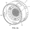
- FIG. 4 c is a perspective side view of a particular (but non-limiting) embodiment of a lid member for being connected to the housing of the device.
- FIGS. 5 a and 5 b relate to a particular (but non-limiting) embodiment of a receptacle for being connected to the device according to the presently disclosed and/or claimed inventive concept(s), the receptacle comprising selective openable valve means.
- FIG. 5 c relates to a bottom view of a particular (but non-limiting) embodiment of the receptacle as shown in FIGS. 5 a and 5 b.
- the presently disclosed and/or claimed inventive concept(s) relates to a beverage preparation device for preparing a beverage from an ingredients containing capsule, the device comprising a beverage brewing unit for receiving the capsule and preparing the beverage from the ingredients within the capsule by means of injection of pressurized liquid into the capsule, beverage dispensing means connected to the beverage brewing unit and designed to selectively connect to a bottom of a receptacle for dispensing the resulting beverage into the receptacle, wherein beverage brewing unit is designed for passing liquid through the capsule in a direction essentially opposite to gravity.
- the device enables the preparation and supply of beverage to a dedicated receptacle, whereby filling of the receptacle with the beverage is obtained from below through a bottom wall of the receptacle. Accordingly, spilling of the beverage during provision of the beverage from the device to the receptacle is effectively prevented.
- the device according to the presently disclosed and/or claimed inventive concept(s) is a portable device.
- the device may also be a stationary device.
- the term “portable” beverage preparation device is to be understood as suitable for being used at remote places by contrast to a stationary beverage preparation device.
- the portable beverage preparation device according to the presently disclosed and/or claimed inventive concept(s) is designed for being used in transport such as e.g. in vehicles which, in certain non-limiting embodiments, provide low voltage current supply, for use outdoor, e.g. by means of using a battery pack, and/or at home or at the office.
- the beverage preparation device is designed for being provided with a low voltage current supply.
- the beverage preparation device may be designed for being selectively connected to a battery pack and/or a docking station or power converter unit.
- the beverage preparation device is designed for preparing espresso-type coffee at high pressure requiring high water pressure supply and high water temperature setting.
- the beverage preparation device comprises a pump, a heating unit and a liquid reservoir connected to the pump and the heating unit. Accordingly, hot pressurized liquid may be provided to the beverage brewing unit of the device.
- the device is designed for preparing a beverage at a high pressure of between 10 to 15 bar.
- the heating means of the device comprises two cartridge heaters designed for being supplied with 12 Volts nominal voltage.
- the pump of the device is a membrane pump. In certain non-limiting embodiments, the pump is vibration-decoupled from a housing of the device.
- the liquid reservoir comprises a volume of between 30 to 100 ml, such as (but not limited to) between 40 and 60 ml.
- the liquid reservoir comprises a volume to prepare a single beverage cup with the liquid contained therein, in particular a cup of espresso-type beverage. Due to the little volume of the liquid reservoir, heating of the liquid contained therein is accelerated.
- the heating means are, in certain non-limiting embodiments, designed for heating the liquid contained in the reservoir to about 90° C. in 2-4 minutes, such as (but not limited to) in about 3 minutes.
- the beverage brewing unit comprises liquid inlet means connected to the liquid reservoir, the pump and the heating unit of the device. Accordingly, hot pressurized liquid such as water may be fed to the beverage brewing unit respectively to a capsule received by the beverage brewing unit.
- the liquid inlet means may be connected to an injection or opening member arranged within the beverage brewing unit to open an inlet face of the capsule.
- the beverage dispensing means are extending from the beverage brewing unit at a side essentially opposite to the liquid inlet means.
- the liquid inlet means are arranged at a lower portion of the beverage brewing unit.
- the beverage dispensing means are connected to an upper portion of the beverage brewing unit.
- the liquid reservoir is, in certain non-limiting embodiments, arranged below the beverage brewing unit and the beverage dispensing means.
- the beverage dispensing means are arranged above the beverage brewing unit.
- a receptacle to be filled is arranged above the beverage brewing unit and the beverage dispensing means.
- at least the pump, the beverage brewing unit and the beverage dispensing means of the device are desirably arranged essentially vertically, such as in particular vertically stacked within the device.
- the flow path of liquid through the beverage brewing unit and the beverage dispensing means is in a common upward direction.
- the flow path of liquid from the pump of the device to the beverage brewing unit and the beverage dispensing means is in a common direction.
- the flow path of liquid through the device is without change of direction of the liquid flow.
- the distances between the individual components of the device are minimized such as to obtain a very compact arrangement of the beverage preparation device.
- the tubing necessary to fluidly connect the individual parts of the device may be shortened and hence, the amount of residual water to heat is minimized.
- the dispensing means comprise an injection member protruding from a support surface for the receptacle.
- the support surface is a plane and/or round surface arranged at a top portion of the beverage preparation device.
- the beverage preparation device comprises a housing and a lid member that may be selectively connected to the housing.
- the lid member is designed for enclosing a capsule within the brewing unit of the device. Thereby, the lid member may form an upper portion of the brewing unit.
- the lid member On its upper portion, the lid member comprises, in certain non-limiting embodiments, the support surface for the receptacle from which the injection member protrudes.
- the lid member comprises the dispensing means of the device.
- the lid member may comprise capsule opening means such as in particular a pyramidal plate against which an outlet face of a capsule inserted into the brewing unit is urged upon rising pressure within the capsule during injection of liquid thereto.
- the pyramidal plate comprises small orifices or interstices through which the beverage exiting the capsule at an upper outlet surface thereof may flow upwardly towards the injection member of the dispensing means. The resulting beverage may thus be fed from the brewing unit via the beverage dispensing means of the lid member to the receptacle arranged above the beverage dispensing means.
- the lid member is designed for being connected to a top portion of the housing of the device. Thereby, the lid member may be screwed or snap-fitted at the circumference of the housing of the device.
- the lid member comprises an outer circumferential lid portion and an inner central lid portion which are arranged rotatably relative to each other.
- the outer lid portion may comprise connection means for being connected to the housing of the device. Thereby, the connection means may engage dedicated recesses or connecting elements arranged at the housing of the device.
- the outer lid member may be rotated and thus disconnected from the housing while the inner lid portion will not undergo a rotational movement with respect to the beverage brewing unit and a capsule contained therein.
- This arrangement enables that a complete destruction of the capsule outlet membrane respectively outlet face when re-opening the lid member after extraction, during which an outlet face of the capsule was urged and teared by the pyramidal plate of the lid member, is prevented.
- the brewing unit of the device is designed to accommodate a rotational-symmetric capsule comprising a truncated-cone shaped body portion and a membrane connected to a circumferential rim portion of the body portion and constituting an outlet face thereof.
- the capsule is arranged within the brewing unit such that the circumferential rim portion and the membrane connected thereto are arranged at the upper side of the capsule.
- the brewing unit may further comprise an ejection mechanism designed to eject the capsule from the brewing unit after the beverage preparation.
- a further aspect of the presently disclosed and/or claimed inventive concept(s) relates to a portable beverage preparation device for preparing a beverage from an ingredients containing capsule, the device comprising a beverage brewing unit for receiving the capsule and preparing the beverage from the ingredients within the capsule by means of injection of pressurized liquid into the capsule, a lid member selectively connectable to the brewing unit in order to enclose a capsule provided thereto, wherein the lid member, in certain non-limiting embodiments, comprises beverage dispensing means designed to selectively connect to a bottom of a receptacle, and wherein the beverage brewing unit (or at least a part of it) is arranged moveable within a housing of the device such as to selectively open a fluid-connection from the brewing unit to a fluid reservoir of the device.
- the fluid-connection from the brewing unit to the fluid reservoir is opened dependent on the provision of the lid member to the device respectively the brewing unit.
- the beverage brewing unit is, in certain non-limiting embodiments, urged in a direction away from the fluid reservoir such as to open a dedicated valve means, e.g. an annular passage enabling fluid flow from the beverage brewing unit to the liquid reservoir.
- a dedicated valve means e.g. an annular passage enabling fluid flow from the beverage brewing unit to the liquid reservoir.
- the valve means e.g. the annular fluid passage from the brewing unit to the liquid reservoir is closed.
- the presently disclosed and/or claimed inventive concept(s) relates to a system comprising a portable beverage preparation device as described here-above and a receptacle.
- the receptacle for being connected to the device comprises inlet means such as a valve or selectively openable aperture that is integrally formed in the bottom wall of the receptacle.
- the inlet means may for example be a valve or a self-closing membrane.
- the closing strength of the valve or the membrane is selected to ensure that it can withstand at least the pressure exerted on it by liquid in the receptacle, in case the receptacle is filled completely, without any leakage.
- the presently disclosed and/or claimed inventive concept(s) relates to a method for preparing a beverage from ingredients contained within a capsule, the method comprising the steps of: connecting a beverage receptacle to a beverage dispensing means of a beverage preparation device, passing liquid through a capsule in a direction essentially opposite to gravity, dispensing the resulting beverage into the receptacle through a bottom of the receptacle.
- the capsule is thereby held within a dedicated beverage brewing unit to which the capsule may be selectively be inserted.
- the method further comprises the step of passing the liquid from a pump of the device through the capsule into the receptacle in a common direction, i.e. without change of direction of the liquid flow.
- the liquid is pressurized hot water.
- the device according to the presently disclosed and/or claimed inventive concept(s) is designed to enable the preparation of a plurality of different types of hot and/or cold liquid comestibles such as e.g. coffee, tea, milk, soup of the like.
- a large variety of beverages may be prepared dependent on the nature of the ingredients enclosed in a dedicated capsule to be associated with the device.
- FIGS. 1 a and 1 b show perspective side views of a particular (but non-limiting) embodiment of the portable beverage preparation device 20 .
- the device 20 is adapted for being electrically and mechanically connected to a docking station 30 which is electrically connected to the mains via a power cable 30 a .
- the docking station 30 is adapted to support battery units 40 which are designed for being electrically and mechanically connected to the docking station via connecting members 50 , 51 .
- the beverage preparation device 20 itself also comprises an electric connection means 51 (see FIG. 2 ) to which the docking station 30 or a battery unit 40 may be connected. Further, a power cable (not shown) may as well be connected to the electric connection means 51 of the device 20 for providing the device with power.
- the device 20 comprises a housing 20 a and a lid member 13 arranged at a top portion of the housing 20 a .
- the lid member comprises an upper support surface 12 on which a receptacle 11 may be arranged.
- the receptacle 11 and the support surface 12 are designed for enabling a support of the receptacle 11 in an operating state of the device as shown in FIG. 1 a , as well as in a transport state of the device as shown in FIG. 1 b.
- the device 20 is further equipped with a user interface 20 b .
- the user interface comprises at least a start/stop button for enabling a user to selectively start and stop the beverage preparation by means of the device.
- the device further comprises a window 20 c for enabling a user to control the liquid level in a liquid reservoir 8 (see FIG. 2 ) of the device.
- the device 20 comprises an essentially vertical cylindrical form. In an operating state, the device stands, in certain non-limiting embodiments, on a round front respective bottom surface 20 d . In certain non-limiting embodiments, the bottom surface 20 d and a support surface 30 a of the docking station 30 are of conformal shape in order to guarantee a stable positioning of the device 20 when being connected to the dockings station 30 .
- the device 20 further comprises a handle 20 e that is pivotally arranged at the housing 20 a and extends from a central portion of the device towards an upper portion thereon. In certain non-limiting embodiments, the handle 20 e extends upwardly beyond the support surface 12 of the lid member 13 . Thereby, in certain non-limiting embodiments, the handle 20 e is shaped to support the receptacle 11 during transport of the device such as e.g. indicated in FIG. 1 b.
- FIG. 2 relates to a sectional side view of the device 20 in a transport or storage mode thereof.
- the receptacle 11 is placed with its circumferential upper edge 11 b on the support surface 12 of the device.
- the support surface 12 may have dedicated engagement means such as a circular protrusion enabling a clamping engagement with the edge 11 b of the receptacle.
- the handle 20 e is arranged to press against the bottom 11 a of the receptacle. Accordingly, the receptacle 11 may be safely retained between the handle 20 e and the support surface 12 of the device during transport and storage.
- the device comprises a pump 7 such as a membrane pump, and which is connected to a motor 7 a .
- the pump 7 and/or the motor 7 a are vibration-decoupled from the housing 20 , e.g. by means of springs 7 b .
- the device further comprises a liquid reservoir 8 that is in fluid connection with the pump 7 , and a heating means 9 .
- the heating means 9 may comprise a temperature sensor 9 a .
- the device also comprises a control unit 9 b connected to at least the pump 7 , the heating means 9 and the user interface 20 b.
- the device further comprises a beverage brewing unit 5 arranged at an upper portion of the device 20 .
- the brewing unit 5 comprises a capsule injection cage 5 a that has a conformal shape to a capsule 10 to be received therein.
- the injection cage 5 a has an essentially bell-shaped form at which circumference linear protrusions may be formed as indicated in the figure. These may enable a facilitated removal of the capsule from the cage 5 a after beverage preparation.
- the brewing unit 5 further comprises liquid inlet means 5 b connected to the liquid reservoir 8 , the pump 7 and the heating means 9 of the device.
- the brewing unit 5 also comprises opening means 5 c such as a piercing member or cutting blade, which is adapted for opening an inlet face 10 a of a capsule 10 if placed within the brewing unit 5 .
- An upper portion of the brewing unit 5 is, in certain non-limiting embodiments, formed by the removable lid member 13 which may be selectively connected to the lower portion of the brewing unit 5 .
- the lid member 13 comprises an outer circumferential lid portion 13 b and an inner central lid portion 13 a which are arranged freely rotatable relative to each other.
- the lid member 13 in particular the inner central lid portion 13 a is equipped with opening means 15 arranged for opening an outlet face 10 b of the capsule 10 during the beverage preparation process.
- the opening means 15 is a pyramidal plate comprising a horizontally arranged base plate from which a plurality of small protrusions 15 a are directed downwards in direction of the outlet face 10 b of the capsule 10 (see FIG.
- the pyramidal plate 15 further comprises small liquid channels 15 b enabling a fluid flow from the plate 15 towards a liquid dispensing means 6 of the lid member 13 .
- the liquid dispensing means 6 are comprised by the lid member 13 and enable a fluid flow from the beverage brewing unit 5 towards the receptacle 11 .
- the dispensing means 6 are arranged vertically above the brewing unit 5 of the device.
- the dispensing means 6 comprise an injection member 6 a protruding from the support surface 12 for the receptacle 11 .
- the injection member 6 a is arranged central at the support surface 12 .
- FIG. 3 a relates to a sectional side view of the device when the lid member 13 was removed from the housing 20 .
- the beverage brewing unit 5 is arranged movable within the housing 20 a .
- an external cage block 5 d (see also FIG. 4 b ) holding the capsule injection cage 5 a is arranged movable within the device 20 .
- the injection cage 5 a is also arranged movable with respect to the cage block 5 d , e.g. by means of a central spring member 5 f.
- the cage block 5 d holding the injection cage 5 a is arranged vertically movable within the housing 20 by means of dedicated resilient means 5 e such as e.g. springs.
- the springs 5 e are homogenously arranged at the circumference of the cage block 5 d (see also FIG. 4 b ).
- the cage block 5 d is moveable between a lower position as shown in FIG. 2 in case of the lid member 13 being connected to the housing 20 a and an upper position as shown in FIG. 3 a , when no lid member 13 is connected to the housing 20 . In its upper position, a fluid passage 16 between the injection cage 5 a and the liquid reservoir 8 is opened.
- annular passage 16 is provided in the fluid communication from the pump 7 to the injection cage 5 a , which enables the direction of fluid provided into the injection cage 5 a to the liquid reservoir 8 .
- dedicated guiding means such as a liquid passage 16 a and a guiding channel 16 b are in fluid communication with the annular passage 16 in order to re-direct fluid provided from above in the injection cage 5 a to the liquid reservoir 8 .
- the cage block 5 d may further comprise air exhausting means 25 (see FIG. 4 b ) designed for enabling a circulation of air between the liquid reservoir 8 and the exterior of the housing 20 .
- the user may remove the lid member 13 from the brewing unit 5 and may fill liquid such as water directly into the capsule injection cage 5 a for re-filling the liquid reservoir 8 .
- a dedicated refill-aperture may be provided at the housing 20 a of the device.
- FIG. 3 b relates to a sectional side view of the device 20 when a capsule 10 comprising beverage ingredients has been provided to the capsule injection cage 5 a .
- the capsule 10 is made from aluminium. However, the capsule may as well be made from plastic or biodegradable material.
- the capsule 10 comprises a rotational-symmetric truncated-cone shaped body having an inlet face 10 a and an outlet face 10 b .
- the outlet face 10 b is connected to a circumferential flange-like rim portion 10 c of the capsule.
- Opening means 5 c of the injection cage 5 a are arranged to open respectively pierce the inlet face 10 a of the capsule as depicted in FIG. 3 b .
- the capsule outlet face 10 b is arranged at an uppermost portion of the capsule.
- the inlet face 10 a is arranged at a lowermost portion of the capsule.
- the lid member 13 is re-connected to the housing 20 a as shown in FIG. 3 c , the capsule 10 as previously provided to the capsule cage 5 a is enclosed in the brewing unit 5 by means of the capsule cage 5 a and the pyramidal plate 15 of the lid member 13 . Thereby, the pyramidal plate 15 presses against the upper outlet face 10 b .
- the lid member 13 may be connected to the housing 20 a by means of a helical path 13 c enabling a translatory motion of the lid member in downwards direction upon rotation of the outer part 13 b of the lid member 13 with respect to housing 20 a .
- the liquid passage 16 between the capsule injection cage 5 a and the liquid reservoir 8 is (re-)closed due to the external cage block 5 d being pushed in a downward direction as the lid member 13 is connected to the housing 20 a.
- the inner lid portion 13 a upon (re-)connecting the lid member 13 with the housing 20 a , the inner lid portion 13 a will interact with rotation-prevention means 14 arranged at the beverage brewing unit 5 and in particular at the external cage block 5 d thereof (see also FIG. 4 a ), in order to prevent a relative movement of the inner lid portion 13 a and the capsule 10 arranged within the beverage brewing unit 5 .
- the inner lid portion 13 a may comprise dedicated serrations or protrusions 13 d (see FIG. 4 c ) that interact with the rotation-prevention means 14 of the brewing unit 5 .
- FIG. 3 d relates to an operating position of the beverage preparation device 20 according to the presently disclosed and/or claimed inventive concept(s).
- the receptacle 11 is connected to the beverage dispensing means 6 of the device.
- valve means 17 arranged in a bottom portion 11 a of the receptacle 11 which interact with the injection member 6 a of the dispensing means 6 .
- the injection member 6 a when being connected to the bottom portion 11 a urges the valve means 17 upwardly in order to enable a fluid communication between the injection member 6 a and the interior of the receptacle 11 c.
- the receptacle 11 comprises magnetic connecting members 11 d that are designed to interact with magnetic connecting members 21 arranged at or below the support surface 12 of the lid member 13 when the receptacle is placed into the support surface 12 . Accordingly, a magnetic force will attract the receptacle 11 towards the support surface 12 and thus, a stable connection between the receptacle 11 and the support surface 12 is ensured.
- the magnetic members 11 d within the receptacle 11 and/or the lid member 13 may have an alternating polarity about the circumference of the arrangement (which, in certain non-limiting embodiments, is a circular arrangement) (see also FIG. 5 c ).
- the user may rotate the receptacle 11 in the support surface 12 in order to arrange for an equal polarity being present between the receptacle 11 and the lid member 13 , thus leading to a separating force between the receptacle 11 and the support surface 12 .
- the user may rotate the receptacle 11 to facilitate removal from the surface 12 .
- the pump 7 will provide heated pressurized liquid, in particular water, into the beverage brewing unit 5 via dedicated tubing of the device.
- the liquid will be provided to the capsule cage 5 a , to the opening(s) created within the inlet face 10 a of the capsule 10 and thus to the interior of the capsule 10 .
- the pressure rise within the capsule leads to a deformation of the outlet face 10 b against the pyramidal plate 15 due to which the outlet face 10 b ruptures.
- a beverage resulting from the interaction of the liquid with the ingredients contained in the capsule 10 will then be urged upwardly, against gravity, in direction of the beverage dispensing means 6 .
- the resulting beverage will be provided through the bottom portion 11 a of the receptacle 11 into the interior 11 c thereof.
- the control unit 9 b of the device stops the provision of liquid to the brewing unit 5 after a predefined amount of liquid was provided thereto. Due to the direct provision of the resulting beverage through the bottom portion 11 a of the receptacle, spilling of the beverage is effectively prevented.
- the fluid flow of the beverage in particular from the brewing unit 5 to the interior 11 c of the receptacle 11 is, in certain non-limiting embodiments, in a common direction, in particular in a direction essentially opposite to gravity. Accordingly, in certain non-limiting embodiments, the fluid flow direction does not change from in particular the brewing unit 5 to the receptacle 11 .
- FIG. 4 a relates to a perspective side view onto the capsule cage block 5 d and the capsule injection cage 5 a when being inserted into the housing 20 a of the device.
- serrations 14 are arranged, in certain non-limiting embodiments, about the circumference of an upper surface of the capsule cage block 5 d , which act as rotation-prevention means when being engaged by the central portion 13 a of the lid member 13 .
- FIG. 4 b relates to a perspective side view onto the capsule cage block 5 d when being disconnected from the housing 20 a .
- the cage block 5 d comprises springs 5 e arranged about the circumference of the block 5 d and which are designed to urge the cage block 5 d in an upwards direction in case the lid member 13 is not connected to the housing 20 a.
- FIG. 4 c relates to perspective bottom view of the lid member 13 in which the annular protrusions respectively serrations 13 d are indicated.
- the serrations 13 d protrude from a lower surface arranged at the circumference of the pyramidal plate 15 and are designed to interact with serrations 14 of the cage block 5 d (see FIG. 4 a ).
- an inner surface of the outer lid portion 13 b comprises connecting members 13 e designed to interact with recessions 13 c at the housing 20 a of the device (see FIG. 3 d ) for connecting the lid member 13 to housing 20 a.
- FIGS. 5 a and 5 b show the receptacle 11 designed for being connected to device 20 .
- FIG. 5 a shows the valve means 17 of the receptacle in their open state
- FIG. 5 b relates to the valve means 17 being closed.
- the valve means 17 comprises an elastic part 23 that is extensible in vertical length when engaged by the beverage injection member 6 a of the beverage dispensing means 6 of the device 20 .
- the elastic part 23 comprises a lower part 23 c that is fixed within an essentially vertical aperture 24 provided in the bottom portion 11 a of the receptacle.
- an upper portion 23 a of the part 23 extends beyond the vertical aperture 24 in the bottom portion 11 a of the receptacle, such that fluid communication between the interior 11 c of the receptacle 11 and the vertical bore 23 d is enabled due to radially extending bores 23 b within the elastic part 23 .
- the elastic part 23 will retract and thus close the radially extending bores 23 b . Further, any liquid provided to the interior 11 c will exert a downwards-directed force onto the part 23 in order to keep the valve means 17 closed.
- FIG. 5 c shows a bottom view of the receptacle 11 , in which the magnetic members 11 d are indicated with their different polarities 22 a , 22 b as described above.
- the magnetic members 11 d are provided in circular arrangement about at the bottom portion 11 a of the receptacle 11 .
- the differing polarities 22 a , 22 b relating to North and South pole of a magnet are arranged to alternate within the circular arrangement.
Landscapes
- Engineering & Computer Science (AREA)
- Food Science & Technology (AREA)
- Mechanical Engineering (AREA)
- Apparatus For Making Beverages (AREA)
Abstract
Description
Claims (11)
Applications Claiming Priority (4)
| Application Number | Priority Date | Filing Date | Title |
|---|---|---|---|
| EP14167848.2 | 2014-05-12 | ||
| EP14167848 | 2014-05-12 | ||
| EP14167848 | 2014-05-12 | ||
| PCT/EP2015/060142 WO2015173127A2 (en) | 2014-05-12 | 2015-05-08 | Beverage preparation unit |
Publications (2)
| Publication Number | Publication Date |
|---|---|
| US20170035235A1 US20170035235A1 (en) | 2017-02-09 |
| US10548428B2 true US10548428B2 (en) | 2020-02-04 |
Family
ID=50679954
Family Applications (1)
| Application Number | Title | Priority Date | Filing Date |
|---|---|---|---|
| US15/303,153 Expired - Fee Related US10548428B2 (en) | 2014-05-12 | 2015-05-08 | Beverage preparation unit |
Country Status (8)
| Country | Link |
|---|---|
| US (1) | US10548428B2 (en) |
| EP (1) | EP3142523B1 (en) |
| JP (1) | JP2017518781A (en) |
| CN (1) | CN106231962A (en) |
| AU (1) | AU2015261077A1 (en) |
| CA (1) | CA2945659A1 (en) |
| RU (1) | RU2016148496A (en) |
| WO (1) | WO2015173127A2 (en) |
Cited By (6)
| Publication number | Priority date | Publication date | Assignee | Title |
|---|---|---|---|---|
| US11208621B2 (en) | 2016-05-18 | 2021-12-28 | Lg Electronics Inc. | Beverage-making apparatus |
| US11453547B2 (en) | 2016-05-18 | 2022-09-27 | Lg Electronics Inc. | Beverage ingredient pack and beverage making apparatus having the same |
| US11517136B2 (en) * | 2017-06-01 | 2022-12-06 | Societe Des Produits Nestle S.A. | Beverage machine with a stabilizing foot |
| US11767210B2 (en) | 2016-05-18 | 2023-09-26 | Lg Electronics Inc. | Beverage making apparatus |
| US11937716B2 (en) | 2021-07-09 | 2024-03-26 | Target Brands, Inc. | Sippy cup having a spoutless training lid assembly |
| USD1021563S1 (en) | 2021-07-09 | 2024-04-09 | Target Brands, Inc. | Combined sippy cup and handle base |
Families Citing this family (13)
| Publication number | Priority date | Publication date | Assignee | Title |
|---|---|---|---|---|
| PT109389A (en) | 2016-05-16 | 2017-12-06 | Novadelta - Comércio E Indústria De Cafés S A | AROMATIC DRINKS PREPARATION SYSTEM WITH OPTIMIZED DRINK DISCHARGE DISPOSAL AND OPERATION PROCEDURE OF THE SYSTEM |
| US11224306B2 (en) | 2016-05-18 | 2022-01-18 | Lg Electronics Inc. | Beverage-making apparatus |
| CN107400586B (en) | 2016-05-18 | 2021-05-28 | Lg电子株式会社 | Beer brewing device |
| CN107400588B (en) | 2016-05-18 | 2021-08-03 | Lg电子株式会社 | Beer brewing device |
| CN106264143B (en) | 2016-09-22 | 2019-05-10 | 佛山市艾妙思智能科技有限公司 | A kind of portable capsule coffee machine |
| EP3537891B1 (en) | 2016-11-09 | 2024-09-11 | PepsiCo, Inc. | Carbonated beverage makers, methods, and systems |
| CN110536626B (en) * | 2017-04-18 | 2021-11-12 | 诺威德尔塔咖啡贸易工业有限公司 | Beverage dispensing system with optimized beverage discharge |
| CN107485287A (en) * | 2017-08-22 | 2017-12-19 | 江门市创锶科技有限公司 | A kind of vehicle-mounted capsule coffee machine |
| BR112020007674A2 (en) | 2017-10-20 | 2020-10-20 | Novadelta - Comércio E Indústria De Cafés, Lda | beverage preparation system with beverage container shape retention and process for it |
| US20220125235A1 (en) * | 2019-02-08 | 2022-04-28 | Novadelta - Comércio E Indústria De Cafés, Lda | Beverage distribution system with placement dispositions of recipients of beverage and of beverage preparation fluid |
| CN110051226B (en) * | 2019-06-07 | 2024-05-14 | 珠海市点金创意产品设计有限公司 | Portable coffee pot |
| CN211212654U (en) * | 2019-08-22 | 2020-08-11 | 珠海德豪润达电气有限公司 | Material cup and beverage brewing machine |
| IT202000004957A1 (en) * | 2020-03-09 | 2021-09-09 | C2C Invest S R L | CAPSULE ESPRESSO MACHINE WITH DIFFERENTIATED RECOVERY OF THE CAPSULES COMPONENTS |
Citations (8)
| Publication number | Priority date | Publication date | Assignee | Title |
|---|---|---|---|---|
| DE102008007254A1 (en) | 2007-02-12 | 2008-08-14 | Volkswagen Ag | Container, in particular coffee mug, and apparatus and method for preparing liquid food, in particular coffee, for a vehicle |
| US20080302252A1 (en) | 2007-06-11 | 2008-12-11 | Espressi Corporation | Portable Brewing Device and Method of Making and Operating |
| DE102009048233A1 (en) * | 2008-10-06 | 2010-04-08 | Volkswagen Ag | Apparatus for preparing liquid foods, in particular for the preparation of hot drinks, soups or the like |
| US20110103779A1 (en) | 2007-08-13 | 2011-05-05 | Amias Trading Company | Portable hot beverage maker |
| WO2011053890A2 (en) | 2009-10-30 | 2011-05-05 | Adrian Rivera | Coffee maker with multi and single cup modes |
| US20130036914A1 (en) | 2010-04-28 | 2013-02-14 | Luigi Lavazza S.P.A. | Machine for the preparation of beverages, in particular coffee |
| US20130078342A1 (en) | 2010-06-01 | 2013-03-28 | Oded Loebl | Coffee maker |
| US20130312617A1 (en) | 2012-05-24 | 2013-11-28 | Alexander Toporovsky | Mobile self-contained brewer and cup |
-
2015
- 2015-05-08 US US15/303,153 patent/US10548428B2/en not_active Expired - Fee Related
- 2015-05-08 JP JP2016562574A patent/JP2017518781A/en active Pending
- 2015-05-08 WO PCT/EP2015/060142 patent/WO2015173127A2/en not_active Ceased
- 2015-05-08 CN CN201580021316.1A patent/CN106231962A/en active Pending
- 2015-05-08 AU AU2015261077A patent/AU2015261077A1/en not_active Abandoned
- 2015-05-08 RU RU2016148496A patent/RU2016148496A/en not_active Application Discontinuation
- 2015-05-08 EP EP15723466.7A patent/EP3142523B1/en not_active Not-in-force
- 2015-05-08 CA CA2945659A patent/CA2945659A1/en not_active Abandoned
Patent Citations (8)
| Publication number | Priority date | Publication date | Assignee | Title |
|---|---|---|---|---|
| DE102008007254A1 (en) | 2007-02-12 | 2008-08-14 | Volkswagen Ag | Container, in particular coffee mug, and apparatus and method for preparing liquid food, in particular coffee, for a vehicle |
| US20080302252A1 (en) | 2007-06-11 | 2008-12-11 | Espressi Corporation | Portable Brewing Device and Method of Making and Operating |
| US20110103779A1 (en) | 2007-08-13 | 2011-05-05 | Amias Trading Company | Portable hot beverage maker |
| DE102009048233A1 (en) * | 2008-10-06 | 2010-04-08 | Volkswagen Ag | Apparatus for preparing liquid foods, in particular for the preparation of hot drinks, soups or the like |
| WO2011053890A2 (en) | 2009-10-30 | 2011-05-05 | Adrian Rivera | Coffee maker with multi and single cup modes |
| US20130036914A1 (en) | 2010-04-28 | 2013-02-14 | Luigi Lavazza S.P.A. | Machine for the preparation of beverages, in particular coffee |
| US20130078342A1 (en) | 2010-06-01 | 2013-03-28 | Oded Loebl | Coffee maker |
| US20130312617A1 (en) | 2012-05-24 | 2013-11-28 | Alexander Toporovsky | Mobile self-contained brewer and cup |
Non-Patent Citations (6)
| Title |
|---|
| International Search Report, dated Aug. 12, 2015, in PCT/EP2015/060139, filed May 8, 2015. |
| International Search Report, dated Jun. 15, 2015, in PCT/EP2015/060143, filed May 8, 2015. |
| International Search Report, dated Nov. 27, 2015, in PCT/EP2015/060142, filed May 8, 2015. |
| Written Opinion of the International Searching Authority, dated Aug. 12, 2015, in PCT/EP2015/060139, filed May 8, 2015. |
| Written Opinion of the International Searching Authority, dated Jun. 15, 2015, in PCT/EP2015/060143, filed May 8, 2015. |
| Written Opinion of the International Searching Authority, dated Nov. 27, 2015, in PCT/EP2015/060142, filed May 8, 2015. |
Cited By (6)
| Publication number | Priority date | Publication date | Assignee | Title |
|---|---|---|---|---|
| US11208621B2 (en) | 2016-05-18 | 2021-12-28 | Lg Electronics Inc. | Beverage-making apparatus |
| US11453547B2 (en) | 2016-05-18 | 2022-09-27 | Lg Electronics Inc. | Beverage ingredient pack and beverage making apparatus having the same |
| US11767210B2 (en) | 2016-05-18 | 2023-09-26 | Lg Electronics Inc. | Beverage making apparatus |
| US11517136B2 (en) * | 2017-06-01 | 2022-12-06 | Societe Des Produits Nestle S.A. | Beverage machine with a stabilizing foot |
| US11937716B2 (en) | 2021-07-09 | 2024-03-26 | Target Brands, Inc. | Sippy cup having a spoutless training lid assembly |
| USD1021563S1 (en) | 2021-07-09 | 2024-04-09 | Target Brands, Inc. | Combined sippy cup and handle base |
Also Published As
| Publication number | Publication date |
|---|---|
| EP3142523B1 (en) | 2019-03-20 |
| US20170035235A1 (en) | 2017-02-09 |
| RU2016148496A (en) | 2018-06-13 |
| AU2015261077A1 (en) | 2016-09-01 |
| WO2015173127A3 (en) | 2016-01-14 |
| EP3142523A2 (en) | 2017-03-22 |
| CA2945659A1 (en) | 2015-11-19 |
| CN106231962A (en) | 2016-12-14 |
| JP2017518781A (en) | 2017-07-13 |
| WO2015173127A2 (en) | 2015-11-19 |
Similar Documents
| Publication | Publication Date | Title |
|---|---|---|
| US10548428B2 (en) | Beverage preparation unit | |
| US9814347B2 (en) | Beverage preparation unit with safety valve | |
| EP2928347B1 (en) | Beverage production device with enhanced receptacle injection means | |
| US10485372B2 (en) | Beverage machine | |
| WO2015173125A1 (en) | Modular beverage preparation device for portable and stationary use | |
| US10130206B2 (en) | Beverage machine | |
| CN105979829A (en) | A brewing unit for a food preparation machine | |
| US20180206666A1 (en) | Modular Beverage Preparation Device for Portable and Stationary Use | |
| WO2016012999A1 (en) | Disposable liquid heating cup assembly and a lid thereof |
Legal Events
| Date | Code | Title | Description |
|---|---|---|---|
| AS | Assignment |
Owner name: NESTEC S.A., SWITZERLAND Free format text: ASSIGNMENT OF ASSIGNORS INTEREST;ASSIGNORS:KOLLEP, ALEXANDRE;DUMUR, PHILIPPE;DELAY, NICOLAS;SIGNING DATES FROM 20140707 TO 20140728;REEL/FRAME:039978/0627 |
|
| STPP | Information on status: patent application and granting procedure in general |
Free format text: NON FINAL ACTION MAILED |
|
| STPP | Information on status: patent application and granting procedure in general |
Free format text: RESPONSE TO NON-FINAL OFFICE ACTION ENTERED AND FORWARDED TO EXAMINER |
|
| AS | Assignment |
Owner name: SOCIETE DES PRODUITS NESTLE S.A., SWITZERLAND Free format text: MERGER;ASSIGNOR:NESTEC S.A.;REEL/FRAME:049391/0756 Effective date: 20190528 |
|
| AS | Assignment |
Owner name: SOCIETE DES PRODUITS NESTLE S.A., SWITZERLAND Free format text: CORRECTIVE ASSIGNMENT TO CORRECT THE ENGLISH TRANSLATION TO SHOW THE FULL AND CORRECT NEW NAME IN SECTION 51. PREVIOUSLY RECORDED AT REEL: 049391 FRAME: 0756. ASSIGNOR(S) HEREBY CONFIRMS THE MERGER;ASSIGNOR:NESTEC S.A.;REEL/FRAME:049853/0398 Effective date: 20190528 |
|
| STPP | Information on status: patent application and granting procedure in general |
Free format text: NOTICE OF ALLOWANCE MAILED -- APPLICATION RECEIVED IN OFFICE OF PUBLICATIONS |
|
| STPP | Information on status: patent application and granting procedure in general |
Free format text: PUBLICATIONS -- ISSUE FEE PAYMENT VERIFIED |
|
| STCF | Information on status: patent grant |
Free format text: PATENTED CASE |
|
| AS | Assignment |
Owner name: SOCIETE DES PRODUITS NESTLE S.A., SWITZERLAND Free format text: CORRECTIVE ASSIGNMENT TO CORRECT THE PATENT NUMBER 16062921 PREVIOUSLY RECORDED ON REEL 049391 FRAME 0756. ASSIGNOR(S) HEREBY CONFIRMS THE PATENT NUMBER SHOULD HAVE BEEN 16062912;ASSIGNOR:NESTEC S.A.;REEL/FRAME:054082/0001 Effective date: 20190528 Owner name: SOCIETE DES PRODUITS NESTLE S.A., SWITZERLAND Free format text: CORRECTIVE ASSIGNMENT TO CORRECT THE PATENT NUMBER 16062921 PREVIOUSLY RECORDED ON REEL 049391 FRAME 0756. ASSIGNOR(S) HEREBY CONFIRMS THE PATENT NUMBER SHOULD HAVE BEEN 16062912;ASSIGNOR:NESTEC S.A.;REEL/FRAME:054082/0165 Effective date: 20190528 |
|
| FEPP | Fee payment procedure |
Free format text: MAINTENANCE FEE REMINDER MAILED (ORIGINAL EVENT CODE: REM.); ENTITY STATUS OF PATENT OWNER: LARGE ENTITY |
|
| LAPS | Lapse for failure to pay maintenance fees |
Free format text: PATENT EXPIRED FOR FAILURE TO PAY MAINTENANCE FEES (ORIGINAL EVENT CODE: EXP.); ENTITY STATUS OF PATENT OWNER: LARGE ENTITY |
|
| STCH | Information on status: patent discontinuation |
Free format text: PATENT EXPIRED DUE TO NONPAYMENT OF MAINTENANCE FEES UNDER 37 CFR 1.362 |
|
| FP | Lapsed due to failure to pay maintenance fee |
Effective date: 20240204 |