US10547934B2 - Speaker assemblies with wide dispersion patterns - Google Patents
Speaker assemblies with wide dispersion patterns Download PDFInfo
- Publication number
- US10547934B2 US10547934B2 US15/361,342 US201615361342A US10547934B2 US 10547934 B2 US10547934 B2 US 10547934B2 US 201615361342 A US201615361342 A US 201615361342A US 10547934 B2 US10547934 B2 US 10547934B2
- Authority
- US
- United States
- Prior art keywords
- speaker
- diffraction
- driver
- diffraction slot
- slot
- Prior art date
- Legal status (The legal status is an assumption and is not a legal conclusion. Google has not performed a legal analysis and makes no representation as to the accuracy of the status listed.)
- Active
Links
Images


Classifications
-
- H—ELECTRICITY
- H04—ELECTRIC COMMUNICATION TECHNIQUE
- H04R—LOUDSPEAKERS, MICROPHONES, GRAMOPHONE PICK-UPS OR LIKE ACOUSTIC ELECTROMECHANICAL TRANSDUCERS; DEAF-AID SETS; PUBLIC ADDRESS SYSTEMS
- H04R1/00—Details of transducers, loudspeakers or microphones
- H04R1/20—Arrangements for obtaining desired frequency or directional characteristics
- H04R1/22—Arrangements for obtaining desired frequency or directional characteristics for obtaining desired frequency characteristic only
- H04R1/30—Combinations of transducers with horns, e.g. with mechanical matching means, i.e. front-loaded horns
-
- H—ELECTRICITY
- H04—ELECTRIC COMMUNICATION TECHNIQUE
- H04R—LOUDSPEAKERS, MICROPHONES, GRAMOPHONE PICK-UPS OR LIKE ACOUSTIC ELECTROMECHANICAL TRANSDUCERS; DEAF-AID SETS; PUBLIC ADDRESS SYSTEMS
- H04R1/00—Details of transducers, loudspeakers or microphones
- H04R1/20—Arrangements for obtaining desired frequency or directional characteristics
- H04R1/22—Arrangements for obtaining desired frequency or directional characteristics for obtaining desired frequency characteristic only
- H04R1/26—Spatial arrangements of separate transducers responsive to two or more frequency ranges
-
- H—ELECTRICITY
- H04—ELECTRIC COMMUNICATION TECHNIQUE
- H04R—LOUDSPEAKERS, MICROPHONES, GRAMOPHONE PICK-UPS OR LIKE ACOUSTIC ELECTROMECHANICAL TRANSDUCERS; DEAF-AID SETS; PUBLIC ADDRESS SYSTEMS
- H04R1/00—Details of transducers, loudspeakers or microphones
- H04R1/20—Arrangements for obtaining desired frequency or directional characteristics
- H04R1/32—Arrangements for obtaining desired frequency or directional characteristics for obtaining desired directional characteristic only
- H04R1/323—Arrangements for obtaining desired frequency or directional characteristics for obtaining desired directional characteristic only for loudspeakers
-
- H—ELECTRICITY
- H04—ELECTRIC COMMUNICATION TECHNIQUE
- H04R—LOUDSPEAKERS, MICROPHONES, GRAMOPHONE PICK-UPS OR LIKE ACOUSTIC ELECTROMECHANICAL TRANSDUCERS; DEAF-AID SETS; PUBLIC ADDRESS SYSTEMS
- H04R1/00—Details of transducers, loudspeakers or microphones
- H04R1/20—Arrangements for obtaining desired frequency or directional characteristics
- H04R1/32—Arrangements for obtaining desired frequency or directional characteristics for obtaining desired directional characteristic only
- H04R1/40—Arrangements for obtaining desired frequency or directional characteristics for obtaining desired directional characteristic only by combining a number of identical transducers
- H04R1/403—Arrangements for obtaining desired frequency or directional characteristics for obtaining desired directional characteristic only by combining a number of identical transducers loud-speakers
-
- H—ELECTRICITY
- H04—ELECTRIC COMMUNICATION TECHNIQUE
- H04R—LOUDSPEAKERS, MICROPHONES, GRAMOPHONE PICK-UPS OR LIKE ACOUSTIC ELECTROMECHANICAL TRANSDUCERS; DEAF-AID SETS; PUBLIC ADDRESS SYSTEMS
- H04R2201/00—Details of transducers, loudspeakers or microphones covered by H04R1/00 but not provided for in any of its subgroups
- H04R2201/34—Directing or guiding sound by means of a phase plug
-
- H—ELECTRICITY
- H04—ELECTRIC COMMUNICATION TECHNIQUE
- H04R—LOUDSPEAKERS, MICROPHONES, GRAMOPHONE PICK-UPS OR LIKE ACOUSTIC ELECTROMECHANICAL TRANSDUCERS; DEAF-AID SETS; PUBLIC ADDRESS SYSTEMS
- H04R2400/00—Loudspeakers
- H04R2400/13—Use or details of compression drivers
Definitions
- the present invention relates generally to loudspeakers and more specifically to loudspeakers utilizing diffraction baffles having wide dispersion patterns.
- a speaker assembly for sound dispersion includes at least two speaker drivers and a diffraction baffle affixed to each of the speaker drivers, where each diffraction baffle includes a baffle face having a diffraction slot positioned over the corresponding speaker driver and each diffraction baffle is affixed to and sealed to the corresponding speaker driver such that substantially all acoustic pressure produced from the front of the driver passes through the diffraction slot, where the area across each diffraction slot is less than the surface area of the corresponding speaker driver, where each diffraction slot provides a path for substantially all of the acoustic pressure waves produced by the corresponding speaker driver to propagate away from the speaker driver and the acoustic pressure waves are within a frequency range determined by the characteristics of the speaker driver, and where the width of each diffraction slot in the horizontal direction is equal to the wavelength of a predetermined target frequency.
- the at least two speaker drivers are oriented in vertical alignment with each other.
- the at least two speaker drivers are oriented to face the same direction.
- the speaker assembly also includes an upper horn flare affixed to the upper throat surface of the throat region and oriented horizontally, and a lower horn flare affixed to the lower throat surface of the throat region and oriented horizontally.
- the upper horn flare and the lower horn flare are curved with an exponential transition.
- one of the speaker drivers is a tweeter and the width of the diffraction slot over the tweeter is 0.5 inch.
- one of the speaker drivers is a woofer and the width of the diffraction slot over the woofer is 1.625 inches.
- At least one diffraction baffle also includes a phase plug positioned over the corresponding speaker driver and forming an inner path toward the corresponding diffraction slot.
- edges of the exit of each diffraction slot all fall within one plane.
- edges of the exit of each diffraction slot fall within one plane in an orientation parallel to the orientation of the corresponding speaker driver.
- each diffraction baffle includes a throat region including an upper throat surface protruding from the top of the exit of the diffraction slot and a lower throat surface protruding from the bottom of the exit of the diffraction slot, shaped to match its interface to the diffraction slot, the slope of the upper throat surface and the slope of the lower throat surface are dimensioned to maintain the surface area of wavefronts of acoustic pressure waves at the predetermined target frequency to be constant at each distance the wavefronts progress through the throat region, and the throat region narrows in a vertical dimension towards its opposite end.
- the predetermined target frequency associated with each diffraction slot is at the upper bound of the frequency range produced by the corresponding speaker driver.
- a diffraction baffle for a speaker assembly includes a baffle face configured to be attachable to, positioned over, and sealed together with a speaker driver, the baffle face having a diffraction slot dimensioned to disperse acoustic pressure waves within a range of frequencies produced by the speaker driver, the range of frequencies including a predetermined target frequency, and the diffraction slot having an entrance facing the speaker driver and an exit facing away from the speaker driver where the area across the diffraction slot is less than the surface area of the speaker driver, and the width dimension of the diffraction slot is equal to the wavelength of an audio wave having the frequency at the predetermined target frequency, and a throat region including an upper throat surface protruding from the top of the exit of the diffraction slot and a lower throat surface protruding from the bottom of the exit of the diffraction slot, shaped to match its interface to the diffraction slot, where the slope of the upper throat surface and the slope of the lower throat surface are dimensioned to
- the baffle face is sealed to the speaker driver such that the diffraction slot forms a path for substantially all acoustic pressure of the audio pressure waves to emanate from the speaker driver.
- the throat region is shaped to compress an acoustic pressure wave from the speaker driver in the vertical direction and expand the acoustic pressure wave in the horizontal direction.
- the diffraction baffle also includes a phase plug positioned in the diffraction slot, where the phase plug provides multiple channels from its rear surface facing the speaker driver that converge at the exit of the diffraction slot on the front surface.
- the phase plug provides two rectangular channels that converge to a rectangular diffraction slot.
- the rear surface of the phase plug is shaped to conform to the center cone portion of the speaker driver.
- the diffraction baffle also includes an adaptor portion positioned between the speaker driver and the diffraction slot, where the adaptor portion includes a constant transition surface shaped at the interface to the diffraction slot to match the shape of the entrance to the diffraction slot and shaped circular at its opposite end facing the speaker driver, and shaped to maintain a constant cross-sectional area in planes parallel to the orientation of the speaker driver.
- the diffraction slot and the curvature of the throat region thereby shape acoustic pressure waves at and lower than the predetermined target frequency generated by the speaker driver and passing through the diffraction slot to radiate in a pattern wider than they were before passing through the diffraction slot and to radiate in a pattern greater than 120 degrees.
- the diffraction slot is rectangular.
- the diffraction slot is round.
- the diffraction baffle also includes an upper horn flare surface joined to the upper throat surface and positioned horizontally above the diffraction slot, and a lower horn flare surface joined to the lower throat surface and positioned horizontally below the diffraction slot.
- the upper horn flare surface and lower horn flare surface are flat.
- the upper horn flare surface and the lower horn flare surface are shaped with an exponential curvature.
- the upper throat surface and the lower throat surface extend a distance equal to half the width of the diffraction slot.
- FIG. 1 is an isometric view of a speaker assembly including a 180 degree high frequency diffraction baffle with a horn and a 180 degree low/mid frequency diffraction baffle with a horn incorporating a phase plug in accordance with an embodiment of the invention.
- FIG. 2 is a front view of the assembly of FIG. 1 .
- FIG. 3 is a cross-section of the assembly of FIG. 1 .
- FIG. 4 is a cross-section of the assembly in FIG. 1 , but not in wireframe format.
- FIGS. 4A and 4B conceptually illustrate shaping of a planar wavefront in the throat of a diffraction baffle in accordance with an embodiment of the invention.
- FIG. 4C illustrates a user interface of software showing an equalization profile for a speaker assembly including a woofer configured to act as a direct radiator below a cutoff frequency and to feed a horn above the cutoff frequency.
- FIGS. 5A and 5B show the drivers and horns for a dual horn system showing joined horn flares and offset horn flares.
- FIGS. 6A and 6 b show a 180 degree high frequency diffraction baffle with horn including a rectangular/square cross section of the throat entrance/exit and a variation of the horn lips with a horn flare for 180 degree dispersion.
- FIGS. 6C-6M conceptually illustrate various views of adaptors that can be utilized to interface a speaker driver with a diffraction slot in accordance with an embodiment of the invention.
- FIGS. 6N and 6O conceptually illustrate different views of a phase plug that can be utilized to interface a dome driver with a horn in accordance with an embodiment of the invention.
- FIG. 7 shows a low/mid frequency 180 degree low/mid frequency diffraction baffle with horn including a rectangular cross section at the horn throat exit.
- FIGS. 8A and 8B show an additional example of a 180 degree low/mid frequency diffraction baffle with horn including variations in the throat transition and horn flare from inside and outside views.
- FIGS. 9A-9C show various examples of 180 degree low/mid frequency diffraction baffles with horn lips showing variations of the throat transition that include approximations with a ramp, approximations with steps and approximations with a hemisphere. As can readily be appreciated, many other approximations are possible.
- FIGS. 10A and 10B show different examples of 180 degree low/mid frequency diffraction baffles with horns that compare an approximation of flare rate ( FIG. 10B ) to flatted surfaces ( FIG. 10A ). As can readily be appreciated, many other approximations are possible.
- FIGS. 11A-11C show further variations of 180 degree low/mid frequency diffraction baffles with horn shapes with “thicker”, “thinner” and even “flat” horn lips that provide variations in the response of the system.
- FIGS. 12A and 12B illustrate variations of the 180 degree low/mid frequency diffraction baffles with horn with narrower and wider horn exits and variations in the throat approximation.
- FIGS. 13A and 13B show cross-sections of the wider and narrower horn lips shown in FIGS. 12A and 12B with wider horn exits and the corresponding frequencies related to the flare rate.
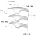
- FIGS. 14A-14C illustrate throat approximation variations similar to those shown in FIGS. 9A-9C but for a “thicker lip” with a narrower horn exit and higher horn frequency.
- FIG. 15 is a closer view of a throat approximation similar to the throat approximation shown in FIG. 14C .
- FIGS. 16A and 16B are front and back views of a low/mid frequency phase plug that is shaped to the surface of a woofer, including the nose cone of the woofer.
- FIG. 16A shows the rear of the phase plug.
- FIG. 16B shows the front of the phase plug where the slits converge at the rectangular diffraction slot.
- FIG. 17 illustrates the dimensions of a variation of the phase plug that shows the width of the compression areas including the rear of the phase plug.
- FIGS. 18A-18D conceptually illustrate a method of assembling the woofer, phase plug, and speaker gap standoff.
- FIGS. 19A-19J are drawings showing a method of assembling a diffraction baffle that includes a low/mid frequency compression plug, woofer standoff, and low/mid frequency horn lips.
- FIGS. 20A and 20B show variations in the construction of phase plugs for a low/mid frequency system.
- any of a variety of modifications in the number and dimensions of the channels of the phase plug can be utilized in accordance with embodiments of the invention as appropriate to the requirements of specific speaker assembly applications.
- FIG. 21 is a photograph of a prototype of a two way system with 180 degree high frequency and 180 degree low/mid frequency diffraction baffles with horns.
- the low frequency system contains a phase plug and approximated “flatted” lips.
- the system is a bass reflex woofer cabinet with a compression tweeter mounted on top.
- FIGS. 22A-22C is a photograph of a variation of a low/mid frequency diffraction baffle with phase plug and horn system.
- FIG. 22A shows the rear of the compression plug and phase plug slits for sound propagation. The standoff for the woofer is also shown.
- FIG. 22B is the same rear view but the compression plug is rotated 90 degrees for a different view of the profile of the compression plug.
- FIG. 22C is the front of the same system showing the approximated horns and a variation of the phase plug with an elongated tip. In this variation, the horn length is very short and the gap at the horn exit is the same as the height of the exit throat (slit height). As can readily be appreciated, many other variations are possible.
- FIG. 23 illustrates a speaker assembly including a single driver that acts as a direct radiator below a cutoff frequency and drives a diffraction baffle with horn above the cutoff frequency in accordance with an embodiment of the invention.
- FIG. 24 is a photograph of a speaker assembly including a single driver that acts as a direct radiator below a cutoff frequency and drives a diffraction baffle with horn above the cutoff frequency in accordance with an embodiment of the invention.
- FIG. 25 conceptually illustrates a three way speaker assembly in accordance with an embodiment of the invention.
- FIGS. 26A and 26B conceptually illustrate front and back views of a diffraction baffle with horn that can be utilized with a bass driver of a three way speaker assembly in accordance with an embodiment of the invention.
- FIG. 27 conceptually illustrates a three way speaker assembly in accordance with another embodiment of the invention.
- FIGS. 28 and 29 illustrate speaker assemblies including multiple drivers in accordance with various embodiments of the invention.
- FIG. 30 is a photograph of a two way speaker assembly in accordance with an embodiment of the invention.
- the speaker assembly includes one or more diffraction baffles with a baffle face having an opening, referred to as a diffraction slot, positioned over the corresponding speaker driver where substantially all of the audio energy (i.e., air pressure) generated from the front of the speaker driver exits through the opening in the diffraction baffle.
- the surrounding surfaces of the diffraction slot are sealed to the areas surrounding the speaker driver to ensure that the air pressure must exit through the diffraction slot.
- the opening is the exit of a phase plug portion of the diffraction baffle.
- the diffraction slot may be shaped as a rectangle, square, circle, oval, or other shape as appropriate to the particular application. In several embodiments discussed below, the diffraction slot is rectangular with a greater height dimension than width dimension.
- the wavefront When a wave passes through an opening in a barrier where the opening has a dimension greater than the wavelength, the wave typically passes directly through.
- the opening When the opening has a dimension equal to or smaller than the wavelength, the wavefront typically expands into an almost semicircular shape in the direction of that dimension.
- the portion of the wavefront closest to the edge of the opening rotates to become orthogonal or nearly orthogonal to the surface of the barrier at the exit of the opening before the wavefront progresses further outward way from the opening. This expansion and change in shape of a wavefront can be referred to as diffraction.
- a baffle face includes a diffraction slot having a first dimension equal to or smaller than the wavelength of a wave having a predetermined target frequency and a second dimension larger than the wavelength of a wave having the predetermined target frequency.
- the wavefront of a wave having a wavelength equal to or smaller than first dimension travelling through the slot can be modeled as a cylindrical surface at various distances progressing from the exit of the slot.
- a throat region at the exit of the slot includes a first throat surface and a second throat surface that bound the second dimension at the exit.
- Speaker drivers can include tweeters, mid-range drivers, and/or woofers as appropriate to a particular application.
- the speaker assembly incorporates a dual-baffle system driven by a tweeter and a woofer. Further embodiments include one or more phase plugs each positioned in front of a driver.
- the term woofer refers to a driver designed to generate low and/or mid-frequency sounds and a tweeter is a speaker designed to generate high-frequency sounds. Speakers that incorporate two drivers and crossover circuitry to provide each drive with an appropriate frequency range are often referred to as two-way speakers.
- the speaker assemblies incorporate a single driver or may include three or more drivers.
- the tweeter utilizes a compression driver.
- the tweeter is a direct radiating tweeter such as (but not limited to) a dome tweeter.
- the tweeter drives a wide dispersion diffraction baffle having a radius sufficiently large to support frequencies at the lower end of the operating frequency range of the tweeter.
- the throat of the diffraction baffle is configured to shape planar waves driven into the diffraction baffle by the tweeter to produce a cylindrical wavefront.
- the cylindrical wavefront is provided to a horn region of the diffraction baffle that expands exponentially. Shaping the wavefront in this way can increase the horizontal dispersion pattern of the diffraction baffle.
- Wavefront shaping in accordance with various embodiments of the invention is discussed further below.
- many of the horns described herein include exponential flares, horns having any of a variety of flares can be utilized in any of the embodiments described herein. Accordingly, the invention should not be limited to any specific horn flare configuration or class of horn flare configurations.
- some embodiments of a diffraction baffle do not utilize a horn. That is, a baffle face attached to and positioned over the compression driver is formed with a diffraction slot, but without horn elements that further interact with or influence waves emanating from the tweeter.
- the woofer utilizes a compression driver.
- the woofer diffraction baffle is configured to act as a direct radiator below the cutoff frequency of the diffraction baffle and is driven by the low/mid frequency driver of the woofer above the cutoff frequency. In this way, the length of the flare of the horn of the diffraction baffle (i.e. the distance from the throat of the horn to the lips or mouth of the horn) can be reduced relative to a horn that is driven by the low/mid frequency driver across the entire operating frequency range of the low/mid frequency compression driver.
- the low/mid frequency diffraction baffle achieves a wide dispersion pattern by changing the shape of the wavefronts of acoustic pressure waves driven into the throat of the diffraction baffle in a similar manner to that described above with respect to the tweeter diffraction baffle.
- a first direction e.g. vertical
- a second direction e.g.
- the throat can change the shape of the wavefronts of the acoustic pressure waves from planar wavefront to cylindrical wavefronts, thereby increasing the dispersion of the wavefronts as they propagate out.
- the wavefront can then be radiated by any of a variety of horn flares including (but not limited to) flat, linearly sloped, and/or exponentially shaped transitions from the throat of the diffraction baffle to the mouth of the horn portion.
- the specific flare shape used in the low/mid frequency horn typically depends upon the requirements of a given speaker assembly.
- some embodiments do not utilize a horn. That is, the baffle face attached to and positioned over the compression driver is formed with a diffraction slot without horn elements that further interact with or influence waves emanating from the woofer.
- the operation of the woofer as a direct radiator below a specific cutoff frequency results in the woofer having an uneven frequency response.
- the woofer benefits from an efficiency gain above the cutoff frequency provided by the diffraction baffle.
- the difference in efficiency between the direct radiating mode and the use of the diffraction baffle above the cutoff frequency is accommodated through the use of equalization.
- Frequencies below the frequency cutoff can be boosted and/or frequencies above the frequency cutoff can be attenuated.
- the equalization applied to the signal used to drive the woofer can be described by an equalization curve that is the inverse of the efficiency gain for the diffraction baffle at frequencies above the cutoff frequency.
- the speaker assemblies utilize phase plugs.
- phase plugs are utilized with one or both of the diffraction baffles.
- phase plugs can be utilized without a diffraction baffle.
- the phase plug utilized with the tweeter comprises multiple radial channels.
- the phase plug utilized in the low-mid frequency diffraction baffle is positioned close to the diaphragm of the low/mid frequency driver to achieve compression.
- the phase plug includes multiple channels that converge in a slot with a width configured to provide wide dispersion for frequencies including the highest frequencies within the operating range of the low/mid frequency driver.
- the specific structure of a phase plug used as a mechanical interface between a driver and a diffraction baffle is largely dependent upon the requirements of a specific speaker assembly.
- the dual baffle of the speaker generate a horizontal dispersion pattern greater than 95 degrees. In several embodiments, dual baffles of the speaker generate a horizontal dispersion pattern greater than 100 degrees. In certain embodiments, dual baffles of the speaker generate a 180 degree horizontal dispersion pattern. In certain embodiments, a diffraction baffle of a speaker assembly in accordance with an embodiment of the invention can generate a greater than 180 degree horizontal dispersion pattern.
- speaker assemblies in accordance with various embodiments of the invention can include any number of drivers including (but not limited to) a single driver, or three or more drivers. Specifically, mid-range drivers and/or additional types of speaker drivers may be utilized to produce sound of different frequency ranges from those discussed above. Speaker assemblies in accordance with various embodiments of the invention are discussed further below.
- the speaker assembly 100 includes an enclosure 102 (often referred to as a cabinet) that contains the drivers and electronics of the speaker assembly and a front 104 or baffle face of the diffraction baffle to which the dual horns 106 , 108 are integrally formed.
- the dual horns are constructed separately and affixed to the baffle face 104 .
- the 180 degree high frequency diffraction baffle 106 is positioned above the 180 degree low/mid frequency diffraction baffle 108 .
- the 180 degree low/mid frequency diffraction baffle 108 incorporates a phase plug 110 .
- the 180 degree low/mid frequency diffraction baffle 108 does not include a phase plug.
- the incorporation of a phase plug in either the low/mid or high frequency diffraction baffle can be beneficial in equalizing sound wave path lengths from the driver to the listener, to reduce the effect of cancellations and frequency response problems that can result from interfering audio waves having different path lengths.
- acceptable sound quality can be achieved by a diffraction baffle without the use of a phase plug and/or horn.
- the 180 degree high frequency diffraction baffle 106 is driven by a tweeter 112 .
- the tweeter is a compression driver.
- any of a variety of direct radiating high frequency drivers that may or may not utilize compression can be used to drive the high frequency diffraction baffle of the speaker assembly including (but not limited to) a dome tweeter.
- compression drivers and dome tweeters are that the vibrating member is typically stiffer in a compression driver and the compression driver incorporates a phase plug.
- compression drivers typically produce acoustic pressure waves having planar wavefronts that can be used to a feed a diffraction baffle.
- a dome tweeter by contrast is typically designed to work in free air and is often designed for greater excursion than is typical for a compression driver.
- Speaker assemblies in accordance with many embodiments of the invention can utilize dome tweeters in conjunction with diffraction baffles with entrance slits that provide little or mild non-distorting compression.
- speaker assemblies in accordance with various embodiments of the invention can utilize a dome tweeter in conjunction with a phase plug. Examples of various adaptors that can be utilized to interface a speaker driver with a baffle face are shown in FIGS.
- FIGS. 6C-6M and various phase plugs that can be utilized to interface a dome tweeter and a baffle face are shown in FIGS. 6N and 6O . Similar configurations can also be utilized in three way speaker assemblies that incorporate dome midrange drivers.
- the adaptor illustrated in FIGS. 6C-6D includes a circular entrance 602 that narrows to a smaller radius circular section 604 . This narrowing provides some amount of compression by reducing the surface area of a wavefront passing through. From the smaller radius section to the rectangular exit 606 , the surfaces are shaped to change from a circular shape to a rectangular shape to match the entrance of the diffraction slot. Through the shape-changing transition section, the surface is shaped to maintain the surface area of a wavefront to be constant as it progresses.
- the wavefront stays as a planar wave and changes its outer shape.
- the rectangular exit is 3 ⁇ 4′′ wide by 1′′ tall.
- the adaptor illustrated in FIGS. 6E-6F does not include a compression section. It includes an entrance 608 that approximates the shape of the speaker driver and a rectangular exit 610 to match the entrance of the diffraction slot. Through the shape-changing transition section, the surface is shaped to maintain the surface area of a wavefront to be constant as it progresses.
- the high frequency driver directs pressure waves into an initial stage or throat of the 180 degree high frequency diffraction baffle 106 .
- the throat 114 of the diffraction baffle narrows in a first dimension (vertical) and expands in a second dimension (horizontal).
- the changes in the two dimensions are controlled along the throat of the diffraction baffle so that the surface area of the wavefront as it is distorted within the throat of the diffraction baffle maintains a constant surface area.
- FIG. 4A illustrates a two-dimensional view of the shaping of a planar wavefront into a cylindrical wavefront by the diffraction slot and throat of a diffraction baffle.
- This cross-sectional view shows the width of the diffraction slot that is equal to or smaller than the wavelength of a predetermined target frequency.
- the arcs show the shape of a wavefront having a frequency at or lower than the predetermined target frequency at various distances as the wavefront progresses from the exit of the diffraction slot.
- FIG. 4B illustrates in three-dimensions the manner in which the shape of the diffraction slot and throat pinches the wavefront in a first direction and shapes the wavefront in a second direction to create a cylindrical wavefront having substantially the same surface area as the planar wave entering the horn.
- the shape of the throat changes the shape of the wavefront of a pressure wave entering the diffraction slot so that a planar wavefront provided to the diffraction slot is compressed in the first direction and expands in a second direction increasing the dispersion of the wavefront in the second direction to create a cylindrical wavefront (i.e. a wavefront that is a section of a cylinder).
- the two wedges illustrate an approximated upper throat surface that bounds the wavefront as it progresses through the throat region.
- a lower throat surface can mirror the shape of the upper throat surface.
- a sloped lower throat surface according to various embodiments of the invention can be seen in FIGS. 7, 9B, 12B , and 15 as the center portion of the diffraction baffle at the exit of the diffraction slot.
- the cylindrical wavefront feeds the flare of the horn portion of the diffraction baffle beyond the throat, which provides a wave dispersion pattern as the wavefront propagates.
- any of a variety of throat designs can be utilized in a diffraction baffle to shape the wavefronts of acoustic pressure waves as appropriate to the requirements of specific applications in accordance with embodiments of the invention.
- the waves may feed a horn portion of the diffraction baffle or the baffle may not include a horn.
- FIG. 6M A front view of a throat region 612 , baffle face 614 , diffraction slot 616 , and adapter portion 618 of a diffraction baffle in accordance with embodiments of the invention is illustrated in FIG. 6M .
- the vertical ridges protruding from the baffle face provide upper and lower throat surfaces 620 and 622 that bound the upper and lower sides of the exit of the diffraction slot 616 .
- an adapter portion 618 provides a circular entrance 624 that transitions to the rectangular diffraction slot 616 .
- the result is that the shape of the throat 114 of the 180 degree high frequency diffraction baffle 106 creates a 180 degree horizontal dispersion pattern.
- the throat 114 of the 180 degree high frequency diffraction baffle 106 transitions to an exponential region 116 in which the horn portion is shaped to enable the area of the wavefront to expand at an exponential rate.
- the exponential region 116 transitions to a flared horn mouth 118 from which high frequency acoustic pressure waves can radiate.
- the horn mouth 118 is designed for aesthetic effect.
- a horn mouth that is part of the exponential flare of the horn can be utilized.
- similar horns can be utilized to create a wide horizontal dispersion pattern that is less than 180 degrees.
- similar high frequency horns are used with speakers having horizontal dispersion patterns greater than 90 degrees.
- similar high frequency horns are used with speakers having horizontal dispersion patterns in the range of 95 degrees to 180 degrees.
- FIGS. 5, 6A, 6B, and 21 Additional examples of high frequency diffraction baffles that can be utilized in speaker assemblies in accordance with various embodiments of the invention are illustrated in FIGS. 5, 6A, 6B, and 21 .
- any of a variety of high frequency diffraction baffles that result in a desired dispersion pattern can be utilized as appropriate to the requirements of a specific speaker assembly applications including (but not limited to) diffraction baffles that incorporate phase plugs to increase the width of the dispersion pattern of the diffraction baffle in a manner similar to that discussed below with respect to the phase plug incorporated within the 180 degree low/mid frequency diffraction baffle illustrated in the speaker assembly shown in FIGS. 1-4 .
- horn portions of a diffraction baffle may be flat without any curvature such as in the embodiments illustrated in FIGS. 21 and 24 .
- the low/mid frequency driver 120 is a compression driver and the 180 degree low/mid frequency diffraction baffle 108 incorporates a phase plug 122 that is spaced a small gap 123 away from the low/mid frequency driver 120 .
- a phase plug acts as a mechanical interface between the low/mid frequency driver 120 and the 180 degree low/mid frequency diffraction baffle 108 .
- phase plugs are typically utilized to equalize sound wave path lengths from the driver to the listener, to reduce the effect of cancellations and frequency response problems that can result from interfering audio waves having different path lengths.
- phase plugs are utilized that include channels from the low/mid frequency driver to the throat of the low/mid frequency diffraction baffle.
- the phase plug is utilized as a mechanical interface to the low/mid frequency diffraction baffle and includes multiple channels that converge to a rectangular diffraction slot that is configured to drive acoustic pressure waves into the throat of the low/mid frequency diffraction baffle.
- the width of the diffraction slot to which the channels converge is typically determined based upon the high frequency cutoff of the frequency range of the woofer.
- a diffraction slot that is as tall as the diaphragm of the low/mid frequency compression driver can be utilized with the width of the slot tuned based upon the operating range of the low/mid frequency compression driver and the area of the diaphragm of the compression driver.
- a low/mid frequency driver with a 5 inch diameter can load a slot that is 2 inches wide and 6 inches high and achieve a 90 degree horizontal dispersion pattern around 6700 Hz and a significantly wider dispersion pattern at 3300 Hz, which is a good frequency for crossover between the woofer and the tweeter.
- the specific dimensions of the diffraction slot largely depend upon the requirements of particular applications.
- the dimensions of the phase plug typically depend upon the shape and excursion of the diaphragm of the compression driver.
- a compression driver with an 8 inch diameter diaphragm is utilized.
- the dimensions of the diaphragm are largely dependent upon the requirements of a specific speaker assembly application.
- a diffraction slot can be utilized as the output for acoustic waves from the speaker driver without a phase plug such as in the embodiments illustrated in FIGS. 6A-B and 24 .
- the diffraction slot can be dimensioned similarly as discussed above, where the width of the slot in the direction for wide dispersion is equal to the wavelength of the highest frequency (the target wavelength and target frequency) of the frequency band that it is designed for wide dispersion. Typically, this frequency band falls within the frequencies that the speaker driver produces. In several embodiments, the edges of the diffraction slot all fall within a single plane for the most ideal performance.
- phase plugs are described above with reference to FIGS. 1-4 any of a variety of phase plugs can be utilized in either the woofer or tweeter as appropriate to the specific requirements of a given speaker assembly application in accordance with embodiments of the invention.
- Various phase plugs that can be utilized as mechanical interfaces between low/mid frequency drivers and low/mid frequency diffraction baffles in accordance with embodiments of the invention are illustrated in FIGS. 16A, 16B, 17, 18A-18D, 19A-19J, 20A, 20B and 22A-22C .
- the specific phase plug design utilized is largely dependent upon the requirements of a given speaker assembly.
- the phase plug does not protrude beyond the exit of the diffraction slot.
- an acceptable audio quality can be obtained without the use of a phase plug and/or horn portion.
- the 180 degree low/mid frequency diffraction baffle 108 does not operate over the full operating frequency range of the low/mid frequency driver. Specifically, the 180 degree low/mid frequency diffraction baffle 108 behaves as a direct radiator below a cutoff frequency and operates as a horn above the cutoff frequency. In the illustrated embodiment, the cutoff frequency is above approximately 515 Hz. In many embodiments, diffraction baffles can be constructed with cutoff frequencies above approximately 350 Hz. By not utilizing the diffraction baffle to shape the wavefront of the acoustic pressure waves below the threshold frequency, the diffraction baffle can have a smaller form factor. The low/mid frequency diffraction baffle largely determines the overall size of the speaker assembly.
- Reducing the length of the diffraction baffle including a horn portion increases the cutoff frequency of the diffraction baffle. Therefore, the ability to drive the low/mid frequency driver below the cutoff frequency of the low/mid frequency diffraction baffle can be a key element of achieving a smaller form factor than typical speaker assemblies that utilize low/mid frequency diffraction baffles.
- the shape of the 180 degree low/mid frequency diffraction baffle 108 is illustrated.
- the shape of the 180 degree low/mid frequency diffraction baffle 108 is similar to that of the 180 degree high frequency diffraction baffle 106 of the speaker assembly 100 described above.
- the throat of the 180 degree low/mid frequency diffraction baffle 108 compresses the wavefront of acoustic pressure waves driven into the throat of the diffraction baffle in a first direction (i.e. vertical) while allowing the wavefront to expand in a second direction (i.e. horizontal).
- the 180 degree low/mid frequency diffraction baffle includes an exponential 126 transition from the throat 124 of the diffraction baffle to the mouth of the horn portion.
- an exponential transition is shown, any of a variety of transitions can be utilized from the throat to the mouth of the horn including (but not limited to) a flat transition, a linear sloped transition, and/or any other transition appropriate to the requirements of a specific application.
- the specific flare utilized within the horn is typically influenced by a lower operational frequency cutoff of the horn and/or the desired audio quality of the speaker assembly.
- equalization circuitry can be utilized to perform a combination of boosting of frequencies below a frequency cutoff and/or attenuating frequencies above the frequency cutoff.
- the equalization applied to the signal used to drive the woofer can be described by an equalization curve that is the inverse of the efficiency gain for the diffraction baffle at frequencies above the cutoff frequency.
- An exemplary equalization curve is illustrated in FIG. 4C .
- the specific equalization curve applied by equalization circuitry typically depends upon the frequency response of a specific woofer and horn combination.
- any of a variety of horns that are configured to be driven by a low/mid frequency driver can be utilized in speaker assemblies in accordance with embodiments of the invention.
- Various low/mid frequency diffraction baffle designs in accordance with a number of embodiments of the invention are shown in FIGS. 5A, 5B, 7-15, and 21 .
- FIGS. 23 and 24 illustrated speaker assemblies including a single driver and FIGS. 25-30 include speakers incorporating three or more drivers.
- the orientation of elements can be changed, e.g., by rotation, translation, and/or direction, as appropriate to a particular application in accordance with embodiments of the invention.
- a diffraction baffle may include any number of throat surfaces positioned in any of a variety of locations with respect to the diffraction slot in the diffraction baffle.
- Some embodiments include a left throat surface and a right throat surface instead of top and bottom throat surfaces. While the discussion above utilizes compression drivers, dome or cone or any of a variety of other types of drivers may be utilized to produce sound in various frequency ranges as appropriate to a particular application. Accordingly, the scope of the invention should be determined not by the embodiments illustrated, but by the claims made based upon the disclosure contained herein and their equivalents.
Landscapes
- Physics & Mathematics (AREA)
- Engineering & Computer Science (AREA)
- Acoustics & Sound (AREA)
- Signal Processing (AREA)
- Health & Medical Sciences (AREA)
- Otolaryngology (AREA)
- Details Of Audible-Bandwidth Transducers (AREA)
Abstract
Description
Claims (36)
Priority Applications (1)
| Application Number | Priority Date | Filing Date | Title |
|---|---|---|---|
| US15/361,342 US10547934B2 (en) | 2015-11-24 | 2016-11-25 | Speaker assemblies with wide dispersion patterns |
Applications Claiming Priority (2)
| Application Number | Priority Date | Filing Date | Title |
|---|---|---|---|
| US201562259597P | 2015-11-24 | 2015-11-24 | |
| US15/361,342 US10547934B2 (en) | 2015-11-24 | 2016-11-25 | Speaker assemblies with wide dispersion patterns |
Publications (2)
| Publication Number | Publication Date |
|---|---|
| US20170150251A1 US20170150251A1 (en) | 2017-05-25 |
| US10547934B2 true US10547934B2 (en) | 2020-01-28 |
Family
ID=58721478
Family Applications (1)
| Application Number | Title | Priority Date | Filing Date |
|---|---|---|---|
| US15/361,342 Active US10547934B2 (en) | 2015-11-24 | 2016-11-25 | Speaker assemblies with wide dispersion patterns |
Country Status (1)
| Country | Link |
|---|---|
| US (1) | US10547934B2 (en) |
Cited By (1)
| Publication number | Priority date | Publication date | Assignee | Title |
|---|---|---|---|---|
| USD1032563S1 (en) * | 2022-10-31 | 2024-06-25 | Phillips Design Company Llc | Audio cabinet |
Families Citing this family (3)
| Publication number | Priority date | Publication date | Assignee | Title |
|---|---|---|---|---|
| USD886764S1 (en) | 2016-11-09 | 2020-06-09 | Lloyd Baggs Innovations, Llc | Speaker |
| US10587951B1 (en) * | 2018-09-13 | 2020-03-10 | Plantronics, Inc. | Equipment including down-firing speaker |
| EP4165625B1 (en) * | 2020-06-10 | 2024-08-28 | Dolby Laboratories Licensing Corporation | Asymmetrical acoustic horn |
Citations (35)
| Publication number | Priority date | Publication date | Assignee | Title |
|---|---|---|---|---|
| US3483945A (en) * | 1967-08-28 | 1969-12-16 | Musitronic Inc | Omnidirectional sound system |
| US4310065A (en) * | 1979-05-11 | 1982-01-12 | Chromalloy Electronics Corporation | Radial horn |
| US4923031A (en) * | 1986-02-26 | 1990-05-08 | Electro-Voice, Incorporated | High output loudspeaker system |
| USD328462S (en) | 1990-06-04 | 1992-08-04 | Infinity Systems, Inc. | Speaker |
| USD355914S (en) | 1992-08-21 | 1995-02-28 | Canon Audio Limited | Loudspeaker |
| US5402502A (en) | 1992-08-20 | 1995-03-28 | Canon Audio Limited | Sound output system |
| USD376364S (en) | 1994-04-22 | 1996-12-10 | Canon Audio Limited | Loudspeaker |
| US5715322A (en) * | 1992-08-25 | 1998-02-03 | Toa Corporation | Throat device interconnecting a plurality of drive units and a horn |
| USD397117S (en) | 1997-01-06 | 1998-08-18 | Platinum Audio, Ltd. | Audio speaker |
| USD429235S (en) | 1995-05-17 | 2000-08-08 | Bose Corporation | Loudspeaker |
| US6112847A (en) | 1999-03-15 | 2000-09-05 | Clair Brothers Audio Enterprises, Inc. | Loudspeaker with differentiated energy distribution in vertical and horizontal planes |
| USD450778S1 (en) | 2000-07-31 | 2001-11-20 | Harman International Industries, Incorporated | Radiation boundary integrator for a loudspeaker system |
| USD470474S1 (en) | 2001-10-31 | 2003-02-18 | Sony Corporation | Speaker box |
| US20030209384A1 (en) * | 2002-05-09 | 2003-11-13 | Dalbec Richard H. | Loudspeaker system with common low and high frequency horn mounting |
| US6658128B1 (en) * | 1998-04-30 | 2003-12-02 | Toa Corporation | Horn loudspeaker |
| US20030228021A1 (en) * | 2002-06-06 | 2003-12-11 | Fabrica Italiana Accumulatori Motocarri Montecchio F.I.A.M.M.S.P.A. | Acoustic-signal emitting device for vehicles |
| USD519105S1 (en) | 2005-01-14 | 2006-04-18 | Sony Corporation | Speaker |
| USD567214S1 (en) | 2006-01-04 | 2008-04-22 | Tymphany Corporation | Loudspeaker |
| USD573585S1 (en) | 2007-05-25 | 2008-07-22 | Theodore George Keffalo | Loudspeaker |
| US20090046875A1 (en) * | 2005-12-22 | 2009-02-19 | Tadashi Masuda | Speaker device |
| USD592645S1 (en) | 2008-01-14 | 2009-05-19 | Sony Corporation | Speaker box |
| USD609217S1 (en) | 2009-03-04 | 2010-02-02 | RCF S.p.A. | Loudspeaker |
| US7802650B2 (en) * | 2008-07-09 | 2010-09-28 | John Kevin Bartlett | Combination midrange and high frequency horn |
| US8181736B2 (en) | 2008-08-14 | 2012-05-22 | Harman International Industries, Incorporated | Phase plug and acoustic lens for direct radiating loudspeaker |
| USD671525S1 (en) | 2011-01-27 | 2012-11-27 | Samsung Electronics Co., Ltd. | Speaker |
| USD671526S1 (en) | 2011-02-21 | 2012-11-27 | Samsung Electronics Co., Ltd. | Speaker |
| USD682250S1 (en) | 2011-08-31 | 2013-05-14 | RCF S.p.A. | Amplifier |
| USD691591S1 (en) | 2012-03-14 | 2013-10-15 | Harman International Industries, Incorporated | Loudspeaker |
| USD698335S1 (en) | 2012-11-09 | 2014-01-28 | Yamaha Corporation | Speaker |
| US20140112513A1 (en) * | 2012-10-22 | 2014-04-24 | Jazz Hipster Corporation | Horn Amplifier |
| US20140119588A1 (en) * | 2012-10-26 | 2014-05-01 | Emanuel LaCarrubba | Acoustical transverse horn for controlled horizontal and vertical sound dispersion |
| US20140270309A1 (en) * | 2013-03-15 | 2014-09-18 | Loud Technologies Inc | Speaker |
| US9111521B2 (en) * | 2009-09-11 | 2015-08-18 | Bose Corporation | Modular acoustic horns and horn arrays |
| USD741795S1 (en) | 2013-10-25 | 2015-10-27 | Milwaukee Electric Tool Corporation | Radio charger |
| USD769214S1 (en) | 2014-11-14 | 2016-10-18 | Bose Corporation | Speaker |
-
2016
- 2016-11-25 US US15/361,342 patent/US10547934B2/en active Active
Patent Citations (36)
| Publication number | Priority date | Publication date | Assignee | Title |
|---|---|---|---|---|
| US3483945A (en) * | 1967-08-28 | 1969-12-16 | Musitronic Inc | Omnidirectional sound system |
| US4310065A (en) * | 1979-05-11 | 1982-01-12 | Chromalloy Electronics Corporation | Radial horn |
| US4923031A (en) * | 1986-02-26 | 1990-05-08 | Electro-Voice, Incorporated | High output loudspeaker system |
| USD328462S (en) | 1990-06-04 | 1992-08-04 | Infinity Systems, Inc. | Speaker |
| US5402502A (en) | 1992-08-20 | 1995-03-28 | Canon Audio Limited | Sound output system |
| USD355914S (en) | 1992-08-21 | 1995-02-28 | Canon Audio Limited | Loudspeaker |
| US5715322A (en) * | 1992-08-25 | 1998-02-03 | Toa Corporation | Throat device interconnecting a plurality of drive units and a horn |
| USD376364S (en) | 1994-04-22 | 1996-12-10 | Canon Audio Limited | Loudspeaker |
| USD429235S (en) | 1995-05-17 | 2000-08-08 | Bose Corporation | Loudspeaker |
| USD397117S (en) | 1997-01-06 | 1998-08-18 | Platinum Audio, Ltd. | Audio speaker |
| US6658128B1 (en) * | 1998-04-30 | 2003-12-02 | Toa Corporation | Horn loudspeaker |
| US6112847A (en) | 1999-03-15 | 2000-09-05 | Clair Brothers Audio Enterprises, Inc. | Loudspeaker with differentiated energy distribution in vertical and horizontal planes |
| USD450778S1 (en) | 2000-07-31 | 2001-11-20 | Harman International Industries, Incorporated | Radiation boundary integrator for a loudspeaker system |
| USD470474S1 (en) | 2001-10-31 | 2003-02-18 | Sony Corporation | Speaker box |
| US20030209384A1 (en) * | 2002-05-09 | 2003-11-13 | Dalbec Richard H. | Loudspeaker system with common low and high frequency horn mounting |
| US20030228021A1 (en) * | 2002-06-06 | 2003-12-11 | Fabrica Italiana Accumulatori Motocarri Montecchio F.I.A.M.M.S.P.A. | Acoustic-signal emitting device for vehicles |
| USD519105S1 (en) | 2005-01-14 | 2006-04-18 | Sony Corporation | Speaker |
| US20090046875A1 (en) * | 2005-12-22 | 2009-02-19 | Tadashi Masuda | Speaker device |
| USD567214S1 (en) | 2006-01-04 | 2008-04-22 | Tymphany Corporation | Loudspeaker |
| USD573585S1 (en) | 2007-05-25 | 2008-07-22 | Theodore George Keffalo | Loudspeaker |
| USD592645S1 (en) | 2008-01-14 | 2009-05-19 | Sony Corporation | Speaker box |
| US7802650B2 (en) * | 2008-07-09 | 2010-09-28 | John Kevin Bartlett | Combination midrange and high frequency horn |
| US8181736B2 (en) | 2008-08-14 | 2012-05-22 | Harman International Industries, Incorporated | Phase plug and acoustic lens for direct radiating loudspeaker |
| US20120279797A1 (en) | 2008-08-14 | 2012-11-08 | Harman International Industries, Incorporated | Phase plug and acoustic lens for direct radiating loudspeaker |
| USD609217S1 (en) | 2009-03-04 | 2010-02-02 | RCF S.p.A. | Loudspeaker |
| US9111521B2 (en) * | 2009-09-11 | 2015-08-18 | Bose Corporation | Modular acoustic horns and horn arrays |
| USD671525S1 (en) | 2011-01-27 | 2012-11-27 | Samsung Electronics Co., Ltd. | Speaker |
| USD671526S1 (en) | 2011-02-21 | 2012-11-27 | Samsung Electronics Co., Ltd. | Speaker |
| USD682250S1 (en) | 2011-08-31 | 2013-05-14 | RCF S.p.A. | Amplifier |
| USD691591S1 (en) | 2012-03-14 | 2013-10-15 | Harman International Industries, Incorporated | Loudspeaker |
| US20140112513A1 (en) * | 2012-10-22 | 2014-04-24 | Jazz Hipster Corporation | Horn Amplifier |
| US20140119588A1 (en) * | 2012-10-26 | 2014-05-01 | Emanuel LaCarrubba | Acoustical transverse horn for controlled horizontal and vertical sound dispersion |
| USD698335S1 (en) | 2012-11-09 | 2014-01-28 | Yamaha Corporation | Speaker |
| US20140270309A1 (en) * | 2013-03-15 | 2014-09-18 | Loud Technologies Inc | Speaker |
| USD741795S1 (en) | 2013-10-25 | 2015-10-27 | Milwaukee Electric Tool Corporation | Radio charger |
| USD769214S1 (en) | 2014-11-14 | 2016-10-18 | Bose Corporation | Speaker |
Non-Patent Citations (28)
| Title |
|---|
| "Acasa Boxe de centru", Yamaha Shop, Dec. 14, 2015, retrieved from http://yamahashop.xhost.ro/Boxe_de_centru.htm on Aug. 23, 2019, 29 pages. |
| "Addition No. Fourteen Loudspeaker System Types", The PA Bible, Dec. 14, 2015, http://www.datalinkplus.com/procomm/BASICTR/PABBLWEB/14LoudspeakerSytemTypes.pdf, 4 pages. |
| "Altec Lansing Voice of the Theatre (VOTT)", Great Plains Audio, Jul. 1, 2017, retrieved from https://greatplainsaudio.com/altec-lansing-library/altec-lansing-voice-theatre-vott/ on Aug. 29, 2019, 2 pages. |
| "Avantgarde Acoustic Adric Technology", Purity Meets Performance, Avantgarde Acoustic, Dec. 14, 2015, 4 pages. |
| "Avantgarde Acoustic Horn Technology Video", YouTube, May 31, 2011, retrieved on https://www.youtube.com/watch?v=kPywOtjXJ10 on May 13, 2019, 3 pages. |
| "Caste Speakers", Worldwide Wholesales, Nov. 4, 2016, retrieved from http://web.archive.org/web/20161104091154/https:/worldwidewholesales.com/technologies/casta-speakers! on Aug. 22, 2019, 4 pages. |
| "Horn-Loaded Standard Dome Tweeters, p. 1", diyAudio, Dec. 17, 2006, retrieved from https://www.diyaudio.com/forums/multi-way/92375-horn-loading-standard-dome-tweeters.html on May 13, 2019, 5 pages. |
| "Horn-Loaded Standard Dome Tweeters, p. 2", diyAudio, Dec. 17, 2006, retrieved from https://www.diyaudio.com/forums/multi-way/92375-horn-loading-standard-dome-tweeters-2.html?s=35002968a505625252fa77e55194ce9f on May 13, 2019, 3 pages. |
| "HR4 Studio Monitors", OceanWay Audio, Oct. 27, 2015, retrieved from https://oceanwayaudio.com/hr4/ on May 13, 2019, 7 pages. |
| "Loudspeakers CBR Series", Yamaha, Nov. 21, 2015, retrieved from http://web.archive.org/web/20151121182448/http:/www.yamahaproaudio.com/global/en/products/speakers/cbr/features.jsp on Aug. 23, 2019, 2 pages. |
| "Low Frequency Enclosures", JBL, Dec. 14, 2015, http://www.jblpro.com/pub/obsolete/Low_Frequency_Enclosures2.pdf, 6 pages. |
| "Triangle Signature Delta Tower Speaker Overview", Mar. 10, 2015, retrieved on http://forums.audioholics.com/forums/threads/triangle-signature-delta-tower-speakeroverview.93945/ on May 13, 2019, 7 pages. |
| "Vifa, BC25SC06", Meniscus Audio, Dec. 14, 2015, retrieved from https://meniscusaudio.com/product/vifa-bc25sc06/ on Aug. 29, 2019, 4 pages. |
| "Voice of the Theatre", Altec Lansing, Jan. 1, 1983, retrieved from https://greatplainsaudio.com/wp-content/uploads/2017/07/VOTT.1983.pdf on Aug. 29, 2019, 15 pages. |
| "Wave Diffraction", University of Salford Manchester, http://www.acoustics.salford.ac.uk/feschools/waves/diffract3.php, dated Nov. 22, 2016, 5 pages. |
| Burnett, John, "Compression drivers", Dec. 9, 2008, retrieved from http://education.lenardaudio.com/en/07_horns_2.html on May 13, 2019, 6 pages. |
| Day, Jeff, "The Tao of Tannoy: The Westminster Royal Special Edition Loudspeakers", Positive Feedback, Issue 49, May 2010, retrieved on http://www.positive-feedback.com/Issue49/tannoy.htm on May 13, 2019, 24 pages. |
| Gravesen, Troels, "Vifa C17-11, Monacor DT300+waveguide", 2010, retrieved from http://www.troelsgravesen.dk/C17_II.htm on May 13, 2019, 11 pages. |
| Heutschi, Kurt, "Acoustics II: electrical-mechanical-acoustical analogies", Swiss Federal Institute of Technology Zurich, Jan. 18, 2013, 91 pages. |
| Heutschi, Kurt, "Acoustics II: loudspeakers", Swiss Federal Institute of Technology Zurich, Jan. 18, 2013, 120 pages. |
| Heutschi, Kurt, "Practical course: Loudspeakers", Acoustics II, Feb. 22, 2012, pp. 1-7. |
| http://redspade-audio.blogspot.com/2013/07/altec-a7-voice-of-theatre-hornsmeasured.html, Dec. 14, 2015, (web page no longer active, archive copy cannot be found). |
| http://speakeraddict.com/mid-high-frequency/horn-tweeters/vifa-horn-tweeter-1-domebc25sc06-04ohm-high-efficiency.html, Dec. 14, 2015, (web page no. longer active, archive copy cannot be found). |
| http://www.teufelaudio.com/blog/audio-knowledge/3-common-types-of-loudspeakerdriver-design/, Dec. 14, 2015, (web page no. longer active, archive copy cannot be found). |
| Kolbrek, Bjorn, "Horn Theory: An Introduction, Part 1", audioXpress, 2008, https://www.grc.com/acoustics/an-introduction-to-horn-theory.pdf, pp. 1-17. |
| Krutke, John, "What happens when you horn load a dome tweeter?", Zaph Audio, May 31, 2005, retrieved from http://www.zaphaudio.com/hornconversion.html on May 13, 2019, 8 pages |
| Micallef, Ken, "Orangutan O/93 Loudspeakers", Positive Feedback, Sep. 2014, Issue 75, retrieved from http://www.positive- feedback.com/Issue75/devore_orangutan.htm on May 13, 2019, 15 pages. |
| White, Robert C., "Practical DIY Waveguides—Part 3", Nov. 3, 2006, retrieved from http://sound.whsites.net/articles/waveguides3.htm on May 13, 2019, 9 pages. |
Cited By (1)
| Publication number | Priority date | Publication date | Assignee | Title |
|---|---|---|---|---|
| USD1032563S1 (en) * | 2022-10-31 | 2024-06-25 | Phillips Design Company Llc | Audio cabinet |
Also Published As
| Publication number | Publication date |
|---|---|
| US20170150251A1 (en) | 2017-05-25 |
Similar Documents
| Publication | Publication Date | Title |
|---|---|---|
| JP5662462B2 (en) | Omnidirectional speaker | |
| EP3755003B1 (en) | Multi-driver acoustic horn for horizontal beam control | |
| US9706289B2 (en) | Loudspeaker with improved directional behavior and reduction of acoustical interference | |
| EP3135043B1 (en) | Coaxial loudspeaker apparatus | |
| EP3395079B1 (en) | Mitigating effects of cavity resonance in speakers | |
| EP1333698B1 (en) | Directional loudspeaker unit | |
| US10785560B2 (en) | Waveguide for a height channel in a speaker | |
| EP3338460B1 (en) | An loudspeaker comprising a horn and a method for creating uniform sound using loudspeaker | |
| US20170251296A1 (en) | Loudspeaker with narrow dispersion | |
| US10547934B2 (en) | Speaker assemblies with wide dispersion patterns | |
| EP1827056A1 (en) | Speaker system with broad directivity | |
| EP3466108B1 (en) | Baffle for line array loudspeaker | |
| EP3138299B1 (en) | Multiple aperture device for low-frequency line arrays | |
| EP3932087B1 (en) | Acoustic reflector for height channel speaker | |
| US11490194B1 (en) | Omnidirectional speaker with an inverted dome diaphragm and asymmetric vertical directivity response | |
| GB2546067A (en) | Loudspeaker | |
| CN108605182A (en) | Conformal adapters for diffractive slots in loudspeakers | |
| CN112544087B (en) | Speaker system with multi-plane, nested, folded horns | |
| US20070058830A1 (en) | Contoured passive radiator and loudspeaker incorporating same | |
| US10341761B2 (en) | Acoustic waveguide for audio speaker | |
| KR20190062144A (en) | Loudspeaker and sound outputting apparatus having the same | |
| CN120935497A (en) | Mid-and tweeter assembly | |
| HK1171892A (en) | Omnidirectional speaker |
Legal Events
| Date | Code | Title | Description |
|---|---|---|---|
| AS | Assignment |
Owner name: LLOYD BAGGS INNOVATIONS, LLC, CALIFORNIA Free format text: ASSIGNMENT OF ASSIGNORS INTEREST;ASSIGNORS:BAGGS, LLOYD;LINN, THOMAS;REEL/FRAME:044733/0664 Effective date: 20180118 Owner name: L.R. BAGGS CORPORATION, CALIFORNIA Free format text: ASSIGNMENT OF ASSIGNORS INTEREST;ASSIGNOR:HENRICKSEN, CLIFFORD A.;REEL/FRAME:044733/0647 Effective date: 20171121 Owner name: LLOYD BAGGS INNOVATIONS, LLC, CALIFORNIA Free format text: ASSIGNMENT OF ASSIGNORS INTEREST;ASSIGNOR:L.R. BAGGS CORPORATION;REEL/FRAME:044733/0652 Effective date: 20180118 |
|
| STPP | Information on status: patent application and granting procedure in general |
Free format text: AWAITING TC RESP., ISSUE FEE NOT PAID |
|
| STPP | Information on status: patent application and granting procedure in general |
Free format text: NOTICE OF ALLOWANCE MAILED -- APPLICATION RECEIVED IN OFFICE OF PUBLICATIONS |
|
| STPP | Information on status: patent application and granting procedure in general |
Free format text: DOCKETED NEW CASE - READY FOR EXAMINATION |
|
| STPP | Information on status: patent application and granting procedure in general |
Free format text: NOTICE OF ALLOWANCE MAILED -- APPLICATION RECEIVED IN OFFICE OF PUBLICATIONS |
|
| STPP | Information on status: patent application and granting procedure in general |
Free format text: AWAITING TC RESP, ISSUE FEE PAYMENT VERIFIED |
|
| STCF | Information on status: patent grant |
Free format text: PATENTED CASE |
|
| MAFP | Maintenance fee payment |
Free format text: PAYMENT OF MAINTENANCE FEE, 4TH YR, SMALL ENTITY (ORIGINAL EVENT CODE: M2551); ENTITY STATUS OF PATENT OWNER: SMALL ENTITY Year of fee payment: 4 |