US10544785B2 - Scroll compressor with a locating crankshaft - Google Patents
Scroll compressor with a locating crankshaft Download PDFInfo
- Publication number
- US10544785B2 US10544785B2 US15/496,001 US201715496001A US10544785B2 US 10544785 B2 US10544785 B2 US 10544785B2 US 201715496001 A US201715496001 A US 201715496001A US 10544785 B2 US10544785 B2 US 10544785B2
- Authority
- US
- United States
- Prior art keywords
- bearing
- locating
- scroll
- face
- disk
- Prior art date
- Legal status (The legal status is an assumption and is not a legal conclusion. Google has not performed a legal analysis and makes no representation as to the accuracy of the status listed.)
- Active, expires
Links
- 230000005540 biological transmission Effects 0.000 claims description 27
- 238000000034 method Methods 0.000 description 11
- 230000000694 effects Effects 0.000 description 7
- 238000007906 compression Methods 0.000 description 6
- 230000006835 compression Effects 0.000 description 4
- 230000008901 benefit Effects 0.000 description 3
- 238000004519 manufacturing process Methods 0.000 description 2
- 238000005259 measurement Methods 0.000 description 2
- 238000003825 pressing Methods 0.000 description 2
- 238000005452 bending Methods 0.000 description 1
- 230000009286 beneficial effect Effects 0.000 description 1
- 238000004134 energy conservation Methods 0.000 description 1
- 230000017525 heat dissipation Effects 0.000 description 1
- 238000009434 installation Methods 0.000 description 1
- 239000013589 supplement Substances 0.000 description 1
Images


Classifications
-
- F—MECHANICAL ENGINEERING; LIGHTING; HEATING; WEAPONS; BLASTING
- F04—POSITIVE - DISPLACEMENT MACHINES FOR LIQUIDS; PUMPS FOR LIQUIDS OR ELASTIC FLUIDS
- F04C—ROTARY-PISTON, OR OSCILLATING-PISTON, POSITIVE-DISPLACEMENT MACHINES FOR LIQUIDS; ROTARY-PISTON, OR OSCILLATING-PISTON, POSITIVE-DISPLACEMENT PUMPS
- F04C18/00—Rotary-piston pumps specially adapted for elastic fluids
- F04C18/02—Rotary-piston pumps specially adapted for elastic fluids of arcuate-engagement type, i.e. with circular translatory movement of co-operating members, each member having the same number of teeth or tooth-equivalents
- F04C18/0207—Rotary-piston pumps specially adapted for elastic fluids of arcuate-engagement type, i.e. with circular translatory movement of co-operating members, each member having the same number of teeth or tooth-equivalents both members having co-operating elements in spiral form
- F04C18/0215—Rotary-piston pumps specially adapted for elastic fluids of arcuate-engagement type, i.e. with circular translatory movement of co-operating members, each member having the same number of teeth or tooth-equivalents both members having co-operating elements in spiral form where only one member is moving
-
- F—MECHANICAL ENGINEERING; LIGHTING; HEATING; WEAPONS; BLASTING
- F04—POSITIVE - DISPLACEMENT MACHINES FOR LIQUIDS; PUMPS FOR LIQUIDS OR ELASTIC FLUIDS
- F04C—ROTARY-PISTON, OR OSCILLATING-PISTON, POSITIVE-DISPLACEMENT MACHINES FOR LIQUIDS; ROTARY-PISTON, OR OSCILLATING-PISTON, POSITIVE-DISPLACEMENT PUMPS
- F04C29/00—Component parts, details or accessories of pumps or pumping installations, not provided for in groups F04C18/00 - F04C28/00
- F04C29/0042—Driving elements, brakes, couplings, transmissions specially adapted for pumps
- F04C29/005—Means for transmitting movement from the prime mover to driven parts of the pump, e.g. clutches, couplings, transmissions
- F04C29/0057—Means for transmitting movement from the prime mover to driven parts of the pump, e.g. clutches, couplings, transmissions for eccentric movement
-
- F—MECHANICAL ENGINEERING; LIGHTING; HEATING; WEAPONS; BLASTING
- F01—MACHINES OR ENGINES IN GENERAL; ENGINE PLANTS IN GENERAL; STEAM ENGINES
- F01C—ROTARY-PISTON OR OSCILLATING-PISTON MACHINES OR ENGINES
- F01C17/00—Arrangements for drive of co-operating members, e.g. for rotary piston and casing
- F01C17/06—Arrangements for drive of co-operating members, e.g. for rotary piston and casing using cranks, universal joints or similar elements
- F01C17/063—Arrangements for drive of co-operating members, e.g. for rotary piston and casing using cranks, universal joints or similar elements with only rolling movement
-
- F—MECHANICAL ENGINEERING; LIGHTING; HEATING; WEAPONS; BLASTING
- F04—POSITIVE - DISPLACEMENT MACHINES FOR LIQUIDS; PUMPS FOR LIQUIDS OR ELASTIC FLUIDS
- F04C—ROTARY-PISTON, OR OSCILLATING-PISTON, POSITIVE-DISPLACEMENT MACHINES FOR LIQUIDS; ROTARY-PISTON, OR OSCILLATING-PISTON, POSITIVE-DISPLACEMENT PUMPS
- F04C29/00—Component parts, details or accessories of pumps or pumping installations, not provided for in groups F04C18/00 - F04C28/00
- F04C29/04—Heating; Cooling; Heat insulation
-
- F—MECHANICAL ENGINEERING; LIGHTING; HEATING; WEAPONS; BLASTING
- F16—ENGINEERING ELEMENTS AND UNITS; GENERAL MEASURES FOR PRODUCING AND MAINTAINING EFFECTIVE FUNCTIONING OF MACHINES OR INSTALLATIONS; THERMAL INSULATION IN GENERAL
- F16C—SHAFTS; FLEXIBLE SHAFTS; ELEMENTS OR CRANKSHAFT MECHANISMS; ROTARY BODIES OTHER THAN GEARING ELEMENTS; BEARINGS
- F16C3/00—Shafts; Axles; Cranks; Eccentrics
- F16C3/04—Crankshafts, eccentric-shafts; Cranks, eccentrics
- F16C3/06—Crankshafts
- F16C3/10—Crankshafts assembled of several parts, e.g. by welding by crimping
-
- F—MECHANICAL ENGINEERING; LIGHTING; HEATING; WEAPONS; BLASTING
- F16—ENGINEERING ELEMENTS AND UNITS; GENERAL MEASURES FOR PRODUCING AND MAINTAINING EFFECTIVE FUNCTIONING OF MACHINES OR INSTALLATIONS; THERMAL INSULATION IN GENERAL
- F16C—SHAFTS; FLEXIBLE SHAFTS; ELEMENTS OR CRANKSHAFT MECHANISMS; ROTARY BODIES OTHER THAN GEARING ELEMENTS; BEARINGS
- F16C9/00—Bearings for crankshafts or connecting-rods; Attachment of connecting-rods
- F16C9/02—Crankshaft bearings
- F16C9/03—Arrangements for adjusting play
-
- F—MECHANICAL ENGINEERING; LIGHTING; HEATING; WEAPONS; BLASTING
- F04—POSITIVE - DISPLACEMENT MACHINES FOR LIQUIDS; PUMPS FOR LIQUIDS OR ELASTIC FLUIDS
- F04C—ROTARY-PISTON, OR OSCILLATING-PISTON, POSITIVE-DISPLACEMENT MACHINES FOR LIQUIDS; ROTARY-PISTON, OR OSCILLATING-PISTON, POSITIVE-DISPLACEMENT PUMPS
- F04C2230/00—Manufacture
- F04C2230/60—Assembly methods
- F04C2230/603—Centering; Aligning
-
- F—MECHANICAL ENGINEERING; LIGHTING; HEATING; WEAPONS; BLASTING
- F04—POSITIVE - DISPLACEMENT MACHINES FOR LIQUIDS; PUMPS FOR LIQUIDS OR ELASTIC FLUIDS
- F04C—ROTARY-PISTON, OR OSCILLATING-PISTON, POSITIVE-DISPLACEMENT MACHINES FOR LIQUIDS; ROTARY-PISTON, OR OSCILLATING-PISTON, POSITIVE-DISPLACEMENT PUMPS
- F04C2240/00—Components
- F04C2240/50—Bearings
-
- F—MECHANICAL ENGINEERING; LIGHTING; HEATING; WEAPONS; BLASTING
- F04—POSITIVE - DISPLACEMENT MACHINES FOR LIQUIDS; PUMPS FOR LIQUIDS OR ELASTIC FLUIDS
- F04C—ROTARY-PISTON, OR OSCILLATING-PISTON, POSITIVE-DISPLACEMENT MACHINES FOR LIQUIDS; ROTARY-PISTON, OR OSCILLATING-PISTON, POSITIVE-DISPLACEMENT PUMPS
- F04C2240/00—Components
- F04C2240/60—Shafts
- F04C2240/601—Shaft flexion
-
- F—MECHANICAL ENGINEERING; LIGHTING; HEATING; WEAPONS; BLASTING
- F04—POSITIVE - DISPLACEMENT MACHINES FOR LIQUIDS; PUMPS FOR LIQUIDS OR ELASTIC FLUIDS
- F04C—ROTARY-PISTON, OR OSCILLATING-PISTON, POSITIVE-DISPLACEMENT MACHINES FOR LIQUIDS; ROTARY-PISTON, OR OSCILLATING-PISTON, POSITIVE-DISPLACEMENT PUMPS
- F04C2240/00—Components
- F04C2240/80—Other components
- F04C2240/802—Liners
-
- F—MECHANICAL ENGINEERING; LIGHTING; HEATING; WEAPONS; BLASTING
- F04—POSITIVE - DISPLACEMENT MACHINES FOR LIQUIDS; PUMPS FOR LIQUIDS OR ELASTIC FLUIDS
- F04C—ROTARY-PISTON, OR OSCILLATING-PISTON, POSITIVE-DISPLACEMENT MACHINES FOR LIQUIDS; ROTARY-PISTON, OR OSCILLATING-PISTON, POSITIVE-DISPLACEMENT PUMPS
- F04C2240/00—Components
- F04C2240/80—Other components
- F04C2240/805—Fastening means, e.g. bolts
-
- F—MECHANICAL ENGINEERING; LIGHTING; HEATING; WEAPONS; BLASTING
- F16—ENGINEERING ELEMENTS AND UNITS; GENERAL MEASURES FOR PRODUCING AND MAINTAINING EFFECTIVE FUNCTIONING OF MACHINES OR INSTALLATIONS; THERMAL INSULATION IN GENERAL
- F16C—SHAFTS; FLEXIBLE SHAFTS; ELEMENTS OR CRANKSHAFT MECHANISMS; ROTARY BODIES OTHER THAN GEARING ELEMENTS; BEARINGS
- F16C2360/00—Engines or pumps
- F16C2360/42—Pumps with cylinders or pistons
Definitions
- the present invention pertains to the technical field of compressors, and relates to a scroll compressor.
- scroll air compressors are widely used in situations where compressed air is needed as in industry, agriculture, transportation, civil pneumatic power and some other industries.
- the main moving part of scroll air compressors is the scroll disk.
- the scroll disk only meshes and does not wear, so the service life is longer than that of piston compressors and screw compressors. They are ideal power source for pneumatic machines.
- the scroll disk as the main moving part, is divided into the orbiting disk and the fixed disk. Scrolls are arranged in the orbiting disk and the fixed disk. In general, the orbiting disk and the fixed disk match and form the compressing pocket.
- One prior art low compression ratio and oil-free scroll air compressor assembly comprises a main housing and an orbiting scroll disk.
- the main housing is connected to the orbiting scroll disk inside the upper middle part of the main housing, through three auxiliary eccentric shafts.
- a fixed scroll disk is arranged above the orbiting scroll disk, and the rim of the fixed scroll disk is connected to the top end of the rim of the main housing.
- the auxiliary eccentric shafts are screw connected with nuts. When tightening or loosening the nuts, it is prone to rotate the auxiliary eccentric shafts. Namely, the three auxiliary eccentric shafts will rotate simultaneously and thus make the orbiting scroll disk move. Hence, it is difficult to truly tighten the nuts. Not only is the installation difficult, but also the bearings cannot be located precisely. This leads to a bigger fit error between the scroll orbiting disk and the scroll fixed disk and affects the service performance.
- One objective of one embodiment of the present invention is to avoid the issues stated above in the prior art, and to provide a scroll compressor.
- This scroll compressor can position the scroll orbiting disk precisely, and thus improves the performance of the scroll compressor.
- a scroll compressor comprises a fixed bearing seat, a scroll fixed disk, a scroll orbiting disk and an orbiting disk bearing seat.
- the scroll fixed disk is fixed to the fixed bearing seat, and the orbiting disk bearing seat is located inside the fixed bearing seat.
- the scroll orbiting disk is fixed to the orbiting disk bearing seat, and the scroll orbiting disk matches the scroll fixed disk.
- On the end face of the orbiting disk bearing seat there are circumferentially three first bearing bores, and on the end face of the fixed bearing seat, there are circumferentially three second bearing bores corresponding to three first bearing bores.
- a locating crankshaft is arranged between the corresponding first bearing bore and the second bearing bore. The front end of the locating crankshaft is rotatably connected inside the first bearing bore through the first bearing, and the rear end of the locating crankshaft is rotatably connected inside the second bearing bore through the second bearing. It is characterized in that:
- the rear end of the locating crankshaft passes through the second bearing and is inserted inside the through hole.
- the end on which the locating crankshaft passes through the second bearing is screw connected with a locking nut for locating the second bearing.
- a locating structure is also arranged on the rear end of the locating crankshaft to prevent the locating crankshaft from rotating when the locking nut is tightened.
- first bearings There are both two first bearings and two second bearings.
- first bearing bores are circumferentially and equally spaced on the orbiting disk bearing seat, and several second bearing bores are circumferentially and equally spaced on the fixed bearing seat.
- the scroll orbiting disk is fixed and installed onto the orbiting disk bearing seat in advance.
- the first bearing will be pressed into the first bearing bore, and then the locating crankshaft will be maneuvered to allow the second bearings on multiple locating crankshafts to be aligned with and pressed into the second bearing bores.
- the scroll orbiting disk can rotate on the fixed bearing seat, and multiple locating crankshafts can synchronically rotate as well.
- through holes are set on the fixed bearing seat, and the ends of the locating crankshaft can insert into the through holes. Locking nuts are screwed onto the locating crankshafts.
- the locating crankshaft is circumferentially located by matching wrenches or other tools with the locating structure of the locating crankshaft, and then the locking nuts are tightened by wrenches or other tools to allow the locking nuts to press and stay firm onto the second bearings, achieving a precise positioning of the scroll orbiting disk.
- the locating structure can effectively prevent the locating crankshaft from rotating, making the operation easier and more convenient, and hence simplifying the whole assembly process.
- the locking nut fits the external threads of the locating crankshaft.
- the locking nut presses against the inner end face of the inner race of the second bearing.
- the locking nut is an external hex nut.
- An external hex nut is a nut of a conventional structure, and the operation is convenient.
- the cross section of the locking nut may also be machined into a polygon, and the locking nut can be turned by clamping its outer walls.
- several operation holes are arranged circumferentially on the rear end face of the locking nut, or several operation dents are arranged circumferentially along the edge of the rear end face of the locking nut.
- This structure is designed to turn the locking nut through its end face.
- several operation holes are arranged on the end face of the locking nut, or several operation dents are arranged along the edge of the end face of the locking nut. It is sufficient to turn the locking nut by setting wrenches or other tools on the end of the locating crankshaft and attaching them to the locking nut.
- the locating structure comprises a locating part located on the rear end face of the locating crankshaft.
- a straight slot or cross slot or several locating holes are arranged on the end face of the locating part. No matter whether the locating part stretches out of the through hole, either the straight slot or the cross slot can be located by a screwdriver, and several locating holes can also be circumferentially located by screwdrivers or other tools.
- the structure of straight slot, cross slot or locating holes may also be directly arranged on the end face of the locating crankshaft.
- the locating structure comprises a locating part located on the rear end face of the locating crankshaft.
- the locating part is flat or is a column with a polygonal cross section.
- the locating part stretches out of the through hole or the locating part is located outside the through hole.
- the locating crankshaft comprises a disk-shaped crank arm. Perpendicularly, there is a columnar first transmission part on one side of the crank arm, and perpendicularly, there is a columnar second transmission part on the other side of the crank arm.
- the first transmission part and the second transmission part are arranged in parallel but eccentrically.
- the first transmission part is connected to the first bearing, and the second transmission part is connected to the second bearing.
- the second transmission part is rotating, the first transmission part circumferentially moves around the axis line of the second transmission part, achieving the rotation of the scroll orbiting disk.
- the scroll compressor there is an abutting edge on the side of the crank arm, surrounding the second transmission part.
- the locking nut When the locking nut is tightened, the outer end face of the inner race of the second bearing presses against the end face of the abutting edge.
- the abutting edge combined with the locking nut, clamping the inner end of the second bearing, so as to axially position the inner race of the second bearing.
- the second locking plate is fixed to the fixed bearing seat, and an adjusting gasket is arranged between the second bearing and the bottom face of the second bearing bore.
- the second locking plate presses against the outer end face of the outer race of the second bearing. Under the action of the second locking plate, the inner end face of the outer race of the second bearing presses against the adjusting gasket.
- the second locking plate is used to axially position the second bearing.
- An adjusting gasket is arranged inside the second bearing bore to eliminate the axial clearance error.
- the assembly process of the present scroll compressor is that, the scroll orbiting disk is fixed and installed onto the orbiting disk bearing seat in advance, and then the first locking plate, the second locking plate, two first bearings and two second bearings are sleeved over the locating crankshaft. Two first bearings are pressed into the first bearing bore on the orbiting disk bearing seat, and the first locking plate is fixed to the orbiting disk bearing seat. The orbiting disk bearing seat, the first bearings, the first locking plate, the locating crankshaft and the second bearings are installed in place, the clearance errors among them are eliminated, and then the distance from the blades of the scroll orbiting disk to the end face of the second bearing is measured.
- the first locking plate is fixed to the orbiting disk bearing seat, and the first locking plate presses against the outer end face of the outer race of the first bearing.
- the first locking plate is used to axially position the outer race of the first bearing, and the abutting boss is used to axially position the inner race of the first bearing, so as to position the first bearing, making the assembly more precise.
- first prop which is columnar and perpendicular to the back of the disk body, in the peak or trough area of the heat sink, and the outer diameter of the first prop is greater than the thickness of the heat sink.
- second props are located on the heat sinks and the lines connecting the three second props form an isosceles triangle or equilateral triangle. This stiffens the scroll orbiting disk, and plays the role of a supporting frame.
- one embodiment of the scroll compressor has the following advantages:
- the locating crankshaft is circumferentially positioned by a locating structure through the locating structure when turning the locking nut, and the locating crankshaft is prevented from rotating, the operation is easier and more convenient, and hence the assembly process is simplified.
- the scroll orbiting disk will not deform due to overheat during the operation process and hence effects the matching relation between the scroll orbiting disk and the bearing. This improves the matching relation between the scroll orbiting disk and the bearing, also improves the fit precision between the scroll fixed disk and the scroll orbiting disk during the operation process, and can achieve the compression of high pressure air.
- FIG. 1 is a perspective view of one embodiment of the scroll compressor while the motor is not installed yet.
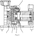
- FIG. 2 is a sectional view of one embodiment of the scroll compressor.
- FIG. 3 is a detailed view of Section A in FIG. 2 .
- FIG. 4 is a perspective view of one embodiment of the locating crankshaft.
- FIG. 5 is a perspective view of one embodiment of the locating crankshaft while the locking nut is an external hex nut.
- FIG. 6 is a perspective view of one embodiment of the locating crankshaft while operation holes are arranged on the locking nut.
- FIG. 7 is a perspective view of one embodiment of the locating crankshaft while operation dents are arranged on the locking nut.
- FIG. 8 is a perspective view of one embodiment of the locating crankshaft while a cross slot is arranged on the locating part.
- FIG. 9 is a perspective view of one embodiment of the locating crankshaft while a locating hole is arranged on the locating part.
- FIG. 10 is a perspective view of one embodiment of the locating crankshaft while the locating part is flat.
- FIG. 11 is a perspective view of one embodiment of the locating crankshaft while the cross section of the locating part is a hexagon.
- FIG. 12 is a perspective view of one embodiment of the locating crankshaft while an inner hex hole is arranged on the locating part.
- FIG. 13 is a perspective view of one embodiment of the scroll orbiting disk.
- FIG. 14 is a rear view of FIG. 13 .
- a scroll compressor comprises a fixed bearing seat ( 1 ), a scroll fixed disk ( 2 ), a scroll orbiting disk ( 3 ) and an orbiting disk bearing seat ( 4 ).
- the scroll fixed disk ( 2 ) is fixed to the fixed bearing seat ( 1 ), and the orbiting disk bearing seat ( 4 ) is located inside the fixed bearing seat ( 1 ).
- the scroll orbiting disk ( 3 ) is fixed to the orbiting disk bearing seat ( 4 ), and the scroll orbiting disk ( 3 ) matches the scroll fixed disk ( 2 ).
- first bearing bores ( 41 ) On the end face of the orbiting disk bearing seat ( 4 ), there are circumferentially three equally spaced first bearing bores ( 41 ), and on the end face of the fixed bearing seat ( 1 ), there are circumferentially three equally spaced second bearing bores ( 11 ).
- the second bearing bores ( 11 ) correspond with the first bearing bores ( 41 ) one-to-one.
- a locating crankshaft ( 5 ) is arranged between the corresponding first bearing bore ( 41 ) and second bearing bore ( 11 ).
- the front end of the locating crankshaft ( 5 ) is rotatably connected inside the first bearing bore ( 41 ) through the first bearing ( 42 ), and the rear end of the locating crankshaft ( 5 ) is rotatably connected inside the second bearing bore ( 11 ) through the second bearing ( 12 ).
- the rear end of the locating crankshaft ( 5 ) passes through the second bearing ( 12 ) and is inserted inside the through hole ( 13 ).
- the end on which the locating crankshaft ( 5 ) passes through the second bearing ( 12 ) is screw connected with a locking nut ( 9 ).
- a locking nut ( 9 ) is screw connected with the end on which the locating crankshaft ( 5 ) passes through the second bearing ( 12 ) .
- the locking nut ( 9 ) fits the external threads of the locating crankshaft ( 5 ).
- the locking nut ( 9 ) presses against the inner end face of the inner race of the second bearing ( 12 ).
- a locating structure is also arranged on the rear end of the locating crankshaft ( 5 ) to prevent the locating crankshaft ( 5 ) from rotating when the locking nut ( 9 ) is tightened.
- the locking nut ( 9 ) is an external hex nut.
- An external hex nut is a nut of a conventional structure, and the operation is convenient.
- the locking nut ( 9 ) may also be machined into a structure with the cross section of a polygon, and the locking nut ( 9 ) can be turned by clamping its outer walls.
- the locating structure comprises a locating part ( 59 ) on the end face of the locating crankshaft ( 5 ).
- a straight slot ( 56 ) is arranged on the end face of the locating part ( 59 ).
- the locating crankshaft ( 5 ) can be positioned through a screwdriver.
- the locating crankshaft ( 5 ) comprises a disk-shaped crank arm ( 51 ). Perpendicularly, there is a columnar first transmission part ( 52 ) on one side of the crank arm ( 51 ). There is an abutting boss ( 55 ) on the side of the crank arm ( 51 ), surrounding the first transmission part ( 52 ).
- the first locking plate ( 7 ) is fixed to the orbiting disk bearing seat ( 4 ), and the first locking plate ( 7 ) presses against the outer end face of the outer race of the first bearing ( 42 ), axially positioning the outer race of the first bearing ( 42 ).
- the abutting boss ( 55 ) presses against the outer end face of the inner race of the first bearing ( 42 ), axially positioning the inner race of the first bearing ( 42 ).
- the second locking plate ( 8 ) is fixed to the fixed bearing seat ( 1 ), and an adjusting gasket ( 6 ) is arranged between the second bearing ( 12 ) and the bottom face of the second bearing bore ( 11 ).
- the second locking plate ( 8 ) presses against the outer end face of the outer race of the second bearing ( 12 ). Under the action of the second locking plate ( 8 ), the inner end face of the outer race of the second bearing ( 12 ) presses against the adjusting gasket ( 6 ).
- the scroll orbiting disk ( 3 ) is fixed and installed onto the orbiting disk bearing seat ( 4 ) in advance.
- the first locking plate ( 7 ) and the second locking plate ( 8 ) are sleeved over both ends of the locating crankshaft ( 5 ).
- Two first bearings ( 42 ) are sleeved over one end of the locating crankshaft ( 5 ), and two second bearings ( 12 ) are sleeved over the other end of the locating crankshaft ( 5 ), and then two first bearings ( 42 ) are pressed into the first bearing bores ( 41 ) on the orbiting disk bearing seat ( 4 ).
- the first locking plate ( 7 ) is fixed to the orbiting disk bearing seat ( 4 ), making the first locking plate ( 7 ) presses the first bearing ( 42 ) firm.
- the orbiting disk bearing seat ( 4 ), the first bearings ( 42 ), the first locking plate ( 7 ), the locating crankshaft ( 5 ) and the second bearings ( 12 ) are installed in place, and the clearance errors among them are eliminated. Since all the components mentioned above are installed axially, the assembly process is relatively simple and the assembly precision is relatively high. Then the distance from the blades of the scroll orbiting disk ( 3 ) to the end face of the second bearing ( 12 ) is measured.
- an adjusting gasket ( 6 ) of an appropriate thickness will be selected.
- This adjusting gasket ( 6 ) is placed inside the second bearing bore ( 11 ).
- the locating crankshaft ( 5 ) will be maneuvered to allow the second bearings ( 12 ) on the locating crankshafts ( 5 ) to be aligned with and pressed into the second bearing bores ( 11 ).
- the second locking plate ( 8 ) is fixed to the fixed bearing seat ( 1 ). This makes the second locking plate ( 8 ) press the second bearing ( 12 ) firm, and the second bearing ( 12 ) press the adjusting gasket ( 6 ) firm, and achieves a higher fit precision between the scroll orbiting disk ( 3 ) and the scroll fixed disk ( 2 ) after the assembly process.
- the scroll orbiting disk ( 3 ) can rotate on the fixed bearing seat ( 1 ), and three locating crankshafts ( 5 ) can synchronically rotate as well. The ends of the locating crankshafts ( 5 ) can insert into the through holes ( 13 ). Locking nuts ( 9 ) are screwed onto the locating crankshafts ( 5 ).
- the locating crankshaft ( 5 ) is circumferentially located by matching a slot screwdriver with the straight slot ( 56 ) of the locating crankshaft ( 5 ), and then the external hex nut is clamped with and tightened by a wrench to allow the locking nuts ( 9 ) to press and locate onto the second bearings ( 12 ), achieving a precise positioning of the scroll orbiting disk ( 3 ).
- this can effectively prevent the locating crankshaft ( 5 ) from rotating, making the operation easier and more convenient, and hence simplifying the whole assembly process.
- the scroll is arranged on the front face of the scroll orbiting disk ( 3 ) in a spiral manner.
- These heat sinks ( 31 ) are arranged in the same direction, and an air duct ( 33 ) is formed in between two adjacent heat sinks ( 31 ). Both ends of the heat sink ( 31 ) extend to the outer rim of the scroll orbiting disk ( 3 ).
- the inlet part ( 326 ) and the outlet part ( 327 ) on one heat sink ( 31 ) are arranged symmetrically.
- An air inlet ( 331 ) connected to the air duct ( 33 ) is formed in between the inlet parts ( 326 ) of two adjacent heat sinks ( 31 ), and an air outlet ( 332 ) connected to the air duct ( 33 ) is formed in between the outlet parts ( 327 ) of two adjacent heat sinks ( 31 ).
- a fan is also arranged on the scroll compressor, and the air flow generated by the fan, as well as the natural wind, can blow the sides of the scroll orbiting disk ( 3 ).
- the air flow blows into one end of the air duct ( 33 ), and out of the other end.
- the air flow passing through the air duct ( 33 ) the heat on the scroll orbiting disk ( 3 ) and the heat sinks ( 31 ) can be taken away, and hence the temperature will be reduced. Also, reducing the temperature of the scroll orbiting disk ( 3 ) helps prevent the scroll orbiting disk ( 3 ) from deforming because of high temperature.
- the thickness of the heat sink ( 31 ) gradually increases from the top to the bottom.
- the connecting lines between the peak ( 322 ) of the heat sink ( 31 ) and its two adjacent troughs ( 323 ) are straight lines, and there is an angle between the lines connecting the peak ( 322 ) and its two adjacent troughs ( 323 ). This angle determines the bending degree of the wave-shaped heat sink ( 31 ). When this angle is too big, the stiffening effect is not significant. However, when the angle is too small, the resistive force against the air flow is also big. This is bad for the air flow to pass through. When the angle is 90°, the heat dissipation effect and stiffening effect of the scroll orbiting disk ( 3 ) is fairly good.
- the wave-shaped heat sink ( 31 ) has several peaks ( 322 ) and several troughs ( 323 ) in the lengthwise direction.
- the extending direction of the heat sinks ( 31 ) is the transversal direction
- the arranging direction of several heat sinks ( 31 ) is the longitudinal direction.
- longer heat sinks ( 31 ) can reinforce the strength of the scroll orbiting disk ( 3 ) in the transversal direction.
- the direction of the line connecting the peak ( 322 ) and the adjacent trough ( 323 ) is inclined relative to the transversal direction of the scroll orbiting disk ( 3 ), to stiffen the scroll orbiting disk ( 3 ) in the longitudinal direction.
- peaks ( 322 ) and troughs ( 323 ) in two adjacent heat sinks ( 31 ) are aligned.
- any heat sink ( 31 ) there is at least one peak ( 322 ) located in a triangular zone ( 36 ), which is enclosed by the corresponding peak ( 322 ) on the heat sink ( 31 ) above and the two troughs ( 323 ) on two sides of that peak ( 322 ) on that same heat sink ( 31 ). Therefore, in one transversal cross section, there are several heat sinks ( 31 ) to reinforce the strength of the scroll orbiting disk ( 3 ). The stiffening effect is significant, so as to prevent the scroll orbiting disk ( 3 ) from deforming. Therefore, the fit errors between the scroll orbiting disk ( 3 ) and the bearing and between the scroll orbiting disk ( 3 ) and the scroll fixed disk ( 2 ) will not be affected.
- the heat sink ( 31 ) has the first prop ( 324 ), which is columnar and perpendicular to the back of the scroll orbiting disk ( 3 ), in either the peak ( 322 ) or the trough ( 323 ) area.
- the outer diameter of the first prop ( 324 ) is greater than the thickness of the heat sink ( 31 ), and the outer diameter of the first prop ( 324 ) gradually increases from the top to the bottom.
- the top end of the first prop ( 324 ) is flush with the top edge of the heat sinks ( 31 ), stiffening the heat sinks ( 31 ) and the scroll orbiting disk ( 3 ).
- the second props ( 325 ) are located in the heat sinks ( 31 ). Similarly, the outer diameter of the second prop ( 325 ) also increases from the top to the bottom, and the outer diameter of the second prop ( 325 ) is greater than the outer diameter of the first prop ( 324 ). Lines connecting the three second props ( 325 ) form a triangle, and thus play the role of supporting frame for the scroll orbiting disk ( 3 ). In this embodiment, lines connecting the three second props ( 325 ) form an equilateral triangle, achieving a uniform stiffening effect of the scroll orbiting disk ( 3 ).
- This scroll compressor is basically the same as that of the first embodiment. The differences are:
- This scroll compressor is basically the same as that of the first embodiment. The differences are:
- the structure of the scroll compressor is basically the same as that of the first embodiment. The differences are:
- the locating structure comprises a locating part ( 59 ) on the end face of the locating crankshaft ( 5 ).
- a cross slot ( 57 ) is arranged on the end face of the locating part ( 59 ).
- the locating crankshaft ( 5 ) can be circumferentially positioned through a Phillips screwdriver.
- the structure of the scroll compressor is basically the same as that of the first embodiment. The differences are:
- the locating structure comprises a locating part ( 59 ) on the end face of the locating crankshaft ( 5 ).
- Several locating holes ( 58 ) are arranged on the end face of the locating part ( 59 ).
- the locating crankshaft ( 5 ) can be circumferentially positioned by matching screwdrivers or other tools with several locating holes ( 58 ).
- the structure of the scroll compressor is basically the same as that of the first embodiment. The differences are:
- the locating structure comprises a locating part ( 59 ) on the rear end face of the locating crankshaft ( 5 ).
- the locating part ( 59 ) is flat, and the outer end of the locating part ( 59 ) is outside the through hole ( 13 ).
- the locating part ( 59 ) is outside the through hole ( 13 ), making the locating part ( 59 ) to be easily clamped.
- the structure of the scroll compressor is basically the same as that of the first embodiment. The differences are:
- the locating structure comprises a locating part ( 59 ) on the rear end face of the locating crankshaft ( 5 ).
- the cross section of the locating part ( 59 ) is a polygon, and the outer end of the locating part ( 59 ) is outside the through hole ( 13 ).
- the locating part ( 59 ) is outside the through hole ( 13 ), and the cross section of the locating part ( 59 ) is a hexagon, making the locating part ( 59 ) to be easily clamped.
- the structure of the scroll compressor is basically the same as that of the first embodiment. The differences are:
- the locating structure comprises a locating part ( 59 ) on the end face of the locating crankshaft ( 5 ).
- An inner hex hole ( 591 ) is arranged on the end face of the locating part ( 59 ) allowing the locating part ( 59 ) to be circumferentially positioned by an Allen wrench or other tools.
Landscapes
- Engineering & Computer Science (AREA)
- General Engineering & Computer Science (AREA)
- Mechanical Engineering (AREA)
- Ocean & Marine Engineering (AREA)
- Applications Or Details Of Rotary Compressors (AREA)
- Rotary Pumps (AREA)
Abstract
Description
-
- 1 Fixed Bearing Seat
- 11 Second Bearing Bore
- 12 Second Bearing
- 13 Through Hole
- 14 Scroll Fixed Disk
- 15 Scroll Orbiting Disk
- 31 Heat Sink
- 322 Peak
- 323 Trough
- 324 First Prop
- 325 Second Prop
- 326 Inlet Part
- 327 Outlet Part
- 33 Air Duct
- 331 Air Inlet
- 332 Air Outlet
- 36 Zone
- 4 Orbiting Disk Bearing Seat
- 41 First Bearing Bore
- 42 First Bearing
- 5 Locating Crankshaft
- 51 Crank Arm
- 52 First Transmission Part
- 53 Second Transmission Part
- 54 Abutting Edge
- 55 Abutting Boss
- 56 Straight Slot
- 57 Cross Slot
- 58 Locating Hole
- 59 Locating Part
- 591 Inner Hex Hole
- 6 Adjusting gasket
- 7 First Locking Plate
- 8 Second Locking Plate
- 9 Locking Nut
- 91 Operation Hole
- 92 Operation Dent
Claims (10)
Applications Claiming Priority (9)
| Application Number | Priority Date | Filing Date | Title |
|---|---|---|---|
| CNCN201620356055.0 | 2016-04-25 | ||
| CNCN201610265940.2 | 2016-04-25 | ||
| CN201620356055 | 2016-04-25 | ||
| CN201620356055U | 2016-04-25 | ||
| CN201610265940.2A CN105756935A (en) | 2016-04-25 | 2016-04-25 | Oilless vortex air compressor |
| CN201610265940 | 2016-04-25 | ||
| CNCN201610796081.X | 2016-08-31 | ||
| CN201610796081.XA CN106122011B (en) | 2016-04-25 | 2016-08-31 | A kind of screw compressor |
| CN201610796081 | 2016-08-31 |
Publications (2)
| Publication Number | Publication Date |
|---|---|
| US20170306962A1 US20170306962A1 (en) | 2017-10-26 |
| US10544785B2 true US10544785B2 (en) | 2020-01-28 |
Family
ID=57271091
Family Applications (1)
| Application Number | Title | Priority Date | Filing Date |
|---|---|---|---|
| US15/496,001 Active 2038-03-01 US10544785B2 (en) | 2016-04-25 | 2017-04-25 | Scroll compressor with a locating crankshaft |
Country Status (2)
| Country | Link |
|---|---|
| US (1) | US10544785B2 (en) |
| CN (2) | CN106122011B (en) |
Families Citing this family (5)
| Publication number | Priority date | Publication date | Assignee | Title |
|---|---|---|---|---|
| CN108087036B (en) * | 2018-01-19 | 2024-04-26 | 邢台癸酉新能源科技有限公司 | Magnetic suspension vortex engine |
| KR102630534B1 (en) * | 2022-01-14 | 2024-01-29 | 엘지전자 주식회사 | Scroll compressor |
| CN117646723B (en) * | 2024-01-29 | 2024-04-26 | 蜂巢蔚领动力科技(江苏)有限公司 | Anti-rotation structure of scroll compressor and scroll compressor |
| CN118208416B (en) * | 2024-05-22 | 2024-08-20 | 德耐尔节能科技(上海)股份有限公司 | End face gap adjustable screw air compressor |
| CN120042785B (en) * | 2025-04-25 | 2025-07-29 | 江苏诺躬新能源汽车空调有限公司 | Highly wear-resistant vortex air conditioner compressor assembly |
Citations (8)
| Publication number | Priority date | Publication date | Assignee | Title |
|---|---|---|---|---|
| US2090782A (en) * | 1934-08-27 | 1937-08-24 | Carraway Engineering Company I | Air conditioning system |
| US20030223898A1 (en) * | 2001-12-28 | 2003-12-04 | Anest Iwata Corporation | Scroll fluid machine and assembling method thereof |
| US20040042920A1 (en) * | 2001-09-19 | 2004-03-04 | Anest Iwata Corporation | Scroll-type fluid machine |
| US20050220649A1 (en) * | 2004-03-30 | 2005-10-06 | Anest Iwata Corporation | Scroll fluid machine |
| US20130149179A1 (en) * | 2010-09-30 | 2013-06-13 | Anest Iwata Corporation | Scroll fluid machine |
| US20140119970A1 (en) * | 2012-10-31 | 2014-05-01 | Hitachi Industrial Equipment Systmes Co., Ltd. | Scroll Fluid Machine |
| CN104847660A (en) | 2015-05-28 | 2015-08-19 | 郭辰 | Low-compression-ratio and fully-oilless scroll air compressor assembly |
| CN105041646A (en) | 2015-09-02 | 2015-11-11 | 广州广涡压缩机有限公司 | Oil-free scroll air compressor |
Family Cites Families (6)
| Publication number | Priority date | Publication date | Assignee | Title |
|---|---|---|---|---|
| JP3134656B2 (en) * | 1994-03-18 | 2001-02-13 | 株式会社日立製作所 | Scroll compressor and assembly method thereof |
| JP3980718B2 (en) * | 1997-09-26 | 2007-09-26 | 株式会社日立製作所 | Scroll type fluid machine and adjusting method of thrust gap |
| JP4718831B2 (en) * | 2004-12-27 | 2011-07-06 | アネスト岩田株式会社 | Scroll fluid machinery |
| CN104405618B (en) * | 2014-10-23 | 2016-06-22 | 浙江西田机械有限公司 | A kind of bearing of compressor mechanism for axial adjusting |
| CN104895793A (en) * | 2015-06-09 | 2015-09-09 | 苏州艾可普斯机电科技有限公司 | Integrated oilless vortex gas compressor |
| CN206190527U (en) * | 2016-04-25 | 2017-05-24 | 徐道敏 | Scroll compressor's error adjustment structure |
-
2016
- 2016-08-31 CN CN201610796081.XA patent/CN106122011B/en active Active
- 2016-08-31 CN CN201621027722.7U patent/CN206647263U/en not_active Withdrawn - After Issue
-
2017
- 2017-04-25 US US15/496,001 patent/US10544785B2/en active Active
Patent Citations (8)
| Publication number | Priority date | Publication date | Assignee | Title |
|---|---|---|---|---|
| US2090782A (en) * | 1934-08-27 | 1937-08-24 | Carraway Engineering Company I | Air conditioning system |
| US20040042920A1 (en) * | 2001-09-19 | 2004-03-04 | Anest Iwata Corporation | Scroll-type fluid machine |
| US20030223898A1 (en) * | 2001-12-28 | 2003-12-04 | Anest Iwata Corporation | Scroll fluid machine and assembling method thereof |
| US20050220649A1 (en) * | 2004-03-30 | 2005-10-06 | Anest Iwata Corporation | Scroll fluid machine |
| US20130149179A1 (en) * | 2010-09-30 | 2013-06-13 | Anest Iwata Corporation | Scroll fluid machine |
| US20140119970A1 (en) * | 2012-10-31 | 2014-05-01 | Hitachi Industrial Equipment Systmes Co., Ltd. | Scroll Fluid Machine |
| CN104847660A (en) | 2015-05-28 | 2015-08-19 | 郭辰 | Low-compression-ratio and fully-oilless scroll air compressor assembly |
| CN105041646A (en) | 2015-09-02 | 2015-11-11 | 广州广涡压缩机有限公司 | Oil-free scroll air compressor |
Also Published As
| Publication number | Publication date |
|---|---|
| CN106122011B (en) | 2018-09-14 |
| CN206647263U (en) | 2017-11-17 |
| CN106122011A (en) | 2016-11-16 |
| US20170306962A1 (en) | 2017-10-26 |
Similar Documents
| Publication | Publication Date | Title |
|---|---|---|
| US10544785B2 (en) | Scroll compressor with a locating crankshaft | |
| US7357627B2 (en) | Scroll fluid machine | |
| EP4123189A1 (en) | Anti-disassembly joint and anti-disassembly joint assembly | |
| US20190219089A1 (en) | Hybrid three-point drive fastener | |
| CN106050861A (en) | Anti-releasing thread structure and its forming tool | |
| CN108425940A (en) | A kind of big carrying elastic foil gas bearing with automatic adjusument | |
| CN204524887U (en) | A kind of self-interacting type pressure plate structure | |
| CN205415496U (en) | Gear shaft bearing detaching device | |
| EP3239531B1 (en) | A scroll disk heat dissipation assembly of scroll compressors | |
| US6368053B1 (en) | Impeller clearance adjustment system | |
| KR101731640B1 (en) | Turbo compressor | |
| CN114423945A (en) | Single-shaft eccentric screw pump | |
| GB2440660A (en) | Screw compressor with coaxial bearing bores in unitary housing | |
| US11370092B2 (en) | Torque connector structure | |
| CN102773526B (en) | Tool assembly capable of adjusting cutting rotation radius | |
| CN202381338U (en) | Assembly structure of balance weight and rotating shaft and rotary machine | |
| US12055143B2 (en) | Screw compressor with adjustable passage | |
| CN213616498U (en) | Tool for adjusting centrifugal compressor impeller clearance | |
| CN212429988U (en) | Sheet metal component that can install fast | |
| CN223729567U (en) | Compressor rotor balancing weight, compressor rotor assembly and compressor assembly | |
| CN108188479A (en) | A kind of fixture of auxiliary clamp knife saw | |
| CN222200374U (en) | Detachable wrench chuck unit | |
| CN219465002U (en) | Portable anchor clamps extension connecting rod | |
| CN219724627U (en) | Expansion shaft | |
| CN117477879A (en) | Motor stator centering and fixing structure, motor and compressor applying same |
Legal Events
| Date | Code | Title | Description |
|---|---|---|---|
| AS | Assignment |
Owner name: ZHEJIANG JIENENG COMPRESSION EQUIPMENT CO., LTD., CHINA Free format text: ASSIGNMENT OF ASSIGNORS INTEREST;ASSIGNORS:XU, DAOMIN;WANG, MIN;REEL/FRAME:042132/0992 Effective date: 20170425 Owner name: ZHEJIANG JIENENG COMPRESSION EQUIPMENT CO., LTD., Free format text: ASSIGNMENT OF ASSIGNORS INTEREST;ASSIGNORS:XU, DAOMIN;WANG, MIN;REEL/FRAME:042132/0992 Effective date: 20170425 |
|
| STPP | Information on status: patent application and granting procedure in general |
Free format text: DOCKETED NEW CASE - READY FOR EXAMINATION |
|
| STPP | Information on status: patent application and granting procedure in general |
Free format text: NON FINAL ACTION MAILED |
|
| STPP | Information on status: patent application and granting procedure in general |
Free format text: RESPONSE TO NON-FINAL OFFICE ACTION ENTERED AND FORWARDED TO EXAMINER |
|
| STPP | Information on status: patent application and granting procedure in general |
Free format text: PUBLICATIONS -- ISSUE FEE PAYMENT RECEIVED |
|
| STCF | Information on status: patent grant |
Free format text: PATENTED CASE |