US1054314A - Motor-truck. - Google Patents
Motor-truck. Download PDFInfo
- Publication number
- US1054314A US1054314A US31162706A US1906311627A US1054314A US 1054314 A US1054314 A US 1054314A US 31162706 A US31162706 A US 31162706A US 1906311627 A US1906311627 A US 1906311627A US 1054314 A US1054314 A US 1054314A
- Authority
- US
- United States
- Prior art keywords
- motor
- axles
- shaft
- truck
- gear
- Prior art date
- Legal status (The legal status is an assumption and is not a legal conclusion. Google has not performed a legal analysis and makes no representation as to the accuracy of the status listed.)
- Expired - Lifetime
Links
Images


Classifications
-
- B—PERFORMING OPERATIONS; TRANSPORTING
- B61—RAILWAYS
- B61C—LOCOMOTIVES; MOTOR RAILCARS
- B61C9/00—Locomotives or motor railcars characterised by the type of transmission system used; Transmission systems specially adapted for locomotives or motor railcars
- B61C9/02—Transmission systems in or for locomotives or motor railcars with reciprocating piston steam engines
- B61C9/06—Transmission systems in or for locomotives or motor railcars with reciprocating piston steam engines having toothed, chain, friction, or belt gearing
Definitions
- This invention relate to an improvement in motor trio-ks t'lll
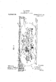
- Figure 1 is a side elevation oi a motor truck; embodying my inr provements.
- Fig. 2 is' a view partly in plan and partly in horizontal section of the Fig. 3 isa section on the line 3--3,
- 1 indicates as an em t'irety the main frame.
- This preferably eonsislS of longitudinal side beams 2, 2, and end pieces 3, 3', rigidly secured to the side beams.
- these longitudinal and transverse members of the main frame should be made of wood, although they may be made of steel, or wood reinforced by steel.
- it de- 4 indicates a platform whieh is ar ranged upon the said frame. it may eonsist. of any suitable material and may be secured in position in any desired manner.
- journal boxes 0 for the front and rear axles are plates depending, from the longitudinal members 2 2 arran 'ed near either v 8 h H it rests upon the horizontal wall and bears end. thereof and adapted to hold in position the journal boxes 0 for the front and rear axles.
- These journal boxes may be of any well known kind, but i find most suitable the type in which wearing pieees boa r upon the ⁇ Nile and have interl'msed between them and an adjacent portion of the frame a spring or springs which allow the requisite Specification oi Letters Patent.
- the main frame at either side is prefer ably trussed by means of the truss rods or bars 7, T, eat-h having the horizontal members T to which the journal boxes earried by the plates 5 are secured, the journal boxes and their carrying plates 5 serving as the tie bars or struts between the truss rods and beams 2, 2.
- This construction insures a rigid bracing ot' the frame and at the same time a simple and etlioient arrangement ol the journal boxes.
- the motor At its front end the motor is secured to an angle plate or braeket 17 which in turn is seenred to the cross bltlte to which. as unheated, is preferably an angle plate with its walls arranged horizontally and vertirallv so that the said bracket crank shaft at 'points between the crank case and the longitudinal bar l3.
- 35 is a bevel gear of the same pitch diameter as the bevel wheel 34. It. also is loosely mounted upon saidsleeve 33 but is arranged to mesh with said bevel pinion 21 on the opposite side thereof from the bevel gear 34.
- 34' is a clutch jaw or element rigidly secured to the bevel gear 34-, and 35' is a clutch elementv rigidly secured to the gear wheel 35.
- This movable clutch element 36 is a double acting movable clutch element splined to the sleeve 33'and carrying the forward extending jaw 36 which is adapted to engage with the jaw 34 on the bevel gear 34, and the rearwardly extending jaw 36 which is adapted to engage with the jaw 35' on the bevel ear 35.
- This movable clutch element 36 preferably has a collar with a grooved periphery, with the side walls of which groove, at diametrically opposite points, the arms of a yoke 37 engage.
- This yoke 37 is carried by a swinging arm '38 which is pivotally connected at 38' intermediate-of its ends to the gear frame 19, At itsouter end this lever 38 is pivotally connected to a yoke arm 39.
- 40 are links flexibly connectingthe said yoked arm to a swinging lever 41 pivoted at 42 to the beam 13.
- 43 is a hand lever extending from a pointabovc the platform on the car, and within easy reach of the operator, downward through the said platform, this lever being pivotally mounted at 43 an any suita-ble manner.
- 44 is a link connecting'the lower -for'us in this mechanism at this point.
- illustration 1 the purpose of illustration 1 have indicatedthe planetary drum 46 lcosey mounted upon t 33 and carrying at its front surfacethe pin- By shifting the said hand gear system as comEfl'sing a e sleeve ions 47.
- These pinions mesh with an internal gear 48 carried by a shell 49 which is rigidly secured to the driveshziRrQQ. 50 is a gear rigidly secured to the sleeve 33 within the shell 49 and adapted to mesh with the pinions 47 carriedby the'drum 4.6.
- sleeve 33 is a brake band fitted about the drum 46 and adapted to be clamped thereto to hold the drum stationary and to cause the operation of the planetary gears to transmit metion from the sleeve 33 to the drive she.
- etary gear 45 It is arranged with its handle above the. platform of the car within easy reach of the o erator; it is pivoted at 53" and extends ownward through the .95 oted at 53 to the adjacent longitudinal beam 54 is a hand lever for operating the planplatform and has-its lower end connected to the bell crank lever 52 by means of a link 54.
- I have found it desirable to employ the same lever both for controlling the operation of the planetary gear and the application of brakes forstopping the travel ofzthe" 58 is a transversely arranged shaft] cured eteither'end to the beams 2, 2', of'the' main frame.
- 59,59 are lever arms rigidly secured to the said transverse shaft 58 near either end thereof and each connected to the swingable brake shoe-carrying beam 56.103
- the motor shown is supposed to be an air-cooled one and rouse quently no water tank is necessary.
- the tanlpo il for hydrocarbon and the mulller lit may be supporttal from the sumilemeulal frame 12 in any suitable manner.
- n'ieehanisnn The operationof the n'ieehanisnn is as follows: Assuming that the motor is in opera tion and the fiy wheel is rotating in the tlireclion indicated by th: arrow in Fig. ll, it will be noted that when the double acting clutch element 36 is in the neutral position shown in Fig. 2', that the engine will run idle and that the sleeve 33 will remain idle it it is desired to drive the gagl: torward, the hand lever 43 is shifted in such manner as to cause the clutch jaw 36 on the double acting clutch element 56 to engage with the clutch element 34- carried by the bevel gear 34.. This will cause the rotation of the sleeve 33 in ant-i-cloclm'ise direction looking at it from the right in Fig. 1!. The oleevc will drive the gear in anti-clockwise direction.
- the movable clutch element 36 In order to cause the reverse or rear and travel of the truck, the movable clutch element 36 should be shifted by, the hand lever lil so as to cause the engagement of its jaw 36" Willi the jaw 35 upon the bevel gear 235.
- the motor and transmission is so arranged that power is applied for driving both the front and rear axles in either direction and through a planetary system of gearing which permits; the locomotive to he started in either direction without sudden jerks or strains and which will at'i'ord compensation in the transmissioi'i where undue strains are eneounlerml when the locomotive is running.
- a motor trurlc the combination of a main frame, truss work for the longitudinal members of the main l'rame, having vertiral struts or tie pieces carrying bearing boxes.
- axles mounted in said bearing boxes tract: wheels rigidly secured to said axles, a siu'iplemental frame comprising three parallel longitudinal beams each loosely mounted at either end upon the adjacent axle, cross pieces connecting said parallel beams together, a motor supported by and hctwurn the middle one of said longitudinal members and one of the outside ones, and power lransmittiiug; mechanism interposed etween aaiil motor and said axles and supported by and between said middle l0ngitudinal member. and the other outside one.
- a. motor truck the combination of a pair of axles, wheels secured lilltl'ljlfl, a longitudinally arranged drive eha'tt, gearing etween the opposite ends of the said shaft and the said axles, arranged to turn both axles and wheels simultaneously in the some direction, a motor mounted upon the truck with its shaft p sitioned transversely, gearing interposed between the motor and the said drive shaft, and means for operativelv connecting the motor with the drive sha t arranged to be adjusted to cause rotation of the latter in one direction or the other at will a:lhstautially as set forth.
- a motor truck the combination of a pair of axles, trael: wheels rigidly secured thereto, a framework loosely mounted on said axles and. connecting them together, a reciprocating motor secured on said frame work and having its crank shaft arranged parallel with said axles, a main drive shaft arranged at right angles to said crank shaft, gearing interposed between either end of said main drive shaft and the adjacent axle, planetary gearing arranged on said main drive shaft, and power transmitting mechanism interposed between said crank shaft and aaitl planetary gearing and adapted to be adjusted to actuate said planetary gearlug so as to cause it to rotate the said mam llrivc shaft in either direction.
- a lu-vel gear secured to the outer end of said crank shall, a pair ol hovel gears loosely mounted upon said sleeve and each adapted to mesh with said bevel gear on the crank shaft at one side thereof, double acting means for connecting either of said bevel gears to the sleeve, and planetary gearing interposed between said sleeve and said drive shaft.
- a motor truck the combination of a pair of axles, wheels secured thereto, a longitudinally arranged drive shaft, gearing be-' tween the opposite ends of the said shaft and the said axles arranged to turn both axles and wheels simultaneously in the same direction, a motor mounted upon the truck with its shaft extending transversely, a bevel gear on the motor shaft, two bevel gears rotatably mounted on the drive shaft and meshing, with the gear on the motor shaft at opposite sides thereof, and means for operatively connecting with the drive shaft either of the bevel gears mounted thereon.
- a motor truck the combination of a pair of axles, track wheels rigidly secured thereto, a framework mounted on the axles and connecting them together, a motor secured on the frame work with its shaft arranged parallel with the axles, a main drive sha t arranged at right angles with the motor shafit and with the axles, caring between the drive shaft and each ax e for causing the simultaneous rotation of the axles in the same direction, an element rotatable independently of the motor shaft and of the drive shaft, gearing between the motor shaft and the said element adapted to be adjusted to cause the rotation of the said element in either direction, and change speed gearing between the said element and the drive shaft.
- a motor truck the combination of a pair of axles, track wheels rigidly secured 40 thereto, a frame-work mounted on the axles and connecting them, together, a motor mounted on the frame-work with its shaft arranged transversely, a longitudinally arranged drive shaft, gearing between the either direction, and planetary gearing interposed between the sleeve and the drive shaft.
- the said power transmitting mechanism comprising planetary gearing, a brake, a hand lever, and connections between the handlever and the planetary gearing and between the hand lever and the brake, whereby the gearing may be made operative and the brake simultaneously released or the brake may be applied and the gearing simultaneously made nope'rative.
Landscapes
- Engineering & Computer Science (AREA)
- Transportation (AREA)
- Mechanical Engineering (AREA)
- Retarders (AREA)
Description
H. S. RIDDLE.
MOTOR TRUCK.
APPLIOATION FILED APR. 14, 1906.
Patented Feb. 25, 1913.
3 SHEETS-SHEET 1.
INVENTOR IAYRZ Z BY HIS HTTORNLw H. s. RIDDLE.
MOTOR TRUCK.
Patented Feb. 25, 1913.
INVENTOR BY HIS ATTORNEY;
APPLICATION FILED APR. H. 1906 H. S. RIDDLE.
MOTOR TRUCK.
APPLICATION FILED APR. 14, 1006:
1,054,314: Patented Feb. 25, 1913.
3 BHBETSSHBET 3.
sired.
ItiiGNAltt'D S. RIDDLE, O1" COLUMBUS. OHIO. ASSIG'NOR, BY MESNF ASSIGNMEN'IS. T THE JEFFREY MANUFACTURING COMPANY. A CORPORATKON OF OHIO.
MOTOR TRUCK.
Application tiled April 14,
tie it ltnown that l. llo\\'.\nn r ltionmc. a ritixlen olthe tnited Stalwart-siding at Columbus. in the ronniy oi Franklin and State of Ohio. have invented ertain new and useful improvements in .\lotor-'lrurl s. ot' whieh the following is a speriliration, releremre being bad therein to th aeeonipany inn drawing.
This invention relate to an improvement in motor trio-ks t'lll|)l \'lll I hydroearlmn niotors tor piover-generating purposes.
it pertains particularly to yard trucks ot the type g nerally used for hauling either inatm'ial or both material and ears in and about manutorturing plants, and for similar purposes.
My object has been to devise a simple, in-
expensive truck having its parts all readily accessible and having a )latform relatively low down and substantially unobstruoted by any of the mechanical parts.
In the drawings --Figure 1 is a side elevation oi a motor truck; embodying my inr provements. Fig. 2 is' a view partly in plan and partly in horizontal section of the Fig. 3 isa section on the line 3--3,
In the drawings, 1 indicates as an em t'irety the main frame. This preferably eonsislS of longitudinal side beams 2, 2, and end pieces 3, 3', rigidly secured to the side beams. For the purpose of lightness, oheapness, and resilience of. frame structure, I. prefer that. these longitudinal and transverse members of the main frame should be made of wood, although they may be made of steel, or wood reinforced by steel. it de- 4 indicates a platform whieh is ar ranged upon the said frame. it may eonsist. of any suitable material and may be secured in position in any desired manner.
5 are plates depending, from the longitudinal members 2 2 arran 'ed near either v 8 h H it rests upon the horizontal wall and bears end. thereof and adapted to hold in position the journal boxes 0 for the front and rear axles. These journal boxes may be of any well known kind, but i find most suitable the type in which wearing pieees boa r upon the {Nile and have interl'msed between them and an adjacent portion of the frame a spring or springs which allow the requisite Specification oi Letters Patent.
'ta't ented Feb. 25, 1913.
1906. Serial No. 311.627.
rertieal play of the frame relative to the axles.
The main frame at either side is prefer ably trussed by means of the truss rods or bars 7, T, eat-h having the horizontal members T to which the journal boxes earried by the plates 5 are secured, the journal boxes and their carrying plates 5 serving as the tie bars or struts between the truss rods and beams 2, 2. This construction insures a rigid bracing ot' the frame and at the same time a simple and etlioient arrangement ol the journal boxes.
t), 10, indicate front and rear axles res eetively, and 11 the track wheels thereon. i s the truck is adapted for use upon a trael; and is relatively short coupled, it is not llt't" essary to make either of the axles steering axles.
The motor amt the transmission interposed between it and the axles'are preterably supported on a supplemental rigid frame 12 arranged beneath the main frame of the truck and eomprisim, longitudinally parallel bars or rods 13, 13, 1.3, secured at either end in a suitable manner to the ad jaeent axles. in foot the axles may be eonsidered as a part of the sup 'ilemental frame. At suitable intervals transverse bars or brat-es i4. 15, extend lit-tween the longitudinal beams 1.3, 13, and are secured to them so as to fornr a framework on whieh the motor 16 is mounted. This motor 16 is preferably a hydrorarbon motor and may be of any suitable or well known type. its cylinder to rests upon the t'l'oss brace H which is preferably eurved as indirated to accommodate it. to the shape of the side walls of the Cylinder. At its front end the motor is secured to an angle plate or braeket 17 which in turn is seenred to the cross bltlte to which. as unheated, is preferably an angle plate with its walls arranged horizontally and vertirallv so that the said bracket crank shaft at 'points between the crank case and the longitudinal bar l3.
l9 as a gear frame extending between the in which it. is mounted. 2L is a bevel gear rigidly secured tothe said crank shaft inside the said gear frame. 22 is longitudinally arranged drive shaft eftending through bearings 23, 24, in the said gear frame 19. Near its front end this driveishaft 22 is mounted in a bearing 25 carried by a bracket 26 suitably secured to the supplemental frame 12. 27 is a bevel inion rigidly secured to the front end 0% said drive shaft and 28 is a bevel gear rigidly secured to the front axle 9 and arranged to mesh with s id bevel pinion. Near its rear end this di ive shaft 22 is mounted in a bearing 9 carried by a bracket 30 which is also 51 itably s'e- 'cured to the supplemental frame 12. 31 is a bevel pinion rigidly securedto the rear end of said drive shaft and arranged to mesh with a bevel gear 32 rigidly secured to the rear axle 10. a I
33 is a sleeve loose y mounted upon the drive shaft 22 and v'i'thin the bear'ings23 and 24, it extending forward beyond said front bearing 23 for some distance; This sleeve is free to turn within the bearin s and also relatively to the said drive sha t.
34 is a'bevel gear loosely mounted upon said sleeve and arranged to mesh with the bevel pinion 21 on the crank shaft. 35 is a bevel gear of the same pitch diameter as the bevel wheel 34. It. also is loosely mounted upon saidsleeve 33 but is arranged to mesh with said bevel pinion 21 on the opposite side thereof from the bevel gear 34.
34' is a clutch jaw or element rigidly secured to the bevel gear 34-, and 35' is a clutch elementv rigidly secured to the gear wheel 35.
36 isa double acting movable clutch element splined to the sleeve 33'and carrying the forward extending jaw 36 which is adapted to engage with the jaw 34 on the bevel gear 34, and the rearwardly extending jaw 36 which is adapted to engage with the jaw 35' on the bevel ear 35. This movable clutch element 36 preferably has a collar with a grooved periphery, with the side walls of which groove, at diametrically opposite points, the arms of a yoke 37 engage. This yoke 37 is carried by a swinging arm '38 which is pivotally connected at 38' intermediate-of its ends to the gear frame 19, At itsouter end this lever 38 is pivotally connected to a yoke arm 39. 40 are links flexibly connectingthe said yoked arm to a swinging lever 41 pivoted at 42 to the beam 13.
43 is a hand lever extending from a pointabovc the platform on the car, and within easy reach of the operator, downward through the said platform, this lever being pivotally mounted at 43 an any suita-ble manner. 44 is a link connecting'the lower -for'us in this mechanism at this point. For
the purpose of illustration 1 have indicatedthe planetary drum 46 lcosey mounted upon t 33 and carrying at its front surfacethe pin- By shifting the said hand gear system as comEfl'sing a e sleeve ions 47. These pinions mesh with an internal gear 48 carried by a shell 49 which is rigidly secured to the driveshziRrQQ. 50 is a gear rigidly secured to the sleeve 33 within the shell 49 and adapted to mesh with the pinions 47 carriedby the'drum 4.6.
51 is a brake band fitted about the drum 46 and adapted to be clamped thereto to hold the drum stationary and to cause the operation of the planetary gears to transmit metion from the sleeve 33 to the drive she.
22 in the well known manner. This brake:-
band is operated by a bell crank lever 52 pivof the'supplemental frame.
etary gear 45. It is arranged with its handle above the. platform of the car within easy reach of the o erator; it is pivoted at 53" and extends ownward through the .95 oted at 53 to the adjacent longitudinal beam 54 is a hand lever for operating the planplatform and has-its lower end connected to the bell crank lever 52 by means of a link 54. I have found it desirable to employ the same lever both for controlling the operation of the planetary gear and the application of brakes forstopping the travel ofzthe" 58 is a transversely arranged shaft] cured eteither'end to the beams 2, 2', of'the' main frame. 59,59, are lever arms rigidly secured to the said transverse shaft 58 near either end thereof and each connected to the swingable brake shoe-carrying beam 56.103
means of links 69'. '61 is an arm rigidly secured to the said shaft 58 at the 'siame side of.
the machine as the gear-controlling lever 54 v to which it is connected by excellent a link or;bar 62. It will be noted thatthe arrangemeat of the levers and connections between ing wheels, while when the said hand lever is thrown in the opposite direction to render inactive the planetary grarin the brake shoes are caused to approach the periphery of their respective track wheels and it the lever is forced far enough hi this dirertion the brake'shoes will he applied to stop the rotation of the front driving wheels.
in the drawings, the motor shown is supposed to be an air-cooled one and rouse quently no water tank is necessary. The tanlpo il for hydrocarbon and the mulller lit may be supporttal from the sumilemeulal frame 12 in any suitable manner.
The operationof the n'ieehanisnn is as follows: Assuming that the motor is in opera tion and the fiy wheel is rotating in the tlireclion indicated by th: arrow in Fig. ll, it will be noted that when the double acting clutch element 36 is in the neutral position shown in Fig. 2', that the engine will run idle and that the sleeve 33 will remain idle it it is desired to drive the trucl: torward, the hand lever 43 is shifted in such manner as to cause the clutch jaw 36 on the double acting clutch element 56 to engage with the clutch element 34- carried by the bevel gear 34.. This will cause the rotation of the sleeve 33 in ant-i-cloclm'ise direction looking at it from the right in Fig. 1!. The oleevc will drive the gear in anti-clockwise direction.
' Wow, it the operator shifts the hand lever :i-l:
so as to apply the brake band 51 to the drum ll; of the planetary gear, thus holding the pinions 47 from bodily rotation about the axis of the drive shaft 22, then the gear 5!) will drive the said pinions -17 in clockwise direction and they will. drive the internal gear 48 in clockwish tlirect'idn so as to rotate the main drive shaft 135! in the same direetion and the bevel pinions 97 and 31 on the said drive shaft will rotate the bevel gears and 32 on the front and rear axles respectively in such manner as to cause the forward.travcl oi the truck.
In order to cause the reverse or rear and travel of the truck, the movable clutch element 36 should be shifted by, the hand lever lil so as to cause the engagement of its jaw 36" Willi the jaw 35 upon the bevel gear 235.
This will cause the rotation of the sleeve 33 in an opposite direction from whirh it is rotated by the gear wheel 3-1,,when thelattcr is in operation, and consequently when the planetary gear is rendered active it will rotate the main drive shaft 22 in a dircttio'i'! opposite to that first described and consequently the truck will move rearward.
It will be noted that the motor and transmission is so arranged that power is applied for driving both the front and rear axles in either direction and through a planetary system of gearing which permits; the locomotive to he started in either direction without sudden jerks or strains and which will at'i'ord compensation in the transmissioi'i where undue strains are eneounlerml when the locomotive is running.
l claim-- l. In a motor trurlc, the combination of a main frame, truss work for the longitudinal members of the main l'rame, having vertiral struts or tie pieces carrying bearing boxes. axles mounted in said bearing boxes, tract: wheels rigidly secured to said axles, a siu'iplemental frame comprising three parallel longitudinal beams each loosely mounted at either end upon the adjacent axle, cross pieces connecting said parallel beams together, a motor supported by and hctwurn the middle one of said longitudinal members and one of the outside ones, and power lransmittiiug; mechanism interposed etween aaiil motor and said axles and supported by and between said middle l0ngitudinal member. and the other outside one.
.2. In a. motor truck, the combination of a pair of axles, wheels secured lilltl'ljlfl, a longitudinally arranged drive eha'tt, gearing etween the opposite ends of the said shaft and the said axles, arranged to turn both axles and wheels simultaneously in the some direction, a motor mounted upon the truck with its shaft p sitioned transversely, gearing interposed between the motor and the said drive shaft, and means for operativelv connecting the motor with the drive sha t arranged to be adjusted to cause rotation of the latter in one direction or the other at will a:lhstautially as set forth.
'In a motor truck, the combination of a pair of axles, trael: wheels rigidly secured thereto, a framework loosely mounted on said axles and. connecting them together, a reciprocating motor secured on said frame work and having its crank shaft arranged parallel with said axles, a main drive shaft arranged at right angles to said crank shaft, gearing interposed between either end of said main drive shaft and the adjacent axle, planetary gearing arranged on said main drive shaft, and power transmitting mechanism interposed between said crank shaft and aaitl planetary gearing and adapted to be adjusted to actuate said planetary gearlug so as to cause it to rotate the said mam llrivc shaft in either direction.
4. in a motor truok, the combination of a pair of axles, trarlc wheels rigidly Secured thercto,a -frameworklooselymounted on said axles and connecting them, together, a reciprocating motor srriu'ed on said frame work and having its rranlt shaft arranged parallel with said axles, a main drive shaft arranged at right angles to said crank shaft gum-inn interposed between either end .ot said main drive shaft and the adjacent axle, a ol wve loosely mounted on said drive. shaft, a lu-vel gear secured to the outer end of said crank shall, a pair ol hovel gears loosely mounted upon said sleeve and each adapted to mesh with said bevel gear on the crank shaft at one side thereof, double acting means for connecting either of said bevel gears to the sleeve, and planetary gearing interposed between said sleeve and said drive shaft. v
5. In a motor truck, the combination of a pair of axles, wheels secured thereto, a longitudinally arranged drive shaft, gearing be-' tween the opposite ends of the said shaft and the said axles arranged to turn both axles and wheels simultaneously in the same direction, a motor mounted upon the truck with its shaft extending transversely, a bevel gear on the motor shaft, two bevel gears rotatably mounted on the drive shaft and meshing, with the gear on the motor shaft at opposite sides thereof, and means for operatively connecting with the drive shaft either of the bevel gears mounted thereon.
6. In a motor truck, the combination of a pair of axles, track wheels rigidly secured thereto, a framework mounted on the axles and connecting them together, a motor secured on the frame work with its shaft arranged parallel with the axles, a main drive sha t arranged at right angles with the motor shafit and with the axles, caring between the drive shaft and each ax e for causing the simultaneous rotation of the axles in the same direction, an element rotatable independently of the motor shaft and of the drive shaft, gearing between the motor shaft and the said element adapted to be adjusted to cause the rotation of the said element in either direction, and change speed gearing between the said element and the drive shaft.
7. In a motor truck, the combination of a pair of axles, track wheels rigidly secured 40 thereto, a frame-work mounted on the axles and connecting them, together, a motor mounted on the frame-work with its shaft arranged transversely, a longitudinally arranged drive shaft, gearing between the either direction, and planetary gearing interposed between the sleeve and the drive shaft.
8. In a motor truck, the combination of a pair of axles, track wheels rigidly secured thereto, a framework mounted on the axles and serving to connect them together, a
.motor, power transmitting mechanism between the motor and the axles, the said power transmitting mechanism comprising planetary gearing, a brake, a hand lever, and connections between the handlever and the planetary gearing and between the hand lever and the brake, whereby the gearing may be made operative and the brake simultaneously released or the brake may be applied and the gearing simultaneously made nope'rative.
! In testimony whereof I affix my signature,
in presence of two witnesses.
HOWARD S. RIDDLE.
Witnesses:
F. C, BOZENI-IARD, S. J. WHITE.
motor shaft and thevsleeve adapted toj'rb aaf's'g d ed to cause the rotation of the sleeve in'
Priority Applications (1)
| Application Number | Priority Date | Filing Date | Title |
|---|---|---|---|
| US31162706A US1054314A (en) | 1906-04-14 | 1906-04-14 | Motor-truck. |
Applications Claiming Priority (1)
| Application Number | Priority Date | Filing Date | Title |
|---|---|---|---|
| US31162706A US1054314A (en) | 1906-04-14 | 1906-04-14 | Motor-truck. |
Publications (1)
| Publication Number | Publication Date |
|---|---|
| US1054314A true US1054314A (en) | 1913-02-25 |
Family
ID=3122574
Family Applications (1)
| Application Number | Title | Priority Date | Filing Date |
|---|---|---|---|
| US31162706A Expired - Lifetime US1054314A (en) | 1906-04-14 | 1906-04-14 | Motor-truck. |
Country Status (1)
| Country | Link |
|---|---|
| US (1) | US1054314A (en) |
Cited By (2)
| Publication number | Priority date | Publication date | Assignee | Title |
|---|---|---|---|---|
| US2638057A (en) * | 1948-02-13 | 1953-05-12 | Power Jets Res & Dev Ltd | Locomotive rail vehicle |
| US3014433A (en) * | 1958-06-25 | 1961-12-26 | Durand Francois | Two-axle drive for trams and other vehicles |
-
1906
- 1906-04-14 US US31162706A patent/US1054314A/en not_active Expired - Lifetime
Cited By (2)
| Publication number | Priority date | Publication date | Assignee | Title |
|---|---|---|---|---|
| US2638057A (en) * | 1948-02-13 | 1953-05-12 | Power Jets Res & Dev Ltd | Locomotive rail vehicle |
| US3014433A (en) * | 1958-06-25 | 1961-12-26 | Durand Francois | Two-axle drive for trams and other vehicles |
Similar Documents
| Publication | Publication Date | Title |
|---|---|---|
| US2745503A (en) | Stabilizing beam connection between crawlers and tractor frame | |
| US2129796A (en) | Moving floor for vehicles | |
| US1890728A (en) | Power excavator | |
| US1209209A (en) | Motor-truck. | |
| US2412657A (en) | Mine locomotive | |
| US1055010A (en) | Traction-vehicle. | |
| US2089042A (en) | Wheel suspension for endless track vehicles | |
| US2039460A (en) | Motorbus construction | |
| US2024099A (en) | Driving mechanism for motor vehicles | |
| US1337332A (en) | Power-shovel | |
| US940145A (en) | Motor-vehicle. | |
| US1593531A (en) | Power-transmitting mechanism for railway motor coaches | |
| US1282301A (en) | Industrial tractor. | |
| US1480038A (en) | Turntable tractor | |
| US1091419A (en) | Tower-wagon. | |
| US1553324A (en) | Tractor | |
| US1023045A (en) | Automobile-truck. | |
| US662372A (en) | Motor-vehicle. | |
| US1305505A (en) | Tractor | |
| US831948A (en) | Railway motor-truck. | |
| US708949A (en) | Motor-vehicle. | |
| US768636A (en) | Driving mechanism for self-propelled vehicles. | |
| US1228306A (en) | Motor-tractor. | |
| US1105218A (en) | Four-wheel-drive truck. | |
| US897450A (en) | Short-turn gear. |