US10540774B1 - Structured light depth sensor and sensing method thereof - Google Patents
Structured light depth sensor and sensing method thereof Download PDFInfo
- Publication number
- US10540774B1 US10540774B1 US16/285,499 US201916285499A US10540774B1 US 10540774 B1 US10540774 B1 US 10540774B1 US 201916285499 A US201916285499 A US 201916285499A US 10540774 B1 US10540774 B1 US 10540774B1
- Authority
- US
- United States
- Prior art keywords
- point light
- projector
- camera
- structured
- light source
- Prior art date
- Legal status (The legal status is an assumption and is not a legal conclusion. Google has not performed a legal analysis and makes no representation as to the accuracy of the status listed.)
- Active
Links
Images


Classifications
-
- G—PHYSICS
- G06—COMPUTING OR CALCULATING; COUNTING
- G06T—IMAGE DATA PROCESSING OR GENERATION, IN GENERAL
- G06T7/00—Image analysis
- G06T7/50—Depth or shape recovery
- G06T7/521—Depth or shape recovery from laser ranging, e.g. using interferometry; from the projection of structured light
-
- G—PHYSICS
- G01—MEASURING; TESTING
- G01B—MEASURING LENGTH, THICKNESS OR SIMILAR LINEAR DIMENSIONS; MEASURING ANGLES; MEASURING AREAS; MEASURING IRREGULARITIES OF SURFACES OR CONTOURS
- G01B11/00—Measuring arrangements characterised by the use of optical techniques
- G01B11/24—Measuring arrangements characterised by the use of optical techniques for measuring contours or curvatures
- G01B11/25—Measuring arrangements characterised by the use of optical techniques for measuring contours or curvatures by projecting a pattern, e.g. one or more lines, moiré fringes on the object
- G01B11/2513—Measuring arrangements characterised by the use of optical techniques for measuring contours or curvatures by projecting a pattern, e.g. one or more lines, moiré fringes on the object with several lines being projected in more than one direction, e.g. grids, patterns
-
- G—PHYSICS
- G01—MEASURING; TESTING
- G01B—MEASURING LENGTH, THICKNESS OR SIMILAR LINEAR DIMENSIONS; MEASURING ANGLES; MEASURING AREAS; MEASURING IRREGULARITIES OF SURFACES OR CONTOURS
- G01B11/00—Measuring arrangements characterised by the use of optical techniques
- G01B11/22—Measuring arrangements characterised by the use of optical techniques for measuring depth
-
- G—PHYSICS
- G01—MEASURING; TESTING
- G01B—MEASURING LENGTH, THICKNESS OR SIMILAR LINEAR DIMENSIONS; MEASURING ANGLES; MEASURING AREAS; MEASURING IRREGULARITIES OF SURFACES OR CONTOURS
- G01B11/00—Measuring arrangements characterised by the use of optical techniques
- G01B11/24—Measuring arrangements characterised by the use of optical techniques for measuring contours or curvatures
- G01B11/25—Measuring arrangements characterised by the use of optical techniques for measuring contours or curvatures by projecting a pattern, e.g. one or more lines, moiré fringes on the object
Definitions
- the disclosure generally relates to structured light depth sensors.
- Structured light depth sensors have been widely used in face recognition, gesture recognition, 3D scanners, and precision machining, and can be divided into time identification and space identification principles.
- the face recognition and the gesture recognition mostly use the space identification technique to consider the requirement of identification speed and the limitation of sensing distance.
- the structured light depth sensor can calculate the depth of an object by using a projector for projecting structured lights onto the object.
- the projector is usually composed of a plurality of point light sources arranged irregularly, which is not easily obtained, and the size of a block set for detecting and calculating the depth of the object is too large, resulting in low accuracy. Therefore, there is room for improvement within the art.
- FIG. 1 is a structural block diagram of a structured light depth sensor.
- FIG. 2A is a schematic diagram of a projector of the structured light depth sensor shown in FIG. 1 .
- FIG. 2B is a schematic diagram of a multi-point light source of the projector shown in FIG. 2A .
- FIG. 3 is a schematic diagram of the structured light depth sensor shown in FIG. 1 .
- FIG. 4 is a flow chart of a sensing method adapted for the structured light depth sensor.
- FIG. 5A is a schematic diagram of the multi-point light source of the sensing method in accordance with a first embodiment of the present disclosure.
- FIG. 5B is a schematic diagram of a coded image group of the sensing method in accordance with the first embodiment of the present disclosure.
- FIG. 5C is a schematic diagram of a captured image group of the sensing method in accordance with the first embodiment of the present disclosure.
- FIG. 6 is a flow chart of a sensing method in accordance with the first embodiment of the present disclosure.
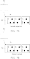
- FIG. 7A is a schematic diagram of the coded image group of the sensing method in accordance with a second embodiment of the present disclosure.
- FIG. 7B is a schematic diagram of the captured image group of the sensing method in accordance with the second embodiment of the present disclosure.
- FIG. 8 is a flow chart of the sensing method in accordance with the second embodiment of the present disclosure.
- the term “comprising” means “including, but not necessarily limited to”; it specifically indicates open-ended inclusion or membership in a so-described combination, group, series, and the like.
- the term “coupled” is defined as connected, whether directly or indirectly through intervening components, and is not necessarily limited to physical connecting. The connecting can be such that the objects are permanently connected or releasably connected.
- FIG. 1 shows a structured light depth sensor 100 of an embodiment of the present disclosure.
- the structured light depth sensor 100 includes a projector 10 , a camera 20 , a processor 30 , and a storage device 40 .
- the processor 30 is electrically connected to the projector 10 , the camera 20 , and the storage device 40 .
- the storage device 40 stores parameter information of the camera 20 , and distance information between the projector 10 and the camera 20 .
- the projector 10 includes a multi-point light source 11 , a diffractive optical element 12 , and a lens 13 .
- the multi-point light source 11 includes a plurality of point light sources 111 .
- the point light sources 111 are arranged in rows and equally spaced apart from each other.
- the diffractive optical element 12 is positioned opposite to the multi-point light source 11 for dividing a light emitted from the multi-point light source 11 into a plurality of beams.
- the lens 13 is positioned between the multi-point light source 11 and the diffractive optical element 12 , and configured for transmitting the light emitted from the multi-point light source 11 .
- the multi-point light source 11 is a vertical-cavity surface-emitting laser.
- the camera 20 is located on one side of the projector 10 .
- a distance between the camera 20 and the projector 10 is defined as B and stored in the storage device 40 as the distance information.
- a focal length of the camera 20 is defined as F and stored in the storage device 40 as the parameter information.
- the processor 30 can control the projector 10 to sequentially project structured lights with different codes to an object 400 , and control the camera 20 to sequentially capture the structured lights reflected by the object 400 .
- a depth of the object 400 can be calculated by the processor 30 according to the parameter information and the distance information stored in the storage device 40 , information of the structured lights projected by the projector 10 , and information of the structured lights captured by the camera 20 .
- the structured light depth sensor 100 can sense the depth of the object 400 as follows.
- the processor 30 controls the projector 10 to project one of the structured lights with a certain code to obtain a coded image 60
- the structured light reflected by the object 400 is captured by the camera 20 to obtain a captured image 70 .
- the captured image 70 is compared with a coding block 61 set in the coded image 60 by the processor 30 to match a capturing block 71 in the captured image 70 .
- a distance between the coding block 61 and an extension line of the projector 10 is defined as x l .
- a distance between the capturing block 71 and an extension line of the camera 20 is defined as x r .
- a disparity ( ⁇ ) of the coding block 61 and the capturing block 71 is equal to difference between x l and x r .
- FIG. 4 shows a sensing method adapted for the structured light depth sensor 100 which includes the following steps:
- the coding block group and the capturing block group are successfully matched.
- FIG. 5A , FIG. 5B , FIG. 5C , and FIG. 6 show a first embodiment of the sensing method.
- a side length of the detecting block 90 is set to be equal to a distance between each two adjacent point light sources 111 . That is, when the size of the detecting block 90 contains one point light source 111 , both the coding block 61 extracted in the coded image 60 according to the size of the detecting block 90 and the capturing block 71 extracted in the captured image 70 according to the size of the detecting block 90 are images containing only one point light source 111 .
- Each of the point light sources 111 is either in a bright state or in a dark state. In FIG. 5A and FIG. 5B , the point light source 111 in the bright state is indicated by a hollow dot, and the point light source 111 in the dark state is indicated by a solid dot.
- the seven point light sources 111 are labeled as a first point light source 111 a , a second point light source 111 b , a third point light source 111 c , a fourth point light source 111 d , a fifth point light source 111 e , a sixth point light source 111 f , and a seventh point light source 111 g .
- a method that the processor 30 obtains the depth of the object 400 by generating three structured lights with different codes is described as follows.
- the processor 30 controls the projector 10 to project a first structured light to the object 400 .
- the first structured light is generated, the first point light source 111 a , the second point light source 111 b , the third point light source 111 c , and the fourth point light source 111 d are in the bright state, the fifth point light source 111 e , the sixth point light source 111 f , and the seventh point light source 111 g are in the dark state.
- the processor 30 controls the camera 20 to capture the first structured light reflected by the object 400 .
- the processor 30 controls the projector 10 to project a second structured light to the object 400 .
- the first point light source 111 a , the second point light source 111 b , the fifth point light source 111 e , and the sixth point light source 111 f are in the bright state
- the third point light source 111 c , the fourth point light source 111 d , and the seventh point light source 111 g are in the dark state.
- the processor 30 controls the camera 20 to capture the second structured light reflected by the object 400 .
- the processor 30 controls the projector 10 to project a third structured light to the object 400 .
- the third structured light is generated, the first point light source 111 a , the third point light source 111 c , the fifth point light source 111 e , and the seventh point light source 111 g are in the bright state, the second point light source 111 b , the fourth point light source 111 d , and the sixth point light source 111 f are in the dark state.
- the processor 30 controls the camera 20 to capture the third structured light reflected by the object 400 .
- the processor 30 matches the coding block group and the capturing block group.
- the processor 30 calculates the disparity ( ⁇ ) and the depth (D) of the object 400 .
- the number of the point light sources 111 is not limited to being seven.
- a minimum number of the projections is defined as n and satisfies the following relationship 2 n-1 ⁇ m ⁇ 2 n .
- a manner of the structured lights generated by the multi-point light source 11 for n times includes: one (or 2 0 ) point light source 111 in the bright state appears at intervals of one (or 2 0 ) point light source 111 in the dark state, two (or 2 1 ) point light sources 111 in the bright states appear at intervals of two (or 2 1 ) point light sources 111 in the dark states . . . 2 n-1 point light sources 111 in the bright states appear at intervals of 2′ n-1 point light sources 111 in the dark states.
- FIG. 7A , FIG. 7B , and FIG. 8 show a second embodiment of the sensing method.
- the sixty-four point light sources 111 are evenly divided into two lines.
- Both the coding block 61 extracted in the coded image 60 according to the size of the detecting block 90 and the capturing block 71 extracted in the captured image 70 according to the size of the detecting block 90 are images containing four point light sources 111 . Since each point light source 111 is either in the bright state or in the dark state, and each coding block 61 (or each capturing block 71 ) contains four point light sources 111 , each image has sixteen (or 2 4 ) different lighting patterns.
- a method that the processor 30 obtains the depth of the object 400 by generating two structured lights with different codes is described as follows.
- the processor 30 controls the projector 10 to project a first structured light to the object 400 .
- the sixty four point light sources 111 are grouped in fours and include sixteen different lighting patterns.
- the processor 30 controls the camera 20 to capture the first structured light reflected by the object 400 .
- the processor 30 controls the projector 10 to project a second structured light to the object 400 .
- the processor 30 controls the projector 10 to project a second structured light to the object 400 .
- thirty two point light sources 111 which are arranged in a row, one point light source 111 in the bright state appears at intervals of one point light source 111 in the dark state, that is, point light sources in the bright states and point light sources in the dark states are arranged alternately.
- the processor 30 controls the camera 20 to capture the second structured light reflected by the object 400 .
- the processor 30 matches the coding block group and the capturing block group.
- the processor 30 calculates the disparity ( ⁇ ) and the depth (D) of the object 400 .
- the number of the point light sources 111 is not limited to being sixty four. In other embodiments, the number of the point light sources 111 used in the sensing method can be less than sixty four, as long as lighting patterns are different from each other when generating the first structured light.
- the process at block S 703 can avoid the case where the lighting state of the first four point light sources 111 and the lighting pattern of the last four point light sources 111 among six consecutive point light sources 111 are same as S 701 .
- the lighting pattern of the point light sources 111 is not limited to what is described in S 703 , where that one point light source 111 in the bright state appears at intervals of one point light source 111 in the dark state, as long as the lighting pattern of the first four point light sources 111 and the lighting pattern of the last four point light sources 111 among six consecutive point light sources 111 are different.
- the present disclosure employs the processor 30 to control the multi-point light source 11 to sequentially project the structured lights with different codes to an object 400 to obtain the coded images 60 , control the camera 20 to sequentially capture the structured lights reflected by the object 400 , and calculate the depth of the object 400 according to the parameter information and the distance information stored in the storage device 40 .
- the present disclosure can reduce the size of the detecting block 90 by equidistant arrangement of the point light sources, thereby improving sensing accuracy.
Landscapes
- Physics & Mathematics (AREA)
- General Physics & Mathematics (AREA)
- Engineering & Computer Science (AREA)
- Computer Vision & Pattern Recognition (AREA)
- Optics & Photonics (AREA)
- Theoretical Computer Science (AREA)
- Length Measuring Devices By Optical Means (AREA)
- Measurement Of Optical Distance (AREA)
Abstract
A structured light depth sensor for sensing a depth of an object, comprises: a projector for projecting structured lights with different codes to the object; a camera located on one side of the projector and configured for capturing the structured lights reflected by the object; a storage device for storing parameter information of the camera and distance information between the projector and the camera; and a processor electrically connected to the projector, the camera, and the storage device. The processor controls the projector to sequentially project the structured lights with different codes to the object, controls the camera to sequentially capture the structured lights reflected by the object, and calculates the depth of the object. A sensing method adapted for the structured light depth sensor is also provided.
Description
The disclosure generally relates to structured light depth sensors.
Structured light depth sensors have been widely used in face recognition, gesture recognition, 3D scanners, and precision machining, and can be divided into time identification and space identification principles. The face recognition and the gesture recognition mostly use the space identification technique to consider the requirement of identification speed and the limitation of sensing distance.
The structured light depth sensor can calculate the depth of an object by using a projector for projecting structured lights onto the object. In prior art, the projector is usually composed of a plurality of point light sources arranged irregularly, which is not easily obtained, and the size of a block set for detecting and calculating the depth of the object is too large, resulting in low accuracy. Therefore, there is room for improvement within the art.
Many aspects of the present disclosure can be better understood with reference to the drawings. The components in the drawings are not necessarily drawn to scale, the emphasis instead being placed upon clearly illustrating the principles of the disclosure. Moreover, in the drawings, like reference numerals designate corresponding parts throughout the views.
It will be appreciated that for simplicity and clarity of illustration, numerous specific details are set forth in order to provide a thorough understanding of the embodiments described herein. However, it will be understood by those of ordinary skill in the art that the embodiments described herein can be practiced without these specific details. In other instances, methods, procedures, and components have not been described in detail so as not to obscure the related relevant feature being described. The drawings are not necessarily to scale and the proportions of certain parts have been exaggerated to better illustrate details and features of the present disclosure. The description is not to be considered as limiting the scope of the embodiments described herein.
Several definitions that apply throughout this disclosure will now be presented. The term “comprising” means “including, but not necessarily limited to”; it specifically indicates open-ended inclusion or membership in a so-described combination, group, series, and the like. The term “coupled” is defined as connected, whether directly or indirectly through intervening components, and is not necessarily limited to physical connecting. The connecting can be such that the objects are permanently connected or releasably connected.
As shown in FIG. 2A and FIG. 2B , the projector 10 includes a multi-point light source 11, a diffractive optical element 12, and a lens 13. The multi-point light source 11 includes a plurality of point light sources 111. The point light sources 111 are arranged in rows and equally spaced apart from each other. The diffractive optical element 12 is positioned opposite to the multi-point light source 11 for dividing a light emitted from the multi-point light source 11 into a plurality of beams. The lens 13 is positioned between the multi-point light source 11 and the diffractive optical element 12, and configured for transmitting the light emitted from the multi-point light source 11. In at least one embodiment, the multi-point light source 11 is a vertical-cavity surface-emitting laser.
As shown in FIG. 3 , the camera 20 is located on one side of the projector 10. A distance between the camera 20 and the projector 10 is defined as B and stored in the storage device 40 as the distance information. A focal length of the camera 20 is defined as F and stored in the storage device 40 as the parameter information. The processor 30 can control the projector 10 to sequentially project structured lights with different codes to an object 400, and control the camera 20 to sequentially capture the structured lights reflected by the object 400. A depth of the object 400 can be calculated by the processor 30 according to the parameter information and the distance information stored in the storage device 40, information of the structured lights projected by the projector 10, and information of the structured lights captured by the camera 20.
The structured light depth sensor 100 can sense the depth of the object 400 as follows. When the processor 30 controls the projector 10 to project one of the structured lights with a certain code to obtain a coded image 60, the structured light reflected by the object 400 is captured by the camera 20 to obtain a captured image 70. The captured image 70 is compared with a coding block 61 set in the coded image 60 by the processor 30 to match a capturing block 71 in the captured image 70. A distance between the coding block 61 and an extension line of the projector 10 is defined as xl. A distance between the capturing block 71 and an extension line of the camera 20 is defined as xr. A disparity (δ) of the coding block 61 and the capturing block 71 is equal to difference between xl and xr. The processor 30 calculates the depth (D) of the object 400 according to the following formula D=B*F/δ.
S401, setting a detecting block 90;
S402, generating the structured lights with different codes;
S403, sequentially projecting the structured lights with different codes to the object 400 to obtain a plurality of coded images 60;
S404, capturing the structured lights reflected by the object 400 to obtain a plurality of captured images 70;
S405, integrating the plurality of coded images 60 into a coded image group according to a projection order, and integrating the plurality of camera images 70 into a captured image group according to a capture order;
S406, extracting the coding block 61 in each of the plurality of coded images 60 according to the position and size of the detecting block 90;
S407, integrating a plurality of coding blocks 61 into a coding block group in a same order as the coded image group;
S408, extracting the capturing block 71 in each of the plurality of captured images 70 according to the position and size of the detecting block 90;
S409, integrating a plurality of capturing blocks 71 into a capturing block group in a same order as the captured image group;
S410, matching the coding block group and the capturing block group;
S411, calculating the disparity between the coding block group and the capturing block group matched with the coding block group;
S412, calculating the depth of the object 400.
Specifically, if images of the coding block group and the capturing block group are in a same order, the coding block group and the capturing block group are successfully matched.
In the first embodiment, there are seven point light sources 111. The seven point light sources 111 are labeled as a first point light source 111 a, a second point light source 111 b, a third point light source 111 c, a fourth point light source 111 d, a fifth point light source 111 e, a sixth point light source 111 f, and a seventh point light source 111 g. A method that the processor 30 obtains the depth of the object 400 by generating three structured lights with different codes is described as follows.
S501, the processor 30 controls the projector 10 to project a first structured light to the object 400. When the first structured light is generated, the first point light source 111 a, the second point light source 111 b, the third point light source 111 c, and the fourth point light source 111 d are in the bright state, the fifth point light source 111 e, the sixth point light source 111 f, and the seventh point light source 111 g are in the dark state.
S502, the processor 30 controls the camera 20 to capture the first structured light reflected by the object 400.
S503, the processor 30 controls the projector 10 to project a second structured light to the object 400. When the second structured light is generated, the first point light source 111 a, the second point light source 111 b, the fifth point light source 111 e, and the sixth point light source 111 f are in the bright state, the third point light source 111 c, the fourth point light source 111 d, and the seventh point light source 111 g are in the dark state.
S504, the processor 30 controls the camera 20 to capture the second structured light reflected by the object 400.
S505, the processor 30 controls the projector 10 to project a third structured light to the object 400. When the third structured light is generated, the first point light source 111 a, the third point light source 111 c, the fifth point light source 111 e, and the seventh point light source 111 g are in the bright state, the second point light source 111 b, the fourth point light source 111 d, and the sixth point light source 111 f are in the dark state.
S506, the processor 30 controls the camera 20 to capture the third structured light reflected by the object 400.
S507, the processor 30 matches the coding block group and the capturing block group.
S508, the processor 30 calculates the disparity (δ) and the depth (D) of the object 400.
The number of the point light sources 111 is not limited to being seven. When the number of the point light sources 111 is defined as m (m≥2), a minimum number of the projections is defined as n and satisfies the following relationship 2n-1≤m≤2n. A manner of the structured lights generated by the multi-point light source 11 for n times includes: one (or 20) point light source 111 in the bright state appears at intervals of one (or 20) point light source 111 in the dark state, two (or 21) point light sources 111 in the bright states appear at intervals of two (or 21) point light sources 111 in the dark states . . . 2n-1 point light sources 111 in the bright states appear at intervals of 2′n-1 point light sources 111 in the dark states.
S701, the processor 30 controls the projector 10 to project a first structured light to the object 400. The sixty four point light sources 111 are grouped in fours and include sixteen different lighting patterns.
S702, the processor 30 controls the camera 20 to capture the first structured light reflected by the object 400.
S703, the processor 30 controls the projector 10 to project a second structured light to the object 400. Among thirty two point light sources 111, which are arranged in a row, one point light source 111 in the bright state appears at intervals of one point light source 111 in the dark state, that is, point light sources in the bright states and point light sources in the dark states are arranged alternately.
S704, the processor 30 controls the camera 20 to capture the second structured light reflected by the object 400.
S705, the processor 30 matches the coding block group and the capturing block group.
S706, the processor 30 calculates the disparity (δ) and the depth (D) of the object 400.
The number of the point light sources 111 is not limited to being sixty four. In other embodiments, the number of the point light sources 111 used in the sensing method can be less than sixty four, as long as lighting patterns are different from each other when generating the first structured light.
The process at block S703 can avoid the case where the lighting state of the first four point light sources 111 and the lighting pattern of the last four point light sources 111 among six consecutive point light sources 111 are same as S701. It should be noted that the lighting pattern of the point light sources 111 is not limited to what is described in S703, where that one point light source 111 in the bright state appears at intervals of one point light source 111 in the dark state, as long as the lighting pattern of the first four point light sources 111 and the lighting pattern of the last four point light sources 111 among six consecutive point light sources 111 are different.
Compared with the prior art, the present disclosure employs the processor 30 to control the multi-point light source 11 to sequentially project the structured lights with different codes to an object 400 to obtain the coded images 60, control the camera 20 to sequentially capture the structured lights reflected by the object 400, and calculate the depth of the object 400 according to the parameter information and the distance information stored in the storage device 40. The present disclosure can reduce the size of the detecting block 90 by equidistant arrangement of the point light sources, thereby improving sensing accuracy.
It is believed that the present embodiments and their advantages will be understood from the foregoing description, and it will be apparent that various changes may be made thereto without departing from the spirit and scope of the disclosure or sacrificing all of its material advantages, the examples hereinbefore described merely being exemplary embodiments of the present disclosure.
Claims (18)
1. A structured light depth sensor for sensing a depth of an object, comprising:
a projector for projecting structured lights with different codes to the object;
a camera located on one side of the projector and configured for capturing the structured lights reflected by the object;
a storage device for storing parameter information of the camera and distance information between the projector and the camera; and
a processor electrically connected to the projector, the camera, and the storage device, wherein, the processor controls the projector to sequentially project the structured lights with different codes to the object, controls the camera to sequentially capture the structured lights reflected by the object, and calculates the depth of the object according to the parameter information of the camera, the distance information between the projector and the camera, information of the structured lights projected by the projector, and information of the structured lights captured by the camera;
wherein a coded image is obtained when the processor controls the projector to project one of the structured lights with a certain code, and a captured image is obtained when the camera captures the structured light with the certain code reflected by the object; and
wherein the captured image is compared with a coding block set in the coded image by the processor to match a capturing block, a disparity (δ) of the coding block and the capturing block is calculated by the processor and is equal to a difference between xl and xr, where xl represents a distance between the coding block and an extension line of the projector, and xr represent a distance between the capturing block and an extension line of the camera.
2. The structured light depth sensor as claimed in claim 1 , wherein the depth (D) of the object is calculated by the processor according to the following formula: D=B*F/δ, where B represents a distance between the camera and the projector that stored in the storage device as the distance information, and F represents a focal length of the camera that stored in the storage device as the parameter information.
3. The structured light depth sensor as claimed in claim 1 , wherein the projector comprises a multi-point light source comprising a plurality of point light sources, the point light sources are arranged in rows and equally spaced apart from each other, and each of the plurality of point light sources is either in a bright state or in a dark state.
4. The structured light depth sensor as claimed in claim 3 , wherein the multi-point light source is a vertical-cavity surface-emitting laser.
5. The structured light depth sensor as claimed in claim 3 , wherein the projector further comprises a diffractive optical element positioned opposite to the multi-point light source, and configured for dividing a light emitted from the multi-point light source into a plurality of beams.
6. The structured light depth sensor as claimed in claim 5 , wherein the projector further comprises a lens positioned between the multi-point light source and the diffractive optical element, and configured for transmitting the light emitted from the multi-point light source.
7. A sensing method, adapted for a structured light depth sensor, the structured light depth sensor comprising a projector, a camera, a processor, and a storage device, the sensing method comprising:
generating structured lights with different codes;
sequentially projecting the structured lights to an object to obtain a plurality of coded images;
capturing the structured lights reflected by the object to obtain a plurality of captured images;
integrating the plurality of coded images into a coded image group according to a projection order, and integrating the plurality of camera images into a captured image group according to a capture order;
setting a detecting block;
extracting a coding block in each of the plurality of coded images according to the position and size of the detecting block;
integrating a plurality of coding blocks into a coding block group in a same order as the coded image group;
extracting a capturing block in each of the plurality of captured images according to the position and size of the detecting block;
integrating a plurality of capturing blocks into a capturing block group in a same order as the captured image group;
matching the coding block group and the capturing block group;
calculating a disparity between the coding block group and the capturing block group matched with the coding block group; and
calculating a depth of the object.
8. The sensing method as claimed in claim 7 , wherein if images of the coding block group and the capturing block group are in a same order, the coding block group and the capturing block group are successfully matched.
9. The sensing method as claimed in claim 8 , wherein the processor controls the projector to sequentially project the structured lights with different codes to the object and controls the camera to sequentially capture the structured lights reflected by the object, the storage device stores parameter information of the camera and distance information between the projector and the camera, and the processor calculates the depth of the object according to the parameter information of the camera, the distance information between the projector and the camera, information of the structured lights projected by the projector, and information of the structured lights captured by the camera.
10. The sensing method as claimed in claim 9 , wherein the projector comprises a multi-point light source comprising a plurality of point light sources, the point light sources are arranged in rows and equally spaced apart from each other, and each of the plurality of point light sources is either in a bright state or in a dark state.
11. The sensing method as claimed in claim 10 , wherein the projector further comprises a diffractive optical element positioned opposite to the multi-point light source, and configured for dividing a light emitted from the multi-point light source into a plurality of beams.
12. The sensing method as claimed in claim 11 , wherein the projector further comprises a lens positioned between the multi-point light source and the diffractive optical element, and configured for transmitting the light emitted from the multi-point light source.
13. The sensing method as claimed in claim 9 , wherein the depth (D) of the object is calculated by the processor according to the following formula: D=B*F/δ, where B represents a distance between the camera and the projector that stored in the storage device as the distance information, F represents a focal length of the camera that stored in the storage device as the parameter information, and δ represents a disparity of the coding block and the capturing block.
14. The sensing method as claimed in claim 13 , wherein the disparity of the coding block and the capturing block is calculated by the processor and is equal to a difference between xl and xr where xl represents a distance between the coding block and an extension line of the projector, and xr represents a distance between the capturing block and an extension line of the camera.
15. The sensing method as claimed in claim 10 , wherein when the size of the detecting block contains one point light source, a number of the point light sources (m) and a minimum number (n) of the projections satisfy the following relationship: 2n-1≤m≤2n, m≥2.
16. The sensing method as claimed in claim 15 , wherein a manner of the structured lights generated by the multi-point light source for n times comprises: one (or 20) point light source in the bright state appears at intervals of one (or 20) point light source in the dark state, two (or 21) point light sources in the bright states appear at intervals of two (or 21) point light sources in the dark states . . . 2n-1 point light sources in the bright states appear at intervals of 2n-1 point light sources in the dark states.
17. The sensing method as claimed in claim 12 , wherein the point light sources are evenly divided into two rows, when the size of the detecting block contains four point light sources arranged in a matrix, both the coding block and the capturing block are images containing four point light sources, and each image has sixteen different lighting patterns.
18. The sensing method as claimed in claim 17 , wherein a number of the point light sources is sixty four, the processor controls the projector projecting two structured lights with different codes to the object, a first structured light contains the sixteen different lighting patterns, a second structured light satisfies a condition that the lighting pattern of the first four point light sources and the lighting pattern of the last four point light sources among six consecutive point light sources are different.
Applications Claiming Priority (2)
| Application Number | Priority Date | Filing Date | Title |
|---|---|---|---|
| CN201811331270.5A CN109470166B (en) | 2018-11-09 | 2018-11-09 | Structured light depth sensor and sensing method |
| CN201811331270 | 2018-11-09 |
Publications (1)
| Publication Number | Publication Date |
|---|---|
| US10540774B1 true US10540774B1 (en) | 2020-01-21 |
Family
ID=65671872
Family Applications (1)
| Application Number | Title | Priority Date | Filing Date |
|---|---|---|---|
| US16/285,499 Active US10540774B1 (en) | 2018-11-09 | 2019-02-26 | Structured light depth sensor and sensing method thereof |
Country Status (3)
| Country | Link |
|---|---|
| US (1) | US10540774B1 (en) |
| CN (1) | CN109470166B (en) |
| TW (1) | TWI699733B (en) |
Cited By (2)
| Publication number | Priority date | Publication date | Assignee | Title |
|---|---|---|---|---|
| WO2021039022A1 (en) * | 2019-08-27 | 2021-03-04 | Sony Corporation | Ranging system and electronic apparatus |
| CN116980574A (en) * | 2022-04-13 | 2023-10-31 | 深微光电科技(深圳)有限公司 | A uniform high frame rate projection control circuit, method and industrial optical machine |
Families Citing this family (2)
| Publication number | Priority date | Publication date | Assignee | Title |
|---|---|---|---|---|
| CN110174075B (en) * | 2019-04-08 | 2020-11-03 | 深圳奥比中光科技有限公司 | Single-zoom-structure optical depth camera and zooming method |
| CN114494390B (en) * | 2021-12-31 | 2025-12-16 | 奥比中光科技集团股份有限公司 | Depth data determining method, device, terminal and storage medium |
Citations (27)
| Publication number | Priority date | Publication date | Assignee | Title |
|---|---|---|---|---|
| US20040005092A1 (en) * | 2002-06-19 | 2004-01-08 | Carlo Tomasi | Coded-array technique for obtaining depth and other position information of an observed object |
| US20100074532A1 (en) * | 2006-11-21 | 2010-03-25 | Mantisvision Ltd. | 3d geometric modeling and 3d video content creation |
| US7852461B2 (en) * | 2007-11-15 | 2010-12-14 | Microsoft International Holdings B.V. | Dual mode depth imaging |
| US8896594B2 (en) * | 2012-06-30 | 2014-11-25 | Microsoft Corporation | Depth sensing with depth-adaptive illumination |
| US20160255332A1 (en) * | 2015-02-27 | 2016-09-01 | Qualcomm Incorporated | Systems and methods for error correction in structured light |
| US20160261852A1 (en) * | 2013-12-16 | 2016-09-08 | Sony Corporation | Image processing device, image processing method, and imaging device |
| US9445081B1 (en) * | 2015-09-25 | 2016-09-13 | Intel Corporation | Method and system of 3D image capture with dynamic cameras |
| US9530215B2 (en) * | 2015-03-20 | 2016-12-27 | Qualcomm Incorporated | Systems and methods for enhanced depth map retrieval for moving objects using active sensing technology |
| US20170186167A1 (en) * | 2015-12-26 | 2017-06-29 | Intel Corporation | Stereodepth camera using vcsel projector with controlled projection lens |
| US20170195656A1 (en) * | 2016-01-04 | 2017-07-06 | Qualcomm Incorporated | Depth map generation in structured light system |
| US9712806B2 (en) * | 2014-12-19 | 2017-07-18 | Datalogic ADC, Inc. | Depth camera system using coded structured light |
| US9800859B2 (en) * | 2013-03-15 | 2017-10-24 | Fotonation Cayman Limited | Systems and methods for estimating depth using stereo array cameras |
| US20170337703A1 (en) * | 2016-05-17 | 2017-11-23 | Wistron Corporation | Method and system for generating depth information |
| US9872012B2 (en) * | 2014-07-04 | 2018-01-16 | Samsung Electronics Co., Ltd. | Method and apparatus for image capturing and simultaneous depth extraction |
| US20180020195A1 (en) * | 2016-07-15 | 2018-01-18 | Qualcomm Incorporated | Object reconstruction in disparity maps using displaced shadow outlines |
| US20180059679A1 (en) * | 2016-09-01 | 2018-03-01 | Ford Global Technologies, Llc | Depth map estimation with stereo images |
| US9916524B2 (en) * | 2016-02-17 | 2018-03-13 | Microsoft Technology Licensing, Llc | Determining depth from structured light using trained classifiers |
| US10068338B2 (en) * | 2015-03-12 | 2018-09-04 | Qualcomm Incorporated | Active sensing spatial resolution improvement through multiple receivers and code reuse |
| US20180321384A1 (en) * | 2017-05-05 | 2018-11-08 | Qualcomm Incorporated | Systems and methods for generating a structured light depth map with a non-uniform codeword pattern |
| US10192311B2 (en) * | 2016-08-05 | 2019-01-29 | Qualcomm Incorporated | Methods and apparatus for codeword boundary detection for generating depth maps |
| US10194138B2 (en) * | 2015-08-18 | 2019-01-29 | RGBDsense Information Technology Ltd. | Structured light encoding-based vertical depth perception apparatus |
| US20190045173A1 (en) * | 2017-12-19 | 2019-02-07 | Intel Corporation | Dynamic vision sensor and projector for depth imaging |
| US20190064359A1 (en) * | 2017-08-29 | 2019-02-28 | Shenzhen GOODIX Technology Co., Ltd. | Optical Distance Measuring Method and Optical Distance Measuring Device |
| US20190089939A1 (en) * | 2017-09-18 | 2019-03-21 | Intel Corporation | Depth sensor optimization based on detected distance |
| US20190101382A1 (en) * | 2017-09-27 | 2019-04-04 | Brown Univ ersity | Techniques for shape measurement using high frequency patterns and related systems and methods |
| US20190122378A1 (en) * | 2017-04-17 | 2019-04-25 | The United States Of America, As Represented By The Secretary Of The Navy | Apparatuses and methods for machine vision systems including creation of a point cloud model and/or three dimensional model based on multiple images from different perspectives and combination of depth cues from camera motion and defocus with various applications including navigation systems, and pattern matching systems as well as estimating relative blur between images for use in depth from defocus or autofocusing applications |
| US20190213746A1 (en) * | 2018-01-05 | 2019-07-11 | Panasonic Intellectual Property Management Co., Ltd. | Disparity estimation device, disparity estimation method, and program |
Family Cites Families (12)
| Publication number | Priority date | Publication date | Assignee | Title |
|---|---|---|---|---|
| WO2003046640A1 (en) * | 2001-11-27 | 2003-06-05 | Matsushita Electric Industrial Co., Ltd. | Single-panel projection type image display apparatus |
| WO2004005855A2 (en) * | 2002-07-08 | 2004-01-15 | Microe Systems Corporation | Multi-track optical encoder employing beam divider |
| CA2993711C (en) * | 2009-05-01 | 2021-01-26 | Garrett Thermal Systems Limited | Improvements to particle detectors |
| US9014848B2 (en) * | 2010-05-20 | 2015-04-21 | Irobot Corporation | Mobile robot system |
| CN101961698B (en) * | 2010-08-04 | 2013-02-13 | 中国科学院自动化研究所 | Device and method for measuring poses of embedded type spraying gun in real time |
| CN102760234B (en) * | 2011-04-14 | 2014-08-20 | 财团法人工业技术研究院 | Depth image acquisition device, system and method |
| CN103245641B (en) * | 2012-02-10 | 2014-10-29 | 清华大学 | Multi-channel planar waveguide evanescent wave biosensor |
| CN104359405B (en) * | 2014-11-27 | 2017-11-07 | 上海集成电路研发中心有限公司 | Three-dimensional scanner |
| US9992474B2 (en) * | 2015-12-26 | 2018-06-05 | Intel Corporation | Stereo depth camera using VCSEL with spatially and temporally interleaved patterns |
| CN108592788B (en) * | 2018-03-29 | 2020-07-24 | 湖南大学 | A 3D intelligent camera system and workpiece online measurement method for spraying production line |
| CN208013572U (en) * | 2018-04-08 | 2018-10-26 | 迪鹏光电科技股份有限公司 | Multi-point source pattern projector |
| CN108718406B (en) * | 2018-05-31 | 2020-04-03 | 西安知微传感技术有限公司 | Variable-focus 3D depth camera and imaging method thereof |
-
2018
- 2018-11-09 CN CN201811331270.5A patent/CN109470166B/en not_active Expired - Fee Related
- 2018-11-26 TW TW107141979A patent/TWI699733B/en active
-
2019
- 2019-02-26 US US16/285,499 patent/US10540774B1/en active Active
Patent Citations (28)
| Publication number | Priority date | Publication date | Assignee | Title |
|---|---|---|---|---|
| US7212663B2 (en) * | 2002-06-19 | 2007-05-01 | Canesta, Inc. | Coded-array technique for obtaining depth and other position information of an observed object |
| US20040005092A1 (en) * | 2002-06-19 | 2004-01-08 | Carlo Tomasi | Coded-array technique for obtaining depth and other position information of an observed object |
| US20100074532A1 (en) * | 2006-11-21 | 2010-03-25 | Mantisvision Ltd. | 3d geometric modeling and 3d video content creation |
| US7852461B2 (en) * | 2007-11-15 | 2010-12-14 | Microsoft International Holdings B.V. | Dual mode depth imaging |
| US8896594B2 (en) * | 2012-06-30 | 2014-11-25 | Microsoft Corporation | Depth sensing with depth-adaptive illumination |
| US9800859B2 (en) * | 2013-03-15 | 2017-10-24 | Fotonation Cayman Limited | Systems and methods for estimating depth using stereo array cameras |
| US20160261852A1 (en) * | 2013-12-16 | 2016-09-08 | Sony Corporation | Image processing device, image processing method, and imaging device |
| US9872012B2 (en) * | 2014-07-04 | 2018-01-16 | Samsung Electronics Co., Ltd. | Method and apparatus for image capturing and simultaneous depth extraction |
| US9712806B2 (en) * | 2014-12-19 | 2017-07-18 | Datalogic ADC, Inc. | Depth camera system using coded structured light |
| US20160255332A1 (en) * | 2015-02-27 | 2016-09-01 | Qualcomm Incorporated | Systems and methods for error correction in structured light |
| US10068338B2 (en) * | 2015-03-12 | 2018-09-04 | Qualcomm Incorporated | Active sensing spatial resolution improvement through multiple receivers and code reuse |
| US9530215B2 (en) * | 2015-03-20 | 2016-12-27 | Qualcomm Incorporated | Systems and methods for enhanced depth map retrieval for moving objects using active sensing technology |
| US10194138B2 (en) * | 2015-08-18 | 2019-01-29 | RGBDsense Information Technology Ltd. | Structured light encoding-based vertical depth perception apparatus |
| US9445081B1 (en) * | 2015-09-25 | 2016-09-13 | Intel Corporation | Method and system of 3D image capture with dynamic cameras |
| US20170186167A1 (en) * | 2015-12-26 | 2017-06-29 | Intel Corporation | Stereodepth camera using vcsel projector with controlled projection lens |
| US20170195656A1 (en) * | 2016-01-04 | 2017-07-06 | Qualcomm Incorporated | Depth map generation in structured light system |
| US9916524B2 (en) * | 2016-02-17 | 2018-03-13 | Microsoft Technology Licensing, Llc | Determining depth from structured light using trained classifiers |
| US20170337703A1 (en) * | 2016-05-17 | 2017-11-23 | Wistron Corporation | Method and system for generating depth information |
| US20180020195A1 (en) * | 2016-07-15 | 2018-01-18 | Qualcomm Incorporated | Object reconstruction in disparity maps using displaced shadow outlines |
| US10192311B2 (en) * | 2016-08-05 | 2019-01-29 | Qualcomm Incorporated | Methods and apparatus for codeword boundary detection for generating depth maps |
| US20180059679A1 (en) * | 2016-09-01 | 2018-03-01 | Ford Global Technologies, Llc | Depth map estimation with stereo images |
| US20190122378A1 (en) * | 2017-04-17 | 2019-04-25 | The United States Of America, As Represented By The Secretary Of The Navy | Apparatuses and methods for machine vision systems including creation of a point cloud model and/or three dimensional model based on multiple images from different perspectives and combination of depth cues from camera motion and defocus with various applications including navigation systems, and pattern matching systems as well as estimating relative blur between images for use in depth from defocus or autofocusing applications |
| US20180321384A1 (en) * | 2017-05-05 | 2018-11-08 | Qualcomm Incorporated | Systems and methods for generating a structured light depth map with a non-uniform codeword pattern |
| US20190064359A1 (en) * | 2017-08-29 | 2019-02-28 | Shenzhen GOODIX Technology Co., Ltd. | Optical Distance Measuring Method and Optical Distance Measuring Device |
| US20190089939A1 (en) * | 2017-09-18 | 2019-03-21 | Intel Corporation | Depth sensor optimization based on detected distance |
| US20190101382A1 (en) * | 2017-09-27 | 2019-04-04 | Brown Univ ersity | Techniques for shape measurement using high frequency patterns and related systems and methods |
| US20190045173A1 (en) * | 2017-12-19 | 2019-02-07 | Intel Corporation | Dynamic vision sensor and projector for depth imaging |
| US20190213746A1 (en) * | 2018-01-05 | 2019-07-11 | Panasonic Intellectual Property Management Co., Ltd. | Disparity estimation device, disparity estimation method, and program |
Cited By (3)
| Publication number | Priority date | Publication date | Assignee | Title |
|---|---|---|---|---|
| WO2021039022A1 (en) * | 2019-08-27 | 2021-03-04 | Sony Corporation | Ranging system and electronic apparatus |
| US12149840B2 (en) | 2019-08-27 | 2024-11-19 | Sony Group Corporation | Ranging system and electronic apparatus |
| CN116980574A (en) * | 2022-04-13 | 2023-10-31 | 深微光电科技(深圳)有限公司 | A uniform high frame rate projection control circuit, method and industrial optical machine |
Also Published As
| Publication number | Publication date |
|---|---|
| CN109470166B (en) | 2020-12-08 |
| CN109470166A (en) | 2019-03-15 |
| TW202018663A (en) | 2020-05-16 |
| TWI699733B (en) | 2020-07-21 |
Similar Documents
| Publication | Publication Date | Title |
|---|---|---|
| US10540774B1 (en) | Structured light depth sensor and sensing method thereof | |
| US10041787B2 (en) | Object detection device | |
| CN108933850B (en) | mobile terminal | |
| CN109086694B (en) | Face recognition system and method | |
| US10068348B2 (en) | Method and apparatus for indentifying structural elements of a projected structural pattern in camera images | |
| US20160279809A1 (en) | Information processing apparatus, and information processing method | |
| US8705013B2 (en) | Diffractive optical element, distance measuring apparatus and distance measuring method | |
| US20170193317A1 (en) | Living body identification device, living body identification method and living body authentication system | |
| CN107121072B (en) | 2D Absolute Displacement Encoder | |
| CN103544461A (en) | Handheld apparatus for quantifying component features | |
| CN101598299A (en) | Light source module and game device using the light source module | |
| TW201935910A (en) | Apparatus and method for processing three dimensional images | |
| US9031694B2 (en) | Entry detection device, robot, and entry detection method | |
| US20120293626A1 (en) | Three-dimensional distance measurement system for reconstructing three-dimensional image using code line | |
| CN108428244A (en) | Image matching method and depth data measurement method and system | |
| CN111757010A (en) | Active optical rigid body configuration method, system and terminal equipment | |
| JP2014199193A (en) | Three-dimensional measuring device, three-dimensional measuring method, and program | |
| CN114820939B (en) | Image reconstruction method, device and equipment | |
| RU2199718C1 (en) | DEVICE FOR CONTROLLING and RECOGNIZING THREE-DIMENSIONAL OBJECTS SURFACES IN CONTACTLESS WAY | |
| JP2002027501A (en) | Three-dimensional image pickup device and method | |
| TWI634515B (en) | Apparatus and method for processing three dimensional image | |
| CN111914716B (en) | Active light rigid body identification method, device, equipment and storage medium | |
| CN116746144A (en) | camera module | |
| JP2011133360A (en) | Distance measuring device, distance measurement method, and program | |
| US10595007B2 (en) | Structured-light method and system of dynamically generating a depth map |
Legal Events
| Date | Code | Title | Description |
|---|---|---|---|
| FEPP | Fee payment procedure |
Free format text: ENTITY STATUS SET TO UNDISCOUNTED (ORIGINAL EVENT CODE: BIG.); ENTITY STATUS OF PATENT OWNER: LARGE ENTITY |
|
| STCF | Information on status: patent grant |
Free format text: PATENTED CASE |
|
| MAFP | Maintenance fee payment |
Free format text: PAYMENT OF MAINTENANCE FEE, 4TH YEAR, LARGE ENTITY (ORIGINAL EVENT CODE: M1551); ENTITY STATUS OF PATENT OWNER: LARGE ENTITY Year of fee payment: 4 |