US10539723B2 - Phase-transforming optical reflector formed by partial etching or by partial etching with reflow - Google Patents
Phase-transforming optical reflector formed by partial etching or by partial etching with reflow Download PDFInfo
- Publication number
- US10539723B2 US10539723B2 US15/784,702 US201715784702A US10539723B2 US 10539723 B2 US10539723 B2 US 10539723B2 US 201715784702 A US201715784702 A US 201715784702A US 10539723 B2 US10539723 B2 US 10539723B2
- Authority
- US
- United States
- Prior art keywords
- optical element
- reflective surface
- areas
- recessed
- reflective
- Prior art date
- Legal status (The legal status is an assumption and is not a legal conclusion. Google has not performed a legal analysis and makes no representation as to the accuracy of the status listed.)
- Active, expires
Links
Images


Classifications
-
- G—PHYSICS
- G02—OPTICS
- G02B—OPTICAL ELEMENTS, SYSTEMS OR APPARATUS
- G02B5/00—Optical elements other than lenses
- G02B5/08—Mirrors
- G02B5/0883—Mirrors with a refractive index gradient
-
- G—PHYSICS
- G02—OPTICS
- G02B—OPTICAL ELEMENTS, SYSTEMS OR APPARATUS
- G02B3/00—Simple or compound lenses
- G02B3/02—Simple or compound lenses with non-spherical faces
- G02B3/08—Simple or compound lenses with non-spherical faces with discontinuous faces, e.g. Fresnel lens
-
- G—PHYSICS
- G02—OPTICS
- G02B—OPTICAL ELEMENTS, SYSTEMS OR APPARATUS
- G02B5/00—Optical elements other than lenses
- G02B5/18—Diffraction gratings
- G02B5/1847—Manufacturing methods
-
- G—PHYSICS
- G02—OPTICS
- G02B—OPTICAL ELEMENTS, SYSTEMS OR APPARATUS
- G02B5/00—Optical elements other than lenses
- G02B5/18—Diffraction gratings
- G02B5/1861—Reflection gratings characterised by their structure, e.g. step profile, contours of substrate or grooves, pitch variations, materials
-
- G—PHYSICS
- G02—OPTICS
- G02B—OPTICAL ELEMENTS, SYSTEMS OR APPARATUS
- G02B5/00—Optical elements other than lenses
- G02B5/18—Diffraction gratings
- G02B5/1866—Transmission gratings characterised by their structure, e.g. step profile, contours of substrate or grooves, pitch variations, materials
- G02B5/1871—Transmissive phase gratings
-
- G—PHYSICS
- G02—OPTICS
- G02B—OPTICAL ELEMENTS, SYSTEMS OR APPARATUS
- G02B5/00—Optical elements other than lenses
- G02B5/30—Polarising elements
- G02B5/3083—Birefringent or phase retarding elements
-
- C—CHEMISTRY; METALLURGY
- C23—COATING METALLIC MATERIAL; COATING MATERIAL WITH METALLIC MATERIAL; CHEMICAL SURFACE TREATMENT; DIFFUSION TREATMENT OF METALLIC MATERIAL; COATING BY VACUUM EVAPORATION, BY SPUTTERING, BY ION IMPLANTATION OR BY CHEMICAL VAPOUR DEPOSITION, IN GENERAL; INHIBITING CORROSION OF METALLIC MATERIAL OR INCRUSTATION IN GENERAL
- C23F—NON-MECHANICAL REMOVAL OF METALLIC MATERIAL FROM SURFACE; INHIBITING CORROSION OF METALLIC MATERIAL OR INCRUSTATION IN GENERAL; MULTI-STEP PROCESSES FOR SURFACE TREATMENT OF METALLIC MATERIAL INVOLVING AT LEAST ONE PROCESS PROVIDED FOR IN CLASS C23 AND AT LEAST ONE PROCESS COVERED BY SUBCLASS C21D OR C22F OR CLASS C25
- C23F1/00—Etching metallic material by chemical means
- C23F1/02—Local etching
-
- H—ELECTRICITY
- H01—ELECTRIC ELEMENTS
- H01J—ELECTRIC DISCHARGE TUBES OR DISCHARGE LAMPS
- H01J37/00—Discharge tubes with provision for introducing objects or material to be exposed to the discharge, e.g. for the purpose of examination or processing thereof
- H01J37/30—Electron-beam or ion-beam tubes for localised treatment of objects
- H01J37/305—Electron-beam or ion-beam tubes for localised treatment of objects for casting, melting, evaporating, or etching
- H01J37/3053—Electron-beam or ion-beam tubes for localised treatment of objects for casting, melting, evaporating, or etching for evaporating or etching
- H01J37/3056—Electron-beam or ion-beam tubes for localised treatment of objects for casting, melting, evaporating, or etching for evaporating or etching for microworking, e. g. etching of gratings or trimming of electrical components
Definitions
- the field of the present invention relates to phase-transforming optical reflectors.
- methods are disclosed for making such optical reflectors using partial etching or using partial etching with reflow.
- An inventive optical element comprises a reflective surface supported by a substantially solid substrate; the reflective surface comprises a multitude of discrete recessed and non-recessed areas arranged contiguously along the reflective surface.
- the recessed or non-recessed areas include a non-empty subset of areas of the multitude having a largest transverse dimension less than about a design vacuum wavelength ⁇ 0 .
- the recessed and non-recessed areas are characterized by a depth function d(x,y), which is a function of two-dimensional position coordinates x and y along the reflective surface, that equals zero in the non-recessed areas and that assumes non-zero values in the recessed areas up to a maximum depth D R .
- the reflective surface is reflective over an operational wavelength range that includes the design vacuum wavelength ⁇ 0 ; a corresponding volume within each recessed area is substantially transparent over the operational wavelength range and is characterized by a first bulk refractive index n 1 ( ⁇ ).
- the optical element is structurally arranged so as to receive an optical signal incident on the reflective surface and to reflect at least a portion of the incident optical signal transformed substantially according to a specified effective phase transformation function ⁇ eff (x,y) that varies as a function of x and y.
- the discrete areas of the multitude are variously sized and distributed on the reflective surface so as to impart on the reflected portion of the incident optical signal the effective phase transformation ⁇ eff (x,y).
- Inventive methods for making an inventive optical element include spatially selectively processing a surface or layer of material to form the recessed and non-recessed areas, and can further include a calibration process, an iterative fabrication process, or a reflow process.
- phase-transforming optical reflectors may become apparent upon referring to the example embodiments illustrated in the drawings and disclosed in the following written description or appended claims.
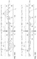
- FIGS. 1A and 1B illustrate schematically a transmission layer of example transmissive and reflective optical elements, respectively.
- FIG. 2 illustrates schematically a transmission layer of an example transmissive optical element.
- FIGS. 3A-8B illustrate schematically various examples of a single-pass-transmissive optical element.
- FIGS. 9A-10B illustrate schematically various examples of a double-pass-reflective optical element.
- FIGS. 11A-16B illustrate schematically various example unit cell arrangements of a single-pass-transmissive optical element.
- FIGS. 17A-18B illustrate schematically various example unit cell arrangements of a double-pass-reflective optical element.
- FIGS. 19 and 20 illustrate schematically two example unit cell arrangements.
- FIGS. 21 and 22 are plots of two example phase functions and their modulo 2 ⁇ equivalents.
- FIGS. 23 and 24 illustrate schematically a density distribution of discrete volume elements of a transmission layer of a single-pass-transmissive or double-pass-reflective optical element, or recessed areas of a surface-reflective optical element, arranged to act as a lens.
- FIGS. 25A-33B illustrate schematically various examples of a surface-reflective optical element.
- FIGS. 34A-37B illustrate schematically various example unit cell arrangements of a surface-reflective optical element.
- Optical elements of various types can be described generally as imposing some desired phase transformation function ⁇ (x,y) onto an optical signal propagating through or reflected from the optical element (where x and y are two-dimensional position coordinates along a surface of the optical element in directions substantially transverse to the propagation direction of the optical signal).
- the phase transformation is imparted by a single-pass transmission; in a some reflective optical elements, the phase transformation is imparted by double-pass transmission with an intervening reflection; in some reflective optical elements, the phase transformation is imparted by surface reflection.
- phase transformation function may also be referred to herein as a phase shift function, phase delay function, or phase function.
- phase transformation acts as a so-called vortex lens that can be used, e.g., to convert an optical beam with a Gaussian transverse profile into a beam with a doughnut-shaped transverse profile.
- Phase transformation functions are additive, i.e., a phase transformation function ⁇ (x,y) can be a sum of two (or more) distinct, specified, position-dependent phase transformation functions ⁇ 1 (x,y) and ⁇ 2 (x,y).
- ⁇ 1 (x,y) can be a quadratic function and ⁇ 2 (x,y) can be an angular function; the sum ⁇ (x,y) can result in, e.g., focusing of a Gaussian beam while simultaneously converting it to a doughnut-shaped beam, thereby combining the functions of a spherical lens and a vortex lens in a single optical element.
- a specified phase transformation function ⁇ (x,y) can be imposed by an optical element that imparts a position-dependent phase shift or phase delay onto a transmitted or reflected optical beam.
- a transmissive layer 100 of a transmissive optical element e.g., as in FIGS.
- phase transformation function ⁇ (x,y) for a given vacuum wavelength X can be generally approximated (for a transmitted optical signal at normal incidence) by ⁇ (x,y) ⁇ (2 ⁇ / ⁇ ) ⁇ i n i ( ⁇ ) ⁇ d i (x,y), where n i ( ⁇ ) is the refractive index of each optical medium and d i (x,y) is the local thickness of each optical medium through which the signal propagates.
- n i ( ⁇ ) is the refractive index of each optical medium
- d i (x,y) is the local thickness of each optical medium through which the signal propagates.
- phase transformation function ⁇ (x,y) at normal incidence can be approximated by ⁇ (x,y) ⁇ (4 ⁇ / ⁇ ) ⁇ i n i ( ⁇ ) ⁇ d i (x,y) because the optical signal propagates through the optical media twice.
- a similar approximation can be calculated for non-normal incidence.
- a reflective optical element that includes a reflective surface with multiple recessed and non-recessed areas
- those areas can be characterized by a depth function d(x,y) that equals zero in the non-recessed areas and that assumes non-zero values up to a maximum depth D R in the recessed areas (e.g., as in the examples of FIGS. 25A-37B ; referred to herein as surface-reflective optical elements).
- the recessed regions can all have a uniform depth D R (i.e., the depth function d(x,y) equals zero in the non-recessed areas and equals D R in the recessed areas).
- phase transformation effected by reflection from such a reflective surface at normal incidence can be approximated by ⁇ (x,y) ⁇ (4 ⁇ / ⁇ ) ⁇ n 1 ( ⁇ ) ⁇ d(x,y), where n 1 ( ⁇ ) is the bulk refractive index of the medium filling the recessed areas (vacuum, gas, liquid, or solid).
- n 1 ( ⁇ ) is the bulk refractive index of the medium filling the recessed areas (vacuum, gas, liquid, or solid).
- a single optical medium In a singlet refractive lens, a single optical medium is employed and the thickness varies with respect to transverse position.
- gradient-index elements e.g., a GRIN lens
- the refractive index varies with transverse position.
- Certain phase transformation profiles are relatively easy to produce by standard manufacturing techniques. Spherical lenses, for example, provide a quadratic phase transformation (in the paraxial limit) and are easily manufactured; GRIN lenses can be readily manufactured from segments of optical fiber. Other more arbitrary phase transformation functions ⁇ (x,y) are not necessarily quite so readily produced. It would be desirable to produce an optical element having an arbitrarily specified phase transformation function ⁇ (x,y).
- phase transformation functions can be replaced with an equivalent modulo 2 ⁇ function, i.e., each function value can be replaced by the corresponding value from 0 to 2 ⁇ that differs from the original value by an integer multiple of 2 ⁇ .
- the original phase function and its modulo 2 ⁇ equivalent effect the same transformation on an optical signal. Illustrative examples are shown in FIG. 21 (showing a linear phase shift function ⁇ (x) and its modulo 2 ⁇ equivalent) and FIG. 22 (showing a quadratic phase shift function ⁇ (x) and its modulo 2 ⁇ equivalent).
- phase transformation functions that differ from one another at any given point by an integer multiple of 2 ⁇ can be regarded as being equal to one another.
- Spatially selective material processing techniques e.g., photolithography or e-beam lithography
- most such techniques are best suited for forming a spatial profile having only two levels, (e.g., a given area can be etched or not, photo-exposed or not, doped or not) and so are not so readily employed to provide an arbitrary phase transformation function with a continuous (or near continuous) relative phase distribution.
- Grayscale or multilevel lithography techniques can produce an optical element that imparts a continuous, arbitrary phase function, but such techniques are far more complex and are difficult to implement at production scales.
- lithographically patterned materials can then be employed in some instances to alter further the spatial profile of the reflowed material.
- Inventive optical elements disclosed herein are formed using binary lithographic techniques, and in some instances followed by reflow, to impart a specified, arbitrary phase transformation function, or at least an operationally acceptable approximation thereof.
- operationally acceptable indicates a condition or arrangement that deviates from an ideal condition or arrangement by an amount that still enables the optical device to perform adequately in a given operational context. For example, a conventional singlet lens that deviates from an ideal spherical surface by as much as ⁇ /4 might be sufficient for some imaging applications, while other imaging applications might require more stringent surface accuracy, e.g., ⁇ /10 or ⁇ /20.
- the actual phase shift that results depend, inter alia, on the angle of incidence, the wavelength of the incident optical signal, and on the details of the spatial variation of the functions d i (x,y) or d(x,y).
- a desired phase transformation ⁇ (x,y) an initial estimate of the functions d i (x,y) or d(x,y) can be calculated.
- an iterative design/fabrication/measurement process can be advantageously employed to find functions d i (x,y) or d(x,y) that yield an optical element that provides an effective phase transformation ⁇ eff (x,y) that exhibits acceptably small (i.e., operationally acceptable) phase error relative to the designed phase transformation ⁇ (x,y).
- the functions d i (x,y) or d(x,y) that result from such an iterative process can differ from those calculated based on ⁇ (x,y).
- an inventive optical element 10 comprises a transmissive layer 100 , illustrated schematically in FIGS. 1A and 1B , that comprises first and second transmissive optical media.
- the first and second optical media are substantially transparent over an operational wavelength range that includes a design vacuum wavelength ⁇ 0 and are characterized by differing respective first and second wavelength-dependent bulk refractive indices n 1 ( ⁇ ) and n 2 ( ⁇ ).
- the first optical medium comprises a substantially solid material (amorphous, crystalline, or polycrystalline), e.g., one or more of a doped or undoped dielectric material, a doped or undoped semiconductor material, or a doped or undoped polymer.
- the second optical medium can comprise vacuum, air, one or more inert gases, or other substantially transparent gaseous or liquid material; in other examples, the second optical medium can comprise a solid material, including those example materials listed above for the first optical medium.
- the first and second optical media are arranged within the layer 100 as a multitude of discrete, contiguous volumes 103 , wherein each volume comprises either the first optical medium or the second optical medium, but not both.
- a non-empty subset of the volumes 103 of the multitude have transverse dimensions (i.e., dimensions parallel to the transmissive layer 100 ) that are less than about ⁇ 0 (i.e., a non-empty subset of the volumes 103 are sub-wavelength features of the transmissive layer 100 ).
- the multitude of discrete volumes 103 can be arranged so that any given simply connected (topologically) sample volume of a transmission region of the transmissive layer 100 , having both transverse dimensions about equal to ⁇ 0 along the first surface 101 and extending from the first surface 101 through the transmissive layer 100 to the second surface 102 , includes only the first optical medium, only the second optical medium, or both the first and second optical media of at least portions of two or more of the discrete volumes 103 .
- the multitude of discrete volumes 103 is arranged so that any locally perpendicular straight-line path, extending from a first surface 101 of the transmissive layer 100 to a second surface 102 of the transmissive layer 100 , passes through only the first optical medium, through only the second optical medium, or through only one discrete volume 103 of each of the first and second optical media.
- the surface can be a distinct physical interface or boundary between differing structures or materials (e.g., wherein the transmissive layer 100 comprises an etched layer of one material on a substrate of another material, as in the example of, inter alia, FIG.
- the surface can be a virtual boundary between different regions of a single structure or material (e.g., wherein the transmissive layer 100 comprises an etched surface of a substrate, as in the example of, inter alia, FIG. 3A ).
- the discrete volumes 103 are variously sized and distributed on the transmissive layer so as to impart on the transmitted or reflected portion of the incident optical signal the effective phase transformation ⁇ eff (x,y).
- the discrete volumes 103 can be distributed on the transmissive layer 100 so that (2 ⁇ / ⁇ 0 ) ⁇ (n 1 ( ⁇ 0 ) ⁇ d 1 (x,y)+n 2 ( ⁇ 0 ) ⁇ d 2 (x,y)), as a function of two-dimensional position coordinates x and y along the first surface of the transmissive layer, averaged over an area having transverse dimensions about equal to ⁇ 0 on the first surface of the transmissive layer, is substantially equal to, or substantially proportional to, a specified position-dependent effective phase transformation function ⁇ eff (x,y) for a single-pass-transmissive optical element (or substantially equal to 1 ⁇ 2 ⁇ eff (x,y) for a double-pass-reflective optical element), where (i) d 1 (x,y) and d 2 (x,
- the transmissive layer 100 can impart a local phase delay (at wavelength ⁇ 0 ) for single-pass transmission, that can be approximated by (2 ⁇ / ⁇ 0 ) ⁇ (n 1 ( ⁇ 0 ) ⁇ d 1 (x,y)+n 2 ( ⁇ 0 ) ⁇ d 2 (x,y)), that varies with two-dimensional position (x,y) along the first surface 101 of the transmissive layer 100 .
- a similar approximation can be calculated for non-normal incidence.
- D T substantially uniform to within limits imposed by constraints of fabrication processes employed; see below.
- the transmissive layer 100 includes areal regions for which either d 1 (x,y) or d 2 (x,y), but not both, equals zero; in other words, the transmissive layer includes regions wherein only one of the optical media spans the transmissive layer 100 by extending from the first surface 101 through the transmissive layer 100 to the second surface 102 .
- all such regions comprise only one of the optical media and no volume of the other optical medium spans the transmissive layer 100 ; in other examples, some such regions comprise the first optical medium while other such regions comprise the second optical medium; in some of those latter examples, every areal region of the transmissive layer 100 comprises only one or the other optical medium extending from the first surface 101 to the second surface 102 (as in FIGS. 1A / 1 B, 2 , 3 A, 4 A, 5 A, 6 A, 7 A, 8 A, 9 A, and 10 A).
- Propagation of an optical signal at wavelength ⁇ 0 through the transmissive layer 100 at normal incidence at given position (x,y) would nominally result in a phase delay of (2 ⁇ / ⁇ 0 ) ⁇ (n 1 ( ⁇ 0 ) ⁇ d 1 (x,y)+n 2 ( ⁇ 0 ) ⁇ d 2 (x,y)) for single-pass transmission.
- the optical signal propagating through one of the subwavelength discrete volumes 103 is affected by (i.e., effectively “samples”) other nearby discrete volumes 103 (i.e., discrete volumes 103 , or portions thereof, within a surrounding region having transverse dimensions about equal to ⁇ 0 ), some of which may have index n 1 ( ⁇ 0 ) and some of which may have index n 2 ( ⁇ 0 ).
- the optical signal is affected at position (x,y) as if it were transmitted through a medium having an average index, between n 1 and n 2 , that is about equal to a spatial average of the indices of the nearby discrete volumes 103 or nearby portions thereof.
- the transmissive layer 100 therefore imparts a spatially varying effective phase transformation function ⁇ eff (x,y, ⁇ 0 ) that is about equal to the quantity (2 ⁇ / ⁇ 0 ) ⁇ (n 1 ( ⁇ 0 ) ⁇ d 1 (x,y)+n 2 ( ⁇ 0 ) ⁇ d 2 (x,y)) (for a single pass), or about equal to the quantity (4 ⁇ / ⁇ 0 ) ⁇ (n 1 ( ⁇ 0 ) ⁇ d 1 (x,y)+n 2 ( ⁇ 0 ) ⁇ d 2 (x,y)) (for a double pass), spatially averaged over a sampling area having transverse dimensions about equal to ⁇ 0 . Similar approximation and averaging can be applied for non-normal incidence.
- the discrete volumes 103 can be sized and distributed on the transmissive layer 100 so that (2 ⁇ / ⁇ 0 ) ⁇ (n 1 ( ⁇ 0 ) ⁇ d 1 (x,y)+n 2 ( ⁇ 0 ) ⁇ d 2 (x,y)) (for a single pass), or (4 ⁇ / ⁇ 0 ) ⁇ (n 1 ( ⁇ 0 ) ⁇ d 1 (x,y)+n 2 ( ⁇ 0 ) ⁇ d 2 (x,y)) (for a double pass), approximates (or is approximately proportional to) a specified phase transformation function ⁇ (x,y) that varies with both x and y, including those described above.
- the optical element is structurally arranged so as to receive an optical signal 11 incident on the first surface 101 and to transmit ( FIG. 1A ; transmitted optical signal 13 ) or reflect ( FIG. 1B ; optical signal 15 reflected from reflector 104 ) at least a portion of the incident optical signal 11 transformed substantially according to the effective phase transformation function ⁇ eff (x,y).
- n 1 of about 1.5 and n 2 of unity e.g., glass or silica and air
- the thickness required to effect a 2 ⁇ relative phase shift in a single pass is about 1.6 ⁇ m for ⁇ 0 of about 800 nm.
- the thickness required to effect a 2 ⁇ relative phase shift in a single pass is about 0.75 ⁇ m at ⁇ 0 of about 1500 nm.
- Similar behavior is exhibited by reflective surfaces made up of recessed and non-recessed areas 201 and 202 , respectively, that include a non-empty subset of areas of the multitude having a largest transverse dimension less than about ⁇ 0 (e.g., as in the examples of FIGS. 25A, 26A, 27A, 28A, 29A, 30A, 31A, 32A, 33A, 34A, and 35A ).
- the recessed and non-recessed areas 201 / 202 are variously sized and distributed on the reflective surface so as to impart on the reflected portion of the incident optical signal the effective phase transformation ⁇ eff (x,y).
- the recessed and non-recessed areas 201 / 202 are characterized by the depth function d(x,y), that equals zero in the non-recessed regions 202 and assumes non-zero values up to a maximum depth D R in the recessed regions 201 .
- An optical signal at normal incidence that is reflected from a recessed area 201 acquires a phase delay approximated by (4 ⁇ / ⁇ ) ⁇ n 1 ( ⁇ ) ⁇ d(x,y) relative to an optical signal reflected from a non-recessed area 202 , wherein n 1 ( ⁇ ) is the bulk refractive index of the medium filling the recessed areas 201 (vacuum, gas, liquid, or solid).
- n 1 ( ⁇ ) is the bulk refractive index of the medium filling the recessed areas 201 (vacuum, gas, liquid, or solid).
- the recessed and non-recessed areas 201 / 202 can be distributed along the reflective surface so that (4 ⁇ / ⁇ 0 ) ⁇ n 1 ( ⁇ 0 ) ⁇ d(x,y), as a function of two-dimensional position coordinates x and y along the reflective surface, averaged over a sampling area having transverse dimensions about equal to ⁇ 0 along the reflective surface, is substantially equal or proportional to a specified position-dependent effective phase transformation function ⁇ eff (x,y).
- the optical element is structurally arranged so as to receive an optical signal 211 incident on the reflective surface (normal or non-normal incidence) and to reflect at least a portion 215 of the incident optical signal transformed substantially according to the effective phase transformation function ⁇ eff (x,y).
- the wave nature of the incident optical signal 211 having wavelength ⁇ 0 causes the optical signal propagating through one of the subwavelength discrete areas 201 / 202 to be affected by (i.e., effectively “samples”) other nearby discrete areas 201 / 202 (i.e., discrete areas 201 / 202 , or portions thereof, within a surrounding region having transverse dimensions about equal to ⁇ 0 ), some of which may be recessed and some of which may be non-recessed.
- the optical signal is affected at position (x,y) as if it were reflected by a surface recessed to an average depth, between zero and D R , that is about equal to a spatial average of the depths of the nearby discrete areas 201 / 202 or nearby portions thereof.
- the reflective surface therefore imparts upon reflection a spatially varying effective phase transformation function ⁇ eff (x,y, ⁇ 0 ) that can be approximated (at normal incidence) by the quantity (4 ⁇ / ⁇ 0 ) ⁇ n 1 ( ⁇ 0 ) ⁇ d(x,y) spatially averaged over a sampling area having transverse dimensions about equal to ⁇ 0 . Similar approximation and averaging can be applied for non-normal incidence.
- the thickness required to effect a 2 ⁇ relative phase shift in a single pass is about 0.4 ⁇ m for ⁇ 0 of about 800 nm.
- the thickness required to effect a 2 ⁇ relative phase shift in a single pass is about 0.5 ⁇ m at ⁇ 0 of about 1500 nm.
- the transmissive layer thickness can be advantageous in some examples for the transmissive layer thickness to result in a phase difference of an integer multiple of 2 ⁇ between the first and second optical media.
- the transmissive optical element with a transmissive layer 100 single pass and normal incidence, as in FIGS. 1A, 2A, 3A, 4A, 5A, 6A, 7A, 8A, 11A, 12A, 13A , 14 A, 15 A, and 16 A
- N is an integer.
- a satisfactory approximation of the desired phase transformation ⁇ (x,y) i.e., providing the full range of 2 ⁇ phase shift needed to approximate an arbitrary modulo 2 ⁇ phase function
- layers thinner than D T1 can be employed while nevertheless enabling a range of phase shifts needed to adequately approximate the phase function. If the minimum thickness D T1 is employed, then the discrete volumes 103 can be arranged so that the spatially averaged index of the transmissive layer 100 can achieve the values of n 1 and n 2 (to provide the full range of 2 ⁇ phase shift). Layers of any needed or desired thickness greater than D T1 , or in some instances somewhat less than D T1 , can be employed.
- Thickness greater than D T1 must be employed (to provide the full range of 2 ⁇ phase shift) in examples wherein fabrication constraints do not permit the discrete volumes 103 to be arranged so that the spatially averaged index of the transmissive layer 100 can reach the values of n 1 and n 2 .
- the minimum additional thickness needed is determined by limits on fractional areas of each of the optical media imposed by the spatially selective fabrication processes employed (discussed further below).
- layers thinner than D R1 can be employed while nevertheless enabling a range of phase shifts needed to adequately approximate the phase function. If the minimum thickness D R1 is employed, then the discrete areas 201 / 202 can be arranged so that the spatially averaged phase shift can achieve the full range of 2 ⁇ . Layers of any needed or desired thickness greater than D R1 , or in some instances somewhat less than D R1 can be employed.
- Thickness greater than D T1 must be employed (to provide the full range of 2 ⁇ phase shift) in examples wherein fabrication constraints do not permit the discrete areas 201 / 202 to be arranged so that the phase shift can span 2 ⁇ with the minimum thickness D R1 .
- the minimum additional thickness needed is determined by limits on fractional areas of each of the recessed areas imposed by the spatially selective fabrication processes employed (discussed further below).
- the morphology of the optical media, interfacial surfaces between them, or reflective surfaces can in some instances result in unacceptably or undesirably high levels of optical diffraction or scattering.
- Undesirable optical diffraction can be a particular problem in examples wherein limited spatial resolution of a patterning tools limits the minimum size (relative to the operational wavelength) of discrete volumes of the transmissive layer or recessed areas of the reflective surface.
- at least partial reflow of one or more optical media or reflective materials can be employed to smooth out the morphology of the transmissive layer or reflective surface.
- the smoother morphology typically exhibits reduced optical diffraction or scattering, relative to the transmissive layer or reflective surface before the reflow.
- the effective phase transformation function ⁇ eff (x,y, ⁇ 0 ) continues to approximate the desired the phase transformation function ⁇ (x,y); in some instances, ⁇ eff (x,y, ⁇ 0 ) is a better approximation of ⁇ (x,y) after the reflow process than before that process, and in some instances can even approximate ⁇ (x,y) without any spatial averaging (referred to hereinafter as “complete reflow”). However, it has been observed that lesser degrees of reflow can nevertheless provide reduced diffraction or scattering with acceptably low phase error.
- Spatially selective material processing e.g., etching, deposition, and so forth
- subsequent reflow can be implemented in a wide variety of ways using a wide variety of materials. Some examples are described below.
- the transmissive layer 100 (e.g., as in FIGS. 1A through 18B ) can be physically realized in a number of different arrangements.
- the transmissive layer 100 has a substantially uniform thickness D, has a multitude of suitably sized and positioned perforations, and is immersed in an ambient medium that surrounds the layer 100 and fills the perforations ( FIG. 2 ).
- the solid material of the layer 100 has refractive index n 1 ( ⁇ ) and the ambient medium (solid, liquid, or gaseous) has refractive index n 2 ( ⁇ ).
- the perforations and the intervening areas of the layer 100 form the discrete volumes 103 , and the perforations can be sized and distributed on the layer 100 to result in the desired effective phase transformation function ⁇ eff (x,y).
- the example of FIG. 2 is suitable for transmission (in a single-pass geometry); one or more additional layers can be employed to form a reflector to reflect the phase-transformed optical signal (in a double-pass geometry).
- the ambient medium comprises a gaseous or liquid ambient medium 20 , e.g., vacuum, air, one or more inert gases, or an optical fluid.
- the ambient medium can be a solid; such an example could be formed, e.g., by immersing the perforated layer 100 in a liquid polymer precursor and then curing the polymer to solidify it.
- the transmissive layer 100 e.g., ⁇ 1 ⁇ m to a few ⁇ m
- the example of FIG. 2 might be difficult to implement.
- the transmissive layer 100 is mechanically stabilized by a substrate or overlayer 30 positioned against the surface 101 (the incident surface).
- the substrate 30 comprises a suitably rigid and stable, substantially transparent, solid material (crystalline, polycrystalline, or amorphous), e.g., one or more of a doped or undoped dielectric material, a doped or undoped semiconductor material, or a doped or undoped polymer.
- the incident optical signal 11 propagates through the substrate 30 ; the portion 13 of the incident optical signal 11 transmitted through the transmissive layer 100 and into the ambient medium 20 is transformed substantially according to the effective phase transformation function ⁇ eff (x,y).
- ⁇ eff ⁇ eff
- the transmissive layer 100 comprises surface relief structure on a surface of the substrate 30 , the second surface 102 of the transmissive layer 100 is in contact with the gaseous or liquid ambient medium 20 , and the ambient medium 20 fills the recessed regions of the surface relief structure, thereby serving as the second optical medium.
- the recessed regions of the surface relief structure and the intervening non-recessed regions form the discrete volumes 103 , and can be sized and distributed on the layer 100 to result in the desired effective phase transformation function ⁇ eff (x,y) in a single-pass transmissive geometry.
- the surface 101 of the layer 100 substantially coincides with the depth of the recessed regions, while the surface 102 substantially coincides with the non-recessed regions.
- the substrate 30 comprises the same material as the first optical medium, and the surface relief structure is formed directly on a surface of the substrate 30 .
- the substrate material differs from the first optical medium, and the surface relief structure is formed in a surface layer of the first optical medium that was grown, deposited, or otherwise formed by any suitable process on the substrate 30 of a differing material. Any suitable process can be employed to form the surface relief structure (the term “etched” in the title represents a common example).
- the surface relief structure can be formed by molding, stamping, or embossing the first optical medium.
- the surface relief structure can be replicated in the first optical medium using a master structure.
- any suitable etch process can be employed, e.g., anisotropic dry etching (e.g., as in FIGS. 3A and 4A ) or isotropic wet etching (e.g., as in FIGS. 11A and 12A ) of the photolithographically masked surface or layer of the first optical medium.
- the etch depth i.e., the thickness
- the time duration of the etch process is equal.
- the first optical medium comprises a surface layer on a substrate 30 of a differing material (e.g., as in FIGS. 4A and 12A )
- the etch depth is substantially equal to the thickness of the surface layer, independent of the etch time (if sufficiently long to completely remove unmasked regions of the surface layer, but not so long as to remove photoresist or other patterning or masking layer), and the interface between the first optical medium and the substrate 30 forms the first surface 101 of the transmissive layer 100 . If the etch rates do not differ sufficiently, the etch depth can be controlled by the time duration of the etch process (as described above). In some examples ( FIGS.
- some recessed regions may be etched to a lesser depth than other areas even though etched for the same duration; such an arrangement can be achieved, e.g., using a wet etch process in which smaller unmasked areas might etch at a slower rate due to slower diffusion of etchant to the etched surface.
- the transmissive layer 100 in the preceding examples is considered to have a substantially uniform thickness, the etch process employed can lead to some variation of the etch depth depending on the transverse extent of the localized area being etched (e.g., wider etched regions may tend to etch deeper than narrower etched regions). Notwithstanding such processing variation, such an etched layer shall nevertheless fall within the scope of “substantially uniform thickness.”
- FIGS. 3B and 11B result from a reflow process applied to the arrangements of FIGS. 3A and 11A , respectively. Partial reflow is shown in the examples; complete reflow can be employed if needed or desired.
- selective heating of the etched surface of the substrate 30 , or selective cooling of the opposite substrate surface, or both typically would be required to achieve the desired reflow at the surface 102 without also causing unwanted deformation of the substrate.
- Such surface-selective heating or cooling can be employed to effect reflow in any of the other examples shown as well.
- the arrangements of FIGS. 4B and 12B result from a reflow process applied to the arrangements of FIGS.
- the substrate material can be chosen to have a higher melting point than the material of the layer 100 (e.g., an undoped fused silica substrate 30 with a boron-, germanium-, or phosphorus-doped silica layer 100 ).
- reflow can be effected by heating an optical element arranged as in FIG. 4A or 12A to a temperature high enough to cause at least partial reflow of the etched layer 100 without reflow or deformation of the substrate 30 .
- FIGS. 5A / 5 B, 6 A/ 6 B, 13 A/ 13 B, and 14 A/ 14 B are similar to those of FIGS. 3A / 3 B, 4 A/ 4 B, 11 A/ 11 B, and 12 A/ 12 B, respectively, with the addition of a substantially transparent solid overlayer 40 positioned against the second surface 102 of the transmissive layer 100 .
- the overlayer 40 can comprise one or more of (i) one or more solid doped or undoped dielectric materials, (ii) one or more solid doped or undoped semiconductor materials, or (iii) one or more solid doped or undoped polymers.
- the substantially solid material comprising the overlayer 40 fills the etched regions of the substrate surface (as in FIGS.
- the overlayer 40 can be formed using any suitable material formed, grown, or deposited in any suitable way, including materials disclosed above. It may be desirable for the opposing surface of the overlayer 40 to be substantially flat. Examples of suitable processes for forming the overlayer 40 can include, e.g., spin deposition of a polymer, beam or vapor deposition of a dielectric material, or other process that enables the second optical medium to substantially fill the recessed regions of the surface relief structure.
- the overlayer 40 can be applied after reflow of the etched surface layer; in other examples, the overlayer material can be applied before reflow, which alters the morphology of both the etched surface layer material and the overlayer material.
- the reflow can be effected by surface-selective heating, cooling, or both, or by selection of first and second optical media that have melting points lower than that of the substrate 30 .
- FIGS. 7A / 7 B, 8 A/ 8 B, 15 A/ 15 B, and 16 A/ 16 B are similar to those of FIGS. 5A / 5 B, 6 A/ 6 B, 13 A/ 13 B, and 14 A/ 14 B, respectively, except that the overlayer 40 comprises a solid material differing from the second optical medium.
- the overlayer 40 can also comprise material differing from the first optical medium.
- the second optical medium can be vacuum, gaseous, or liquid; in other examples, the second optical medium can comprise a solid material grown, deposited, or otherwise formed in the corresponding regions and discrete volumes 103 of the transmissive layer 100 , including materials disclosed above.
- the overlayer 40 can comprise a substrate positioned against, and perhaps attached or adhered to, the second surface 102 of the transmissive layer 100 ; in other examples the overlayer 40 can be grown, deposited, or otherwise formed on the second surface 102 of the transmissive layer 100 . Reflow can be effected on only the etched first optical medium (before deposition of the second optical medium), or on both the first and second optical media (before or after deposition or positioning of the overlayer 40 ), using materials and methods described above.
- the second optical medium is a substantially solid material that fills the recessed regions of the surface relief structure. Both the first and second optical media are in contact with an ambient medium into which the transmitted signal 13 propagates.
- any of the examples of FIGS. 3A through 8B , FIGS. 11A through 16B , and the preceding paragraph can be used in reverse, i.e., the first surface 101 of the transmissive layer 100 faces the ambient medium 20 ( FIGS. 3A-4B, 11A-12B , and the preceding paragraph) or the overlayer 40 ( FIGS. 5A-8B and 13A-16B ); the second surface 102 of the transmissive layer 100 faces the substrate 30 ; the incident optical signal 11 propagates through the ambient medium 20 ( FIGS. 3A-4B, 11A-12B , and the preceding paragraph) or the overlayer 40 ( FIGS. 5A-8B and 13A-16B ); and the transformed portion 13 of the signal is transmitted through the transmissive layer 100 and into the substrate 30 .
- FIGS. 9A / 9 B, 10 A/ 10 B, 17 A/ 17 B, and 18 A/ 18 B are similar to those of FIGS. 3A / 3 B, 4 A/ 4 B, 11 A/ 11 B, and 12 A/ 12 B, respectively, except that they include a reflector 104 facing the second surface 102 of the transmissive layer 100 .
- the reflector is positioned against the second surface 102 of the transmissive layer 100 .
- the incident optical signal 11 propagates through the substrate 30 ; the portion 15 of the incident optical signal 11 —transmitted through the transmissive layer 100 , reflected by the reflector 104 , and transmitted back through the transmissive layer 100 and into the substrate 30 —is transformed substantially according to the effective phase transformation function ⁇ eff (x,y) in a double-pass geometry.
- the reflector can be of any suitable type, e.g., a metal coating or a dielectric stack.
- the second optical medium can be vacuum, gaseous, or liquid; in other examples, the second optical medium can comprise a solid material grown, deposited, or otherwise formed in the corresponding regions and discrete volumes 103 of the transmissive layer 100 .
- the reflector 104 can be formed on a separate substrate 105 positioned against, and perhaps attached or adhered to, the second surface 102 of the transmissive layer 100 with the reflector between the second surface 102 and the substrate 105 ; in other examples the reflector 104 can be deposited or otherwise formed on the second surface 102 of the transmissive layer 100 , in which case the substrate 105 may not be necessary. In any of those examples, at least partial reflow of one or both of the optical media can be effected in any of the ways described above.
- FIGS. 11A-18B are analogous to examples of FIGS. 3A-10B , respectively, but differ with respect to the cross-sectional shape of the discrete volumes 103 .
- the arrangements of FIGS. 3A-10B typically would arise from a directional etch process (e.g., anisotropic reactive ion etching) yielding boundaries between adjacent volumes of the first and second optical media that are vertical or nearly so.
- the examples of FIGS. 11A-18B typically would arise from a non-directional etch process (e.g., isotropic wet etching) yielding boundaries between adjacent volumes of the first and second optical media that are curved.
- Width and depth of an isotropically etched region can vary according to the transverse size of a corresponding opening in the etch mask and can be well characterized and reproducible for a given combination of etched material, etchant, etch time, and etch conditions.
- An etch stop employed in a wet etch process can alter the variation of etch depth with transverse size, by imposing a maximum etch depth.
- FIGS. 3A-10B also differ from FIGS. 11A-18B with respect to the spatial distribution employed to achieve the desired phase transformation, discussed below.
- An inventive method employing an inventive optical element disclosed herein comprises (i) directing an optical signal 11 onto the first surface of the transmissive layer 100 of the optical element (e.g., as in FIGS. 3A-18B ) and (ii) transmitting through or reflecting from the optical element at least a portion 13 or 15 , respectively, of the optical signal transformed substantially according to the specified position-dependent effective phase transformation function ⁇ eff (x,y).
- Another inventive method employing an inventive optical element disclosed herein comprises (i) directing an optical signal 211 onto the reflective surface of the optical element (e.g., as in FIGS. 25A-37B ) and (ii) reflecting from the optical element at least a portion 215 of the optical signal transformed substantially according to the specified position-dependent effective phase transformation function ⁇ eff (x,y).
- An inventive method for making some examples disclosed herein (e.g., FIGS. 1A through 18B ) of an optical element comprises spatially selectively processing a layer comprising the first optical medium to replace, in selected areas of the layer, the first optical medium with the second optical medium, thereby forming the transmissive layer 100 of the optical element.
- the method further includes effecting at least partial reflow of one or both of the first or second optical media.
- An inventive method for making some examples disclosed herein (e.g., FIGS. 25A-27B, 34A / 34 B, and 36 A/ 36 B) of a surface-reflective optical element, comprises spatially selectively processing a surface of a reflective material layer 203 (that is supported by a substrate 200 ) to form a multitude of recessed and non-recessed areas 201 / 202 of the reflective surface.
- the reflective material 203 can be a metallic material, e.g., one or more metals or alloys such as aluminum, silver, or gold.
- An optical element formed in this way operates with the optical signal 211 incident on the reflective material 203 from the side opposite the substrate 200 . In some examples (e.g., as in FIGS.
- the recessed areas 201 can be filled with the ambient medium 220 , e.g., vacuum, air, other one or more gases, or one or more liquids or solutions.
- the ambient medium 220 e.g., vacuum, air, other one or more gases, or one or more liquids or solutions.
- the method can further comprise filling the recessed areas 201 of the reflective surface with a transmissive solid material 230 that is substantially transparent over the operational wavelength range and characterized by the bulk refractive index n 1 ( ⁇ ) (e.g., one or more of: (i) any suitable one or more doped or undoped polymers, (ii) any suitable one or more doped or undoped glasses, (iii) any suitable one or more doped or undoped dielectric materials, or (iv) any suitable one or more doped or undoped semiconductors or alloys thereof).
- n 1 e.g., one or more of: (i) any suitable one or more doped or undoped polymers, (ii) any suitable one or more doped or undoped glasses, (iii) any suitable one or more doped or undoped dielectric materials, or (iv) any suitable one or more doped or undoped semiconductors or alloys thereof).
- a medium 203 that fills the recessed areas 201 can also form a layer over the non-recessed areas 202 of the reflective surface.
- the medium 203 can act as a protective layer.
- at least partial reflow of the etched reflective layer 203 can be effected to produce the examples of FIGS. 25B, 26B, 27B , 34 B, and 36 B, respectively, in any of the ways and using any of the material described above.
- a metal reflective layer 203 will reflow at a temperature lower than that of the substrate 200 .
- a material 230 if a material 230 is present, it can be deposited after reflow of the reflective layer 203 , or it can be deposited beforehand and reflowed along with the reflective layer 203 .
- FIGS. 28A-33B, 35A / 35 B, and 37 A/ 37 B) of a surface-reflective optical element comprises spatially selectively processing a surface of a material layer 204 (supported by a substrate 200 ) to form a multitude of recessed and non-recessed areas of the material layer 204 , and forming, depositing, or applying a reflective film 205 or layer 203 onto the recessed and non-recessed areas of the material layer 204 to form the reflective surface.
- the reflective film 205 or layer 203 can be a metallic film or layer, e.g., comprising one or more metals or alloys such as aluminum, silver, or gold.
- the material layer 204 is a portion of the substrate 200 ; in other examples the substrate 200 and the layer 204 comprise one or more materials different from each other.
- the substrate 200 and the layer 204 comprise one or more materials different from each other.
- at least partial reflow of the etched material layer 204 can be effected to produce the examples of FIGS. 25B, 26B, 27B, 34B, and 36B , respectively, in any of the ways and using any of the material described above.
- the reflective layer 203 (if present) can be deposited before or after reflow of the etched material layer 204 (and reflowed along with it, if deposited before reflow); the reflective film 205 (if present) typically would be formed after reflow of the etched material layer 204 .
- each recessed area of the material layer 204 (or substrate 200 ) forms a corresponding non-recessed area 202 of the reflective surface
- each recessed area of the material layer 204 (or substrate 200 ) forms a corresponding non-recessed area 201 of the reflective surface.
- the material layer 204 (and substrate 200 ) is substantially transparent over the operational wavelength range and characterized by the bulk refractive index n 1 ( ⁇ ).
- the optical element thus made is structurally arranged so as to receive the optical signal 211 incident on the reflective surface by transmission of the optical signal 211 through the material layer 204 (and the substrate 200 ).
- the reflective layer 203 e.g., FIGS. 29A / 29 B, 30 A/ 30 B, 35 A/ 35 B, and 37 A/ 37 B
- film 205 e.g., FIG. 28A / 28 B
- the reflective layer 203 are grown, deposited, or applied to the recessed and non-recessed areas of the material layer 204 (or substrate 200 ).
- the thickness or topography of the outer surface of the reflective layer 203 is largely irrelevant (since it does not interact with the optical signal).
- Manufacturing processes can be simplified by allowing the reflective material to fill the recessed areas of the layer 204 or substrate 200 , as in FIGS. 29A / 29 B, 30 A/ 30 B, and 35 A/ 35 B)
- each recessed area of the material layer 204 (or substrate 200 ) forms a corresponding recessed area 201 of the reflective surface
- each non-recessed area of the material layer 204 (or substrate 200 ) forms a corresponding non-recessed area 202 of the reflective surface.
- a reflective film 205 e.g., one or more metals or alloys, or other suitable one or more reflective materials
- the optical element is structurally arranged so as to receive the optical signal 211 incident on the reflective surface without transmission of the optical signal 211 through the material layer 204 (or the substrate 200 ).
- a reflective film typically must be employed, so as to preserve the desired topography of the recessed and non-recessed areas 201 / 202 .
- a transparent ambient medium 220 vacuum, gaseous, or liquid
- a solid transparent medium 230 can fill the receded areas 201 or cover the non-recessed areas 202 (as in FIGS. 32A / 32 B and 33 A/ 33 B), acting as a protective overlayer.
- inventive optical elements disclosed herein enable the approximation of an arbitrary phase transformation function ⁇ (x,y) in an optical element made using only binary spatial processing techniques, followed in some examples by at least partial reflow of one or optical media or reflective material. That result is achieved by exploiting the wave nature of the optical signal and its effective “sampling” of multiple sub-wavelength spatial features of the optical element, and in some examples employing reflow to reduce resulting unwanted diffraction or scattering.
- use of reflow can relax the spatial resolution required to achieve a desired effective phase transformation function, because the alteration of the morphology of the spatially processed material is at least partly “averaged out” by the reflow.
- smaller spatial features are increasingly difficult to fabricate with decreasing transverse size.
- the transverse feature size limits the corresponding thickness of those features, e.g., a 100 nm linewidth can be readily achieved by spatially selective processing of a 100 nm thick layer of material, but cannot be as readily achieved in a 1 ⁇ m thick layer of material.
- the thickness limitation puts a lower limit on the feature size that can be readily employed, at least in those instances wherein at least a 2 ⁇ phase shift is needed or desired to approximate many phase transformation functions and sufficient thickness must be employed to achieve that phase shift.
- the examples of FIGS. 11A-18B include discrete volumes 103 typically arising from, e.g., an isotropic wet etch process; however, the grid-based arrangement can be implemented with discrete volumes resembling those of FIGS. 3A-10B , e.g., those typically arising from a directional dry etch process.
- FIGS. 11A-18B include discrete volumes 103 typically arising from, e.g., an isotropic wet etch process; however, the grid-based arrangement can be implemented with discrete volumes resembling those of FIGS. 3A-10B , e.g., those typically arising from a directional dry etch process
- 3A-10B (that are not arranged according to a grid pattern) include discrete volumes 103 typically arising from, e.g., a directional dry etch process; however, the no-grid arrangement can be implemented with discrete volumes resembling those of FIGS. 11A-18B , e.g., those typically arising from an isotropic wet etch process.
- the grid spacing ⁇ 0 is less than or about equal to ⁇ 0 and typically greater than about equal to ⁇ 0 /20. In some of those examples, the grid spacing ⁇ 0 is greater than about ⁇ 0 /10 or ⁇ 0 /4 or even as large as about ⁇ 0 /2.
- a smaller grid size can provide a more accurate approximation of the desired phase transformation function, but also requires smaller etched features to implement, which can have a practical lower limit (as discussed above).
- Any suitable grid pattern can be employed, e.g., triangular, square, rectangular, hexagonal, and so forth.
- FIGS. 11A-18B show only a one-dimensional projection of the grid pattern. Because the discrete volumes 103 and the grid pattern include subwavelength features, typically there may be little or no unwanted coherent scattering or diffraction from the transmissive layer 100 .
- the multitude of discrete volumes 103 is arranged so that, within each unit cell of the grid pattern, the discrete volumes 103 , areas 201 / 202 , or portions thereof encompassed by that unit cell are arranged according to one of a set of K predetermined unit arrangements, so that (2 ⁇ / ⁇ 0 ) ⁇ (n 1 ( ⁇ 0 ) ⁇ d 1 (x,y)+n 2 ( ⁇ 0 ) ⁇ d 2 (x,y)), averaged over each unit cell of the grid pattern, can assume one of K discrete values.
- An example of a set of unit cell arrangement is illustrated schematically in FIG.
- the effective refractive index of each unit cell varies from n 1 ( ⁇ 0 ) (no etched spots) in discrete steps with each additional etched spot toward n 2 ( ⁇ 0 ). If the etched spots do not overlap, the discrete effective index steps are nominally linear and stop short of reaching n 2 ( ⁇ 0 ) due to the areas of the first optical material remaining between the etched spots. If overlapping spots are employed, the effective index can reach n 2 ( ⁇ 0 ), but the discrete effective index steps may be nonlinear. In another such example similar to that of FIG.
- the effective refractive index of each unit cell varies from n 2 ( ⁇ 0 ) (no columns) in discrete steps with each additional column toward n 1 ( ⁇ 0 ). If the columns do not overlap, the discrete effective index steps are nominally linear and stop short of reaching n 1 ( ⁇ 0 ) due to the etched areas remaining between the columns. If overlapping columns are employed, the effective index can reach n 1 ( ⁇ 0 ), but the discrete effective index steps may be nonlinear.
- each one of the volumes 103 or areas 201 / 202 is arranged so that, within each unit cell, a single simply connected volume of the first optical medium is surrounded by the second optical medium, or vice versa; some example unit cells are shown in FIG. 20 .
- Each single simply connected volume may or may not extend the full thickness D T or to the maximum depth D R (e.g., in some examples all volumes 103 reach both surface 101 and 102 , while in other examples some or all volumes 103 reach only one of the surfaces 101 or 102 ; in some examples all recessed areas 201 reach the maximum depth D R , while in other examples some areas 201 do not reach the maximum depth).
- the effective index of each unit cell varies according to the size of the surrounded volume relative to the unit cell size.
- a corresponding set of K discrete effective refractive index steps can be realized; that discrete set can include n 1 ( ⁇ 0 ) or n 2 ( ⁇ 0 ) or both if one or more unit cells lack a surrounded volume or if the surrounded volume occupies the entirety of one or more unit cells.
- a continuous size range is employed, an effectively continuous effective index range can be achieved. Such a continuous range typically would not include n 1 ( ⁇ 0 ) or n 2 ( ⁇ 0 ), due to limitations on the minimum etched feature size imposed by the particular etch process that is employed. Instead of a single surrounded volume, some or all unit cells can contain multiple surrounded volumes.
- An example procedure for arranging the discrete volumes 103 , or the multitude of recessed and non-recessed areas 201 / 202 , to approximate the desired phase function ⁇ (x,y) proceeds as follows (assuming a substantially uniform thickness D T for the transmissive layer 100 and assuming n 1 >n 2 ; assuming a substantially uniform depth D R for the recessed areas 201 ).
- the optical element is divided into a grid with unit cells ⁇ 0 ⁇ 0 in size. In each unit cell, a local value of the phase shift ⁇ (x,y) is calculated by averaging over that ⁇ 0 ⁇ 0 unit cell.
- a refractive index needed to achieve that phase shift is calculated based on some or all of the thickness D T , the depth D R , the wavelength ⁇ 0 , the angle of incidence, and the indices n 1 ( ⁇ 0 ) and n 2 ( ⁇ 0 ). If a set of predetermined unit arrangements is employed, it is determined for each cell which of the predetermined unit arrangements yields an effective phase shift that most closely approximates the calculated phase shift for that cell. If a set of discrete or continuous sizes of a surrounded volume within each unit cell is employed, a size is determined that most closely approximates the calculated phase shift for that cell.
- the resulting two-dimensional spatial pattern is physically realized in any suitable way, e.g., as a photolithography mask, as a master for replication, as a die or mold, and so forth, to achieve the spatially selective replacement of the first optical medium in those selected discrete volumes with the second optical medium, or spatially selective formation of the areas 201 / 202 .
- each volume 103 or area 201 / 202 is limited to transverse dimensions no smaller than about ⁇ 0 /K, where 2 ⁇ K ⁇ 20, a given area of the transmissive layer 100 or the reflective surface having transverse dimensions about equal to ⁇ 0 by ⁇ 0 would include at most about K 2 distinct volumes 103 or areas 201 / 202 .
- the desired phase transformation ⁇ (x,y) can therefore be approximated at each location by one of K 2 +1 discrete levels, including (i) 2 ⁇ n 1 ( ⁇ 0 ) ⁇ D/ ⁇ 0 , 2 ⁇ n 2 ( ⁇ 0 ) ⁇ D/ ⁇ 0 , and at least K 2 ⁇ 1 intermediate values for the transmissive layer 100 , or (ii) zero, 4 ⁇ n 1 ( ⁇ 0 ) ⁇ D R / ⁇ 0 , and at least K 2 ⁇ 1 intermediate values for a reflective surface.
- K can yield a more accurate approximation of ⁇ (x,y), but require higher-resolution spatially selective processing techniques and may limit the layer thickness and the corresponding maximum achievable phase shift.
- 4 ⁇ K ⁇ 10 i.e., the smallest distinct discrete volumes 103 have transverse dimensions between about ⁇ 0 /4 and about ⁇ 0 /10.
- An example procedure for arranging the discrete volumes 103 , or the multitude of recessed and non-recessed areas 201 / 202 , to approximate the desired phase function ⁇ (x,y) proceeds as follows (assuming a substantially uniform thickness D T for the transmissive layer 100 and assuming n 1 >n 2 ; assuming a substantially uniform depth D R for the recessed areas 201 ).
- the optical element is divided into a grid with cells ⁇ 0 ⁇ 0 in size. In each cell, a local value of the phase shift ⁇ (x,y) is calculated by averaging over that ⁇ 0 ⁇ 0 cell.
- a refractive index needed to achieve that phase shift is calculated based on some or all of the thickness D T , the depth D R , the wavelength ⁇ 0 , the angle of incidence, and the indices n 1 ( ⁇ 0 ) and n 2 ( ⁇ 0 ).
- An integer N with 0 ⁇ N ⁇ K 2 is determined for each cell that yields a value of a phase shift that most closely approximates the calculated phase shift for that cell.
- N discrete volumes, each ( ⁇ 0 /K) ⁇ ( ⁇ 0 /K) in size, are chosen for replacement of the first optical medium by the second optical medium, or for forming a recessed area 201 .
- the resulting two-dimensional spatial pattern is physically realized in any suitable way, e.g., as a photolithography mask, as a master for replication, as a die or mold, and so forth, to achieve the spatially selective replacement of the first optical medium in those selected discrete volumes with the second optical medium, or spatially selective formation of the areas 201 / 202 .
- FIGS. 23 and 24 can depict: (i) a higher-index layer (light) is etched in a pattern according to one of the above procedures, with the resulting etched regions (dark) having a lower index; or (ii) recessed areas (light) formed among non-recessed areas (dark).
- the approximated modulo 2 ⁇ quadratic phase function illustrated causes the optical element to act as a positive lens.
- the arrangements disclosed above for the volumes 103 of the transmissive layer 100 in some examples, that employ a grid or discrete patterns of spatially selective processing can be equivalently employed for arranging the recessed and non-recessed areas 201 / 202 of the reflective surface in some examples. Two such examples are shown in FIGS. 34A / 34 B and 35 A/ 35 B.
- any of the spatially selective processing techniques or methodologies disclosed above for forming the transmissive payer 100 can be similarly employed for forming the recessed/non-recessed areas 201 / 202 or for forming any needed or desired film or layer 203 / 204 / 205 .
- directional dry etching in some examples followed by reflow
- isotropic wet etching in some examples followed by reflow
- the distinct discrete volumes 103 , or areas 201 / 202 may be spatially distributed across the optical element in an uncorrelated, irregular, random, or pseudo-random arrangement.
- Arranging the volumes 103 or areas 201 / 202 in an uncorrelated, irregular, random, or pseudo-random arrangement can in some instances reduce or substantially eliminate diffraction or coherent scattering of the incident optical signal.
- a random number generator can be employed to select which N discrete volumes should be processed in each ⁇ 0 ⁇ 0 cell.
- Other algorithms can be employed, including manual manipulation of the spatial pattern
- a transmissive layer thickness D T typically would be employed that is somewhat greater than ⁇ 0 /
- a thickness D R can be employed in some examples that is greater than ⁇ 0 /(2n 1 ( ⁇ 0 )) to ensure that a phase shift of at least 2 ⁇ can be achieved, or layers thinner than those values can be employed.
- the effective phase transformation function ⁇ eff (x,y) is to be approximated by K discrete levels of phase delay (e.g., by K different types of unit cell as in FIG.
- D T could be as small as (K ⁇ 1) ⁇ 0 /(K ⁇
- respective relative phase delays of ⁇ , 3 ⁇ /2, 2 ⁇ , and 5 ⁇ /2 could be achieved using a thicker layer (0 and ⁇ /2 not being needed, because they are equivalent to 2 ⁇ and 5 ⁇ /2, respectively; layer thickness greater than or about equal to 5/4 of that needed for a 2 ⁇ phase difference).
- the effective index would be expected to vary roughly according to the relative volumes of the first and second optical media in a given unit cell, but of a given combination of materials, etch process, and geometry might result in deviations from that expectation.
- an iterative design, fabrication, and measurement process can be employed to achieve that desired calibration. Once a calibration is done, the values for the local effective index provided by a given arrangement of discrete volumes can be relied upon for designing and fabricating the inventive etched optical elements.
- An example of such a calibration method includes: (A) specifying the effective phase transformation function ⁇ eff (x,y); (B) forming an intermediate optical element by any suitable method in accordance with an estimated arrangement of the volumes or areas (with the initial estimated arrangement determined in any suitable way, including those described above); (C) measuring an intermediate phase function ⁇ inter (x,y) imparted on a portion of an incident optical signal transmitted or reflected by the intermediate optical element; (D) altering the estimated arrangement of the volumes or areas in accordance with a difference between ⁇ eff (x,y) and ⁇ inter (x,y); and (E) repeating steps (B), (C), and (D) using successively altered arrangements of the volumes or areas until the difference between ⁇ eff (x,y) and ⁇ inter (X,y) is less than a specified allowable phase error.
- An intermediate optical element having the difference between ⁇ eff (x,y) and ⁇ inter (x,y) that is less than the specified allowable phase error is suitable for use as the optical element.
- An optical element comprising a reflective surface supported by a substantially solid substrate, the reflective surface comprising a multitude of discrete recessed and non-recessed areas arranged contiguously along the reflective surface, wherein: (a) the recessed or non-recessed areas include a non-empty subset of areas of the multitude having a largest transverse dimension less than about a design vacuum wavelength ⁇ 0 , and the recessed and non-recessed areas are characterized by a depth function d(x,y), as a function of two-dimensional position coordinates x and y along the reflective surface, that equals zero in the non-recessed areas and that assumes non-zero values in the recessed areas up to a maximum depth D R ; (b) the reflective surface is reflective over an operational wavelength range that includes the design vacuum wavelength ⁇ 0 , and a corresponding volume within each recessed area is substantially transparent over the operational wavelength range and is characterized by a first bulk refractive index n 1 ( ⁇ ); (c) the optical element is structurally arranged so as to receive an optical
- the optical element of Example 1 wherein the substrate comprises one or more of: (i) one or more substantially solid doped or undoped dielectric materials, (ii) one or more substantially solid doped or undoped semiconductor materials, or (iii) one or more substantially solid doped or undoped polymers.
- optical element of any one of Examples 1 through 7 wherein the corresponding volume within each recessed area comprises a substantially solid material characterized by the bulk refractive index n 1 ( ⁇ ).
- Example 8 The optical element of Example 8 wherein the substantially solid material characterized by the bulk refractive index n 1 ( ⁇ ) forms a layer over areas of the reflective surface corresponding to the non-recessed areas.
- optical element of any one of Examples 8 or 9 wherein the substantially solid material characterized by the bulk refractive index n 1 ( ⁇ ) comprises one or more of: (i) one or more substantially solid doped or undoped dielectric materials, (ii) one or more substantially solid doped or undoped semiconductor materials, or (iii) one or more a substantially solid doped or undoped polymers.
- optical element of any one of Examples 1 through 7 wherein the corresponding volume within each recessed area (i) comprises vacuum characterized by the bulk refractive index n 1 ( ⁇ ) 1, or (ii) comprises a gaseous or liquid material characterized by the bulk refractive index n 1 ( ⁇ ).
- optical element of any one of Examples 1 through 11 further comprising a layer of reflective material supported by the substrate, wherein the reflective surface comprises recessed areas and non-recessed areas formed on a surface of the reflective material layer.
- Example 12 The optical element of Example 12 wherein the reflective material is a metallic material.
- optical element of any one of Examples 12 or 13 further comprising a transmissive material that fills the recessed areas of the reflective surface with a transmissive material that is substantially transparent over the operational wavelength range and characterized by the bulk refractive index n 1 ( ⁇ ).
- Example 14 The optical element of Example 14 wherein the transmissive material forms a layer over the non-recessed areas of the reflective surface.
- transmissive material comprises one or more of: (i) one or more substantially solid doped or undoped dielectric materials, (ii) one or more substantially solid doped or undoped semiconductor materials, or (iii) one or more substantially solid doped or undoped polymers.
- optical element of any one of Examples 1 through 11 further comprising (i) a material layer supported by the substrate and (ii) a reflective film or layer, wherein the reflective surface comprises recessed areas and non-recessed areas formed on a surface of the material layer and covered with the reflective film or layer.
- Example 19 The optical element of Example 19 wherein the reflective film or layer includes one or more metallic films or layers.
- optical element of any one of Examples 19 through 21 wherein the material layer is a portion of the substrate is a portion of the substrate.
- the material layer comprises one or more of: (i) one or more substantially solid doped or undoped dielectric materials, (ii) one or more substantially solid doped or undoped semiconductor materials, or (iii) one or more substantially solid doped or undoped polymers.
- each recessed area of the material layer forms a corresponding non-recessed area of the reflective surface
- each recessed area of the material layer forms a corresponding non-recessed area of the reflective surface
- the material layer is substantially transparent over the operational wavelength range and characterized by the bulk refractive index n 1 ( ⁇ )
- the optical element is structurally arranged so as to receive the optical signal incident on the reflective surface by transmission of the optical signal through the material layer.
- each recessed area of the material layer forms a corresponding recessed area of the reflective surface
- each non-recessed area of the material layer forms a corresponding non-recessed area of the reflective surface
- the optical element is structurally arranged so as to receive the optical signal incident on the reflective surface without transmission of the optical signal through the material layer.
- the optical element of Example 26 further comprising a transmissive material that fills the recessed areas of the reflective surface with a transmissive material that is substantially transparent over the operational wavelength range and characterized by the bulk refractive index n 1 ( ⁇ ).
- Example 27 The optical element of Example 27 wherein the transmissive material forms a layer over the non-recessed areas of the reflective surface.
- transmissive material comprises one or more of: (i) one or more substantially solid doped or undoped dielectric materials, (ii) one or more substantially solid doped or undoped semiconductor materials, or (iii) one or more substantially solid doped or undoped polymers.
- optical element of any one of Examples 42 or 43 wherein (4 ⁇ / ⁇ 0 ) ⁇ n 1 ( ⁇ 0 ) ⁇ d(x,y), averaged over a sampling area having transverse dimensions about equal to ⁇ 0 by ⁇ 0 along the reflective surface, can assume one of at least K 2 +1 discrete values.
- Example 44 The optical element of Example 44 wherein the at least K 2 +1 discrete values include zero, 4 ⁇ n 1 ( ⁇ 0 ) ⁇ D R / ⁇ 0 , and at least K 2 ⁇ 1 intermediate values therebetween.
- Example 47 The optical element of Example 47 wherein the grid spacing of ⁇ 0 is between about ⁇ 0 /10 and about ⁇ 0 /2.
- Example 49 The optical element of Example 49 wherein the K discrete values include zero, 4 ⁇ n 1 ( ⁇ 0 ) ⁇ D R ⁇ (K ⁇ 1)/(K/ ⁇ 0 ), and K ⁇ 2 intermediate values therebetween.
- optical element of any one of Examples 47 or 48 wherein the multitude of discrete areas is arranged so that (i) the discrete areas or portions thereof encompassed by each unit cell of the grid pattern are arranged as a single simply connected recessed area surrounded by a non-recessed area or (ii) the discrete areas or portions thereof encompassed by each unit cell of the grid pattern are arranged as a single simply connected non-recessed area surrounded by a recessed area, so that (4 ⁇ / ⁇ 0 ) ⁇ n 1 ( ⁇ 0 ) ⁇ d(x,y), averaged over each unit cell of the grid pattern, can assume a substantially continuous range of values according to a size of each unit cell occupied by the corresponding simply connected area.
- Example 51 wherein the substantially continuous range of values extends from about zero to about 4 ⁇ n 1 ( ⁇ 0 ) ⁇ D R / ⁇ 0 .
- a method for making the optical element of any one of Examples 1 through 18 or 32 through 52 comprising spatially selectively processing a surface of a reflective material layer to form the multitude of recessed and non-recessed areas of the reflective surface.
- Example 54 The method of Example 54 wherein the reflective material is a metallic material.
- any one of Examples 54 or 55 further comprising filling the recessed areas of the reflective surface with a transmissive material that is substantially transparent over the operational wavelength range and characterized by the bulk refractive index n 1 ( ⁇ ).
- Example 56 The method of Example 56 wherein the transmissive material forms a layer over the non-recessed areas of the reflective surface.
- a method for making the optical element of any one of Examples 1 through 11 or 19 through 52 comprising spatially selectively processing a surface of a material layer to form a multitude of recessed and non-recessed areas of the material layer, and forming, depositing, or applying a reflective film or layer onto the recessed and non-recessed areas of the material layer to form the reflective surface.
- Example 58 The method of Example 58 wherein the reflective film or layer is a metallic film or layer.
- the material layer includes one or more materials different from one or more materials that form the substrate.
- each recessed area of the material layer forms a corresponding non-recessed area of the reflective surface
- each recessed area of the material layer forms a corresponding non-recessed area of the reflective surface
- the material layer is substantially transparent over the operational wavelength range and characterized by the bulk refractive index n 1 ( ⁇ )
- the optical element is structurally arranged so as to receive the optical signal incident on the reflective surface by transmission of the optical signal through the material layer.
- each recessed area of the material layer forms a corresponding recessed area of the reflective surface
- each non-recessed area of the material layer forms a corresponding non-recessed area of the reflective surface
- the optical element is structurally arranged so as to receive the optical signal incident on the reflective surface without transmission of the optical signal through the material layer.
- a method for making the optical element of any one of Examples 1 through 52 comprising: (A) specifying the effective phase transformation function ⁇ eff (x,y); (B) forming an intermediate optical element by spatially selectively processing a surface of a material layer to form a multitude of recessed and non-recessed areas of a reflective surface of the intermediate optical element in accordance with an estimated arrangement of the areas of the multitude; (C) measuring an intermediate phase function ⁇ inter (x,y) imparted on a portion of an incident optical signal reflected by the intermediate optical element; (D) altering the estimated arrangement of the areas of the multitude in accordance with a difference between ⁇ eff (x,y) and ⁇ inter (x,y); and (E) repeating steps (B), (C), and (D) using successively altered arrangements of the areas of the multitude until the difference between ⁇ eff (x,y) and ⁇ inter (X,Y) is less than a specified allowable phase error, (F) wherein the optical element is the intermediate optical element having the difference between ⁇ eff (
- a method for making the optical element of any one of Examples 1 through 52 comprising: (A) spatially selectively processing a layer of a first material to form a multitude of discrete recessed and non-recessed areas arranged contiguously along the reflective surface according to an initial depth function d I (x,y) that is a function of two-dimensional position coordinates x and y along the reflective surface; and (B) after part (A), heating the spatially processed first material layer so as to cause at least partial reflow of the first material, so that the reflective surface is arranged according to a non-negative reflow depth function d R (x,y) that is equal to d(x,y), wherein: (C) d(x,y) ⁇ d i (x,y) over at least one or more portions of the reflective surface; and (D) the discrete areas of the multitude are variously sized and distributed on the reflective surface so that, after parts (A) and (B), the reflective surface is arranged so as to impart on the reflected portion of the incident
- a method for making an optical element comprising a reflective surface supported by a substantially solid substrate, the method comprising: (A) spatially selectively processing a layer of a first material to form a multitude of discrete recessed and non-recessed areas arranged contiguously along the reflective surface according to an initial depth function d I (x,y) that is a function of two-dimensional position coordinates x and y along the reflective surface; and (B) after part (A), heating the spatially processed first material layer so as to cause at least partial reflow of the first material, so that the reflective surface is arranged according to a non-negative reflow depth function d R (x,y) that is a function of two-dimensional position coordinates x and y along the reflective surface, wherein: (C) the reflective surface is reflective over an operational wavelength range that includes a design vacuum wavelength ⁇ 0 , and the recessed or non-recessed areas include a non-empty subset of areas of the multitude having a largest transverse dimension less than about ⁇ 0 ; (
- Example 66 The method of Example 66, the method further comprising: (A′) specifying the effective phase transformation function ⁇ eff (x,y); (B′) performing the method of Example 66 to form an intermediate optical element in accordance with an estimated arrangement of the areas of the multitude and an estimated reflow process sequence; (C′) measuring an intermediate phase function ⁇ inter (x,y) imparted on a portion of an incident optical signal reflected by the intermediate optical element; (D′) altering the estimated arrangement of the areas of the multitude, or the reflow process sequence, in accordance with a difference between ⁇ eff (x,y) and ⁇ inter (x,y); and (E′) repeating steps (B′), (C′), and (D′) using successively altered arrangements of the areas of the multitude or reflow process sequences until the difference between ⁇ eff (x,y) and ⁇ inter (x,y) is less than a specified allowable phase error, (F′) wherein the optical element is the intermediate optical element having the difference between ⁇ eff (x
- the substrate comprises one or more of: (i) one or more substantially solid doped or undoped dielectric materials, (ii) one or more substantially solid doped or undoped semiconductor materials, or (iii) one or more substantially solid doped or undoped polymers.
- any one of Examples 66 through 72 wherein, after part (A) and before part (B), the discrete areas of the multitude are distributed along the reflective surface so that (4 ⁇ / ⁇ 0 ) ⁇ n 1 ( ⁇ 0 ) ⁇ d I (x,y), averaged over a sampling area having transverse dimensions about equal to ⁇ 0 along the reflective surface, is substantially proportional to ⁇ eff (x,y), where (i) d I (x,y) equals a minimum depth D NR in the non-recessed areas, and (ii) d I (x,y) assumes non-zero values up to a maximum depth D R in the recessed areas.
- any one of Examples 66 through 72 wherein, after part (A) and before part (B), the discrete areas of the multitude are distributed along the reflective surface so that (4 ⁇ / ⁇ 0 ) ⁇ n 1 ( ⁇ 0 ) ⁇ d I (x,y), averaged over a sampling area having transverse dimensions about equal to ⁇ 0 along the reflective surface, is substantially equal to ⁇ eff (x,y), where (i) d I (x,y) equals a minimum depth D NR in the non-recessed areas, and (ii) d I (x,y) assumes non-zero values up to a maximum depth D R in the recessed areas.
- Example 76 The method of Example 76 wherein the substantially solid material characterized by the bulk refractive index n 1 ( ⁇ ) forms a layer over areas of the reflective surface corresponding to the non-recessed areas.
- the substantially solid material characterized by the bulk refractive index n 1 ( ⁇ ) comprises one or more of: (i) one or more substantially solid doped or undoped dielectric materials, (ii) one or more substantially solid doped or undoped semiconductor materials, or (iii) one or more substantially solid doped or undoped polymers.
- any one of Examples 66 through 75 wherein the one or more corresponding volumes, located above at least portions of the reflective surface for which d R (x,y)>0, comprise an ambient medium that is (i) vacuum characterized by the bulk refractive index n 1 ( ⁇ ) 1, or (ii) a gaseous or liquid material characterized by the bulk refractive index n 1 ( ⁇ ).
- the first material layer comprises a layer of one or more reflective materials supported by the substrate
- the optical element is structurally arranged so as to receive the optical signal incident on the reflective surface without transmission of the optical signal through the substrate.
- Example 80 The method of Example 80 wherein the one or more reflective materials include one or more metallic materials.
- part (A) comprises spatially selectively etching the first material layer, and resulting etched areas of the first material form the recessed areas.
- Example 80 through 82 The method of any one of Examples 80 through 82 further comprising, after part (A) and before part (B), at least partly filling the recessed areas with a second material that is substantially transparent over the operational wavelength range and characterized by the bulk refractive index n 1 ( ⁇ ), wherein the heating of part (B) causes at least partial reflow of the second material.
- Example 83 The method of Example 83 wherein the second material forms a layer over the non-recessed areas of the reflective surface.
- Example 80 through 82 The method of any one of Examples 80 through 82 further comprising, after parts (A) and (B), at least partly filling the corresponding volumes, located above at least portions of the reflective surface for which d R (x,y)>0, with a second material that is substantially transparent over the operational wavelength range and characterized by the bulk refractive index n 1 ( ⁇ ).
- Example 85 The method of Example 85 wherein the second material forms a layer over the non-recessed areas of the reflective surface.
- the second material comprises one or more of: (i) one or more substantially solid doped or undoped dielectric materials, (ii) one or more substantially solid doped or undoped semiconductor materials, or (iii) one or more substantially solid doped or undoped polymers.
- Example 88 The method of Example 88 wherein the reflective film or coating includes one or more metallic materials.
- Example 88 The method of Example 88 wherein the reflective film or coating includes one or more dielectric layers.
- the first material layer comprises one or more of: (i) one or more substantially solid doped or undoped dielectric materials, (ii) one or more substantially solid doped or undoped semiconductor materials, or (iii) one or more substantially solid doped or undoped polymers.
- part (A) comprises spatially selectively etching the first material layer, resulting etched areas of the first material form the recessed areas, and the optical element is structurally arranged so as to receive the optical signal incident on the reflective surface without transmission of the optical signal through the substrate.
- Example 94 further comprising, after forming the reflective film or coating, at least partly filling the corresponding volumes, located above at least portions of the reflective surface for which d R (x,y)>0, with a second material that is substantially transparent over the operational wavelength range and characterized by the bulk refractive index n 1 ( ⁇ ).
- Example 95 The method of Example 95 wherein the second material forms a layer over the non-recessed areas of the reflective surface.
- part (A) comprises spatially selectively etching the first material layer, (ii) resulting etched areas of the first material form the non-recessed areas, (iii) the substrate and the first material are substantially transparent over the operational wavelength range, (iv) the first material is characterized by the bulk refractive index n 1 ( ⁇ ) and fills the corresponding volumes located above at least portions of the reflective surface for which d R (x,y)>0, and (v) the optical element is arranged so that the optical signal incident on the reflective layer propagates through the substrate.
- any one of Examples 66 through 79 further comprising, after part (A), forming a layer of reflective material over the first material layer, wherein (i) part (A) comprises spatially selectively etching the first material layer, (ii) resulting etched areas of the first material form the non-recessed areas; (iii) the substrate and the first material are substantially transparent over the operational wavelength range, (iv) the first material is characterized by the bulk refractive index n 1 ( ⁇ ) and fills the corresponding volumes located above at least portions of the reflective surface for which d R (x,y)>0, and (v) the optical element is arranged so that the optical signal incident on the reflective layer propagates through the substrate.
- Example 98 wherein the first material comprises one or more of: (i) one or more substantially solid doped or undoped dielectric materials, (ii) one or more substantially solid doped or undoped semiconductor materials, or (iii) one or more substantially solid doped or undoped polymers.
- each discrete area of the multitude has a smallest transverse dimension no smaller than about ⁇ 0 /K, where 2 ⁇ K ⁇ 20.
- Example 117 The method of Example 117 wherein the at least K 2 +1 discrete values include zero, 4 ⁇ n 1 ( ⁇ 0 ) ⁇ D R / ⁇ 0 , and at least K 2 ⁇ 1 intermediate values therebetween.
- Example 120 The method of Example 120 wherein the grid spacing of ⁇ 0 is between about ⁇ 0 /10 and about ⁇ 0 /2.
- any one of Examples 120 or 121 wherein, after part (A) and before part (B), the multitude of discrete areas is arranged so that, within each unit cell of the grid pattern, the discrete areas or portions thereof encompassed by that unit cell are arranged according to one of a set of K predetermined unit arrangements, so that (4 ⁇ / ⁇ 0 ) ⁇ n 1 ( ⁇ 0 ) ⁇ d I (x,y), averaged over each unit cell of the grid pattern, can assume one of K discrete values.
- Example 122 The method of Example 122 wherein the K discrete values include zero, 4 ⁇ n 1 ( ⁇ 0 ) ⁇ D R ⁇ (K ⁇ 1)/(K ⁇ 0 ), and K ⁇ 2 intermediate values therebetween.
- any one of Examples 120 or 121 wherein, after part (A) and before part (B), the multitude of discrete areas is arranged so that (i) the discrete areas or portions thereof encompassed by each unit cell of the grid pattern are arranged as a single simply connected recessed area surrounded by a non-recessed area or (ii) the discrete areas or portions thereof encompassed by each unit cell of the grid pattern are arranged as a single simply connected non-recessed area surrounded by a recessed area, so that (4 ⁇ / ⁇ 0 ) ⁇ n 1 ( ⁇ 0 ) ⁇ d I (x,y), averaged over each unit cell of the grid pattern, can assume a substantially continuous range of values according to a size of each unit cell occupied by the corresponding simply connected area.
- Example 124 wherein the substantially continuous range of values extends from about zero to about 4 ⁇ n 1 ( ⁇ 0 ) ⁇ D R / ⁇ 0 .
- optical element made by the method of any one of Examples 66 through 125.
- each such phrase shall denote the case wherein the quantity in question has been reduced or diminished to such an extent that, for practical purposes in the context of the intended operation or use of the disclosed or claimed apparatus or method, the overall behavior or performance of the apparatus or method does not differ from that which would have occurred had the null quantity in fact been completely removed, exactly equal to zero, or otherwise exactly nulled.
- any labelling of elements, steps, limitations, or other portions of an example or claim e.g., first, second, etc., (a), (b), (c), etc., or (i), (ii), (iii), etc.) is only for purposes of clarity, and shall not be construed as implying any sort of ordering or precedence of the portions so labelled. If any such ordering or precedence is intended, it will be explicitly recited in the example or claim or, in some instances, it will be implicit or inherent based on the specific content of the example or claim.
Landscapes
- Physics & Mathematics (AREA)
- General Physics & Mathematics (AREA)
- Optics & Photonics (AREA)
- Engineering & Computer Science (AREA)
- Manufacturing & Machinery (AREA)
- Optical Elements Other Than Lenses (AREA)
Abstract
Description
Claims (41)
Priority Applications (2)
| Application Number | Priority Date | Filing Date | Title |
|---|---|---|---|
| US15/784,702 US10539723B2 (en) | 2016-10-19 | 2017-10-16 | Phase-transforming optical reflector formed by partial etching or by partial etching with reflow |
| US16/355,803 US10830929B2 (en) | 2016-10-19 | 2019-03-17 | Phase-transforming optical element formed by partial etching or by partial etching with reflow |
Applications Claiming Priority (3)
| Application Number | Priority Date | Filing Date | Title |
|---|---|---|---|
| US201662410380P | 2016-10-19 | 2016-10-19 | |
| US201762507776P | 2017-05-17 | 2017-05-17 | |
| US15/784,702 US10539723B2 (en) | 2016-10-19 | 2017-10-16 | Phase-transforming optical reflector formed by partial etching or by partial etching with reflow |
Related Child Applications (1)
| Application Number | Title | Priority Date | Filing Date |
|---|---|---|---|
| US16/355,803 Division US10830929B2 (en) | 2016-10-19 | 2019-03-17 | Phase-transforming optical element formed by partial etching or by partial etching with reflow |
Publications (2)
| Publication Number | Publication Date |
|---|---|
| US20180128948A1 US20180128948A1 (en) | 2018-05-10 |
| US10539723B2 true US10539723B2 (en) | 2020-01-21 |
Family
ID=62064457
Family Applications (2)
| Application Number | Title | Priority Date | Filing Date |
|---|---|---|---|
| US15/784,702 Active 2038-08-26 US10539723B2 (en) | 2016-10-19 | 2017-10-16 | Phase-transforming optical reflector formed by partial etching or by partial etching with reflow |
| US16/355,803 Active 2038-02-23 US10830929B2 (en) | 2016-10-19 | 2019-03-17 | Phase-transforming optical element formed by partial etching or by partial etching with reflow |
Family Applications After (1)
| Application Number | Title | Priority Date | Filing Date |
|---|---|---|---|
| US16/355,803 Active 2038-02-23 US10830929B2 (en) | 2016-10-19 | 2019-03-17 | Phase-transforming optical element formed by partial etching or by partial etching with reflow |
Country Status (1)
| Country | Link |
|---|---|
| US (2) | US10539723B2 (en) |
Cited By (13)
| Publication number | Priority date | Publication date | Assignee | Title |
|---|---|---|---|---|
| US10830929B2 (en) * | 2016-10-19 | 2020-11-10 | Ii-Vi Delaware Inc. | Phase-transforming optical element formed by partial etching or by partial etching with reflow |
| US11125935B2 (en) * | 2019-03-11 | 2021-09-21 | Honeywell International Inc. | Optical structure for imparting a distributed phase shift to an optical signal, electro-optic modulator incorporating such structure for reduced size, low signal loss, and high extinction ratio, and related system and method |
| US11579456B2 (en) | 2017-08-31 | 2023-02-14 | Metalenz, Inc. | Transmissive metasurface lens integration |
| EP4180872A1 (en) | 2021-11-16 | 2023-05-17 | II-VI Delaware, Inc. | Optical device and method for manufacturing the optical device |
| US11835680B2 (en) | 2017-05-04 | 2023-12-05 | President And Fellows Of Harvard College | Meta-lens doublet for aberration correction |
| US11906698B2 (en) | 2017-05-24 | 2024-02-20 | The Trustees Of Columbia University In The City Of New York | Broadband achromatic flat optical components by dispersion-engineered dielectric metasurfaces |
| US11927769B2 (en) | 2022-03-31 | 2024-03-12 | Metalenz, Inc. | Polarization sorting metasurface microlens array device |
| US11978752B2 (en) | 2019-07-26 | 2024-05-07 | Metalenz, Inc. | Aperture-metasurface and hybrid refractive-metasurface imaging systems |
| US12135433B2 (en) | 2016-08-24 | 2024-11-05 | President And Fellows Of Harvard College | Arbitrary polarization-switchable metasurfaces |
| US12140778B2 (en) | 2018-07-02 | 2024-11-12 | Metalenz, Inc. | Metasurfaces for laser speckle reduction |
| US12416752B2 (en) | 2018-01-24 | 2025-09-16 | President And Fellows Of Harvard College | Polarization state generation with a metasurface |
| US12460919B2 (en) | 2019-10-31 | 2025-11-04 | President And Fellows Of Harvard College | Compact metalens depth sensors |
| US12548980B2 (en) | 2021-05-25 | 2026-02-10 | Metalenz, Inc. | Single element dot pattern projector |
Families Citing this family (5)
| Publication number | Priority date | Publication date | Assignee | Title |
|---|---|---|---|---|
| US9618664B2 (en) | 2015-04-15 | 2017-04-11 | Finisar Corporation | Partially etched phase-transforming optical element |
| US11016227B2 (en) | 2017-09-18 | 2021-05-25 | Lumentum Operations Llc | Diffractive optical element |
| US11487053B2 (en) | 2019-02-26 | 2022-11-01 | Ii-Vi Delaware, Inc. | Partially etched phase-transforming optical element |
| US12153203B2 (en) * | 2021-10-29 | 2024-11-26 | L3Harris Technologies, Inc. | Apparatus and method for a vision system having a transparent display and a diffractive, planar lens |
| CN115056524B (en) * | 2022-04-29 | 2025-05-09 | 光沦科技(深圳)有限公司 | Micro-optical device preparation method and device based on mold pressing |
Citations (48)
| Publication number | Priority date | Publication date | Assignee | Title |
|---|---|---|---|---|
| US5262893A (en) * | 1991-11-04 | 1993-11-16 | Massachusetts Institute Of Technology | Method and apparatus for creating multiple phase level optical elements |
| US5330862A (en) | 1991-06-07 | 1994-07-19 | Sharp Kabushiki Kaisha | Method for forming resist mask pattern by light exposure having a phase shifter pattern comprising convex forms in the resist |
| US5627847A (en) * | 1995-05-04 | 1997-05-06 | Regents Of The University Of Minnesota | Distortion-compensated phase grating and mode-selecting mirror for a laser |
| US5840447A (en) | 1997-08-29 | 1998-11-24 | International Business Machines Corporation | Multi-phase photo mask using sub-wavelength structures |
| US5928813A (en) | 1994-05-31 | 1999-07-27 | Advanced Micro Devices, Inc. | Attenuated phase shift mask |
| JP2001108812A (en) | 1999-10-13 | 2001-04-20 | Nippon Telegr & Teleph Corp <Ntt> | Optical element |
| JP2001318217A (en) | 2000-05-08 | 2001-11-16 | Japan Science & Technology Corp | Blazed phase diffractive optical element using effective refractive index method and method of manufacturing the same |
| JP3308021B2 (en) | 1993-03-10 | 2002-07-29 | 大日本印刷株式会社 | Phase shift photomask blank and phase shift photomask |
| US6545808B1 (en) | 1997-02-14 | 2003-04-08 | Institut National D'optique | Phase mask with spatially variable diffraction efficiency |
| US6599666B2 (en) | 2001-03-15 | 2003-07-29 | Micron Technology, Inc. | Multi-layer, attenuated phase-shifting mask |
| JP2004061905A (en) | 2002-07-30 | 2004-02-26 | Keio Gijuku | Optical element and device using the optical element |
| US20040218270A1 (en) | 2003-02-10 | 2004-11-04 | Jian Wang | Universal broadband polarizer, devices incorporating same, and method of making same |
| EP1486803A2 (en) | 2003-05-06 | 2004-12-15 | Light Impressions International Limited | Optically birefringent structure having a variable form, method of making the same, system and method for reading the same |
| US20050045799A1 (en) | 2003-12-19 | 2005-03-03 | Nanoopto Corporation | Optical retarders and related devices and systems |
| JP2005266188A (en) | 2004-03-18 | 2005-09-29 | Nikon Corp | Diffusion element and lighting device |
| US20050226122A1 (en) | 2002-07-31 | 2005-10-13 | Asahi Glass Company Limited | Phase correction element and optical head device |
| US20050277063A1 (en) | 2004-04-15 | 2005-12-15 | Wang Jian J | Optical films and methods of making the same |
| US6977127B2 (en) | 2002-01-17 | 2005-12-20 | Winbond Electronics Corp. | Alternating phase shift mask |
| US6985656B2 (en) | 2000-03-16 | 2006-01-10 | Lightsmyth Technologies Inc | Temperature-compensated planar waveguide optical apparatus |
| JP2006011121A (en) | 2004-06-28 | 2006-01-12 | Toppan Printing Co Ltd | Phase shift mask, manufacturing method thereof, and pattern transfer method |
| US6987911B2 (en) | 2000-03-16 | 2006-01-17 | Lightsmyth Technologies, Inc. | Multimode planar waveguide spectral filter |
| US20060049056A1 (en) | 2002-04-12 | 2006-03-09 | Acm Research, Inc. | Electropolishing and electroplating methods |
| US7057819B1 (en) | 2002-12-17 | 2006-06-06 | Silicon Light Machines Corporation | High contrast tilting ribbon blazed grating |
| US20060127829A1 (en) | 2004-12-15 | 2006-06-15 | Xuegong Deng | Structures for polarization and beam control |
| US7173767B2 (en) | 2002-11-28 | 2007-02-06 | Avanex Corporation | Focusing device |
| US20070103782A1 (en) | 2003-10-15 | 2007-05-10 | Lee Mane-Si L | Binary type diffractive optical elements for wide spectral band use |
| US7260290B1 (en) | 2003-12-24 | 2007-08-21 | Lightsmyth Technologies Inc | Distributed optical structures exhibiting reduced optical loss |
| USRE39865E1 (en) | 1991-02-19 | 2007-10-02 | Her Majesy In Right Of Canada As Represented By The Minister Of Communications | Method of fabricating Bragg gratings using a silica glass phase grating mask and mask used by same |
| JP2008258367A (en) | 2007-04-04 | 2008-10-23 | Matsushita Electric Ind Co Ltd | Solid-state imaging device, solid-state imaging device, and manufacturing method thereof |
| US20090041971A1 (en) | 2006-08-15 | 2009-02-12 | Api Nanofabrication And Research Corp. | Polarizer films and methods of making the same |
| US20090053655A1 (en) | 2006-08-15 | 2009-02-26 | Nanoopto Corporation | Methods for forming patterned structures |
| US20090116790A1 (en) | 2007-11-05 | 2009-05-07 | Mossberg Thomas W | Highly efficient optical gratings with reduced thickness requirements and impedance- matching layers |
| US7663084B2 (en) | 2005-06-17 | 2010-02-16 | Panasonic Corporation | Solid-state imager and solid-state imaging apparatus having a modulated effective refractive index distribution and manufacturing method thereof |
| JP4508278B2 (en) | 2008-09-16 | 2010-07-21 | 沖電気工業株式会社 | Optical waveguide device manufacturing method and optical waveguide device manufacturing apparatus |
| JP2011040441A (en) | 2009-08-06 | 2011-02-24 | Panasonic Corp | Solid-state imaging apparatus |
| US8009735B2 (en) | 2005-04-04 | 2011-08-30 | Canon Kabushiki Kaisha | Method and device for transmitting and receiving image sequences between a server and client |
| US20120002286A1 (en) | 2010-07-02 | 2012-01-05 | Tanikawa Yohei | Optical Element and Method of Producing the Same |
| US20120105962A1 (en) | 2009-07-17 | 2012-05-03 | Fattal David A | Non-periodic grating reflectors with focusing power and methods for fabricating the same |
| US8178010B2 (en) | 2004-03-04 | 2012-05-15 | Ricoh Company, Ltd. | Optical device and method of producing the same |
| US20130137016A1 (en) | 2011-11-30 | 2013-05-30 | Shanghai Huali Microelectronics Corporation | Phase shift focus monitor reticle, manufacturing method thereof and method for monitoring focus difference |
| US8559110B2 (en) | 2010-07-02 | 2013-10-15 | Olympus Corporation | Optical device |
| US20140002911A1 (en) | 2011-03-16 | 2014-01-02 | Marius Peloux | Transparent optical element having a plurality of layers consisting of cellular tiling |
| US8755118B2 (en) | 2010-02-24 | 2014-06-17 | The Regents Of The University Of California | Planar, high NA, low loss transmitting or reflecting lenses using sub-wavelength high contrast grating |
| US8765360B2 (en) | 2004-04-15 | 2014-07-01 | Polarization Solutions, Llc | Optical films and methods of making the same |
| US20150090862A1 (en) | 2013-09-30 | 2015-04-02 | Denso Corporation | Lens and manufacturing method for the same |
| US9618664B2 (en) | 2015-04-15 | 2017-04-11 | Finisar Corporation | Partially etched phase-transforming optical element |
| US10330834B2 (en) * | 2013-02-21 | 2019-06-25 | Toppan Printing Co., Ltd. | Display and article with label |
| US20190214479A1 (en) * | 2016-09-30 | 2019-07-11 | Intel Corporation | Epitaxial buffer to reduce sub-channel leakage in mos transistors |
Family Cites Families (2)
| Publication number | Priority date | Publication date | Assignee | Title |
|---|---|---|---|---|
| JP2008145457A (en) | 2006-12-05 | 2008-06-26 | Canon Inc | Optical element and image projection apparatus |
| US10539723B2 (en) | 2016-10-19 | 2020-01-21 | Finisar Corporation | Phase-transforming optical reflector formed by partial etching or by partial etching with reflow |
-
2017
- 2017-10-16 US US15/784,702 patent/US10539723B2/en active Active
-
2019
- 2019-03-17 US US16/355,803 patent/US10830929B2/en active Active
Patent Citations (53)
| Publication number | Priority date | Publication date | Assignee | Title |
|---|---|---|---|---|
| USRE39865E1 (en) | 1991-02-19 | 2007-10-02 | Her Majesy In Right Of Canada As Represented By The Minister Of Communications | Method of fabricating Bragg gratings using a silica glass phase grating mask and mask used by same |
| US5330862A (en) | 1991-06-07 | 1994-07-19 | Sharp Kabushiki Kaisha | Method for forming resist mask pattern by light exposure having a phase shifter pattern comprising convex forms in the resist |
| US5262893A (en) * | 1991-11-04 | 1993-11-16 | Massachusetts Institute Of Technology | Method and apparatus for creating multiple phase level optical elements |
| JP3308021B2 (en) | 1993-03-10 | 2002-07-29 | 大日本印刷株式会社 | Phase shift photomask blank and phase shift photomask |
| US5928813A (en) | 1994-05-31 | 1999-07-27 | Advanced Micro Devices, Inc. | Attenuated phase shift mask |
| US5627847A (en) * | 1995-05-04 | 1997-05-06 | Regents Of The University Of Minnesota | Distortion-compensated phase grating and mode-selecting mirror for a laser |
| US6545808B1 (en) | 1997-02-14 | 2003-04-08 | Institut National D'optique | Phase mask with spatially variable diffraction efficiency |
| US5840447A (en) | 1997-08-29 | 1998-11-24 | International Business Machines Corporation | Multi-phase photo mask using sub-wavelength structures |
| JP2001108812A (en) | 1999-10-13 | 2001-04-20 | Nippon Telegr & Teleph Corp <Ntt> | Optical element |
| JP3547665B2 (en) | 1999-10-13 | 2004-07-28 | 日本電信電話株式会社 | Optical element |
| US6987911B2 (en) | 2000-03-16 | 2006-01-17 | Lightsmyth Technologies, Inc. | Multimode planar waveguide spectral filter |
| US6985656B2 (en) | 2000-03-16 | 2006-01-10 | Lightsmyth Technologies Inc | Temperature-compensated planar waveguide optical apparatus |
| JP2001318217A (en) | 2000-05-08 | 2001-11-16 | Japan Science & Technology Corp | Blazed phase diffractive optical element using effective refractive index method and method of manufacturing the same |
| US6599666B2 (en) | 2001-03-15 | 2003-07-29 | Micron Technology, Inc. | Multi-layer, attenuated phase-shifting mask |
| US6977127B2 (en) | 2002-01-17 | 2005-12-20 | Winbond Electronics Corp. | Alternating phase shift mask |
| US20060049056A1 (en) | 2002-04-12 | 2006-03-09 | Acm Research, Inc. | Electropolishing and electroplating methods |
| JP2004061905A (en) | 2002-07-30 | 2004-02-26 | Keio Gijuku | Optical element and device using the optical element |
| US20050226122A1 (en) | 2002-07-31 | 2005-10-13 | Asahi Glass Company Limited | Phase correction element and optical head device |
| US7173767B2 (en) | 2002-11-28 | 2007-02-06 | Avanex Corporation | Focusing device |
| US7057819B1 (en) | 2002-12-17 | 2006-06-06 | Silicon Light Machines Corporation | High contrast tilting ribbon blazed grating |
| US20040218270A1 (en) | 2003-02-10 | 2004-11-04 | Jian Wang | Universal broadband polarizer, devices incorporating same, and method of making same |
| EP1486803A2 (en) | 2003-05-06 | 2004-12-15 | Light Impressions International Limited | Optically birefringent structure having a variable form, method of making the same, system and method for reading the same |
| US20070103782A1 (en) | 2003-10-15 | 2007-05-10 | Lee Mane-Si L | Binary type diffractive optical elements for wide spectral band use |
| US20050045799A1 (en) | 2003-12-19 | 2005-03-03 | Nanoopto Corporation | Optical retarders and related devices and systems |
| US7260290B1 (en) | 2003-12-24 | 2007-08-21 | Lightsmyth Technologies Inc | Distributed optical structures exhibiting reduced optical loss |
| US8178010B2 (en) | 2004-03-04 | 2012-05-15 | Ricoh Company, Ltd. | Optical device and method of producing the same |
| JP2005266188A (en) | 2004-03-18 | 2005-09-29 | Nikon Corp | Diffusion element and lighting device |
| US20050277063A1 (en) | 2004-04-15 | 2005-12-15 | Wang Jian J | Optical films and methods of making the same |
| US8765360B2 (en) | 2004-04-15 | 2014-07-01 | Polarization Solutions, Llc | Optical films and methods of making the same |
| JP2006011121A (en) | 2004-06-28 | 2006-01-12 | Toppan Printing Co Ltd | Phase shift mask, manufacturing method thereof, and pattern transfer method |
| US20060127829A1 (en) | 2004-12-15 | 2006-06-15 | Xuegong Deng | Structures for polarization and beam control |
| US8009735B2 (en) | 2005-04-04 | 2011-08-30 | Canon Kabushiki Kaisha | Method and device for transmitting and receiving image sequences between a server and client |
| US7692129B2 (en) | 2005-06-17 | 2010-04-06 | Panasonic Corporation | Solid-state imaging device with light-collecting device having sub-wavelength periodic structure, solid-state imaging apparatus and manufacturing method thereof |
| US7663084B2 (en) | 2005-06-17 | 2010-02-16 | Panasonic Corporation | Solid-state imager and solid-state imaging apparatus having a modulated effective refractive index distribution and manufacturing method thereof |
| US20090041971A1 (en) | 2006-08-15 | 2009-02-12 | Api Nanofabrication And Research Corp. | Polarizer films and methods of making the same |
| US20090053655A1 (en) | 2006-08-15 | 2009-02-26 | Nanoopto Corporation | Methods for forming patterned structures |
| JP2008258367A (en) | 2007-04-04 | 2008-10-23 | Matsushita Electric Ind Co Ltd | Solid-state imaging device, solid-state imaging device, and manufacturing method thereof |
| US20090116790A1 (en) | 2007-11-05 | 2009-05-07 | Mossberg Thomas W | Highly efficient optical gratings with reduced thickness requirements and impedance- matching layers |
| JP4508278B2 (en) | 2008-09-16 | 2010-07-21 | 沖電気工業株式会社 | Optical waveguide device manufacturing method and optical waveguide device manufacturing apparatus |
| US20120105962A1 (en) | 2009-07-17 | 2012-05-03 | Fattal David A | Non-periodic grating reflectors with focusing power and methods for fabricating the same |
| JP2011040441A (en) | 2009-08-06 | 2011-02-24 | Panasonic Corp | Solid-state imaging apparatus |
| US8755118B2 (en) | 2010-02-24 | 2014-06-17 | The Regents Of The University Of California | Planar, high NA, low loss transmitting or reflecting lenses using sub-wavelength high contrast grating |
| US8559110B2 (en) | 2010-07-02 | 2013-10-15 | Olympus Corporation | Optical device |
| JP2012014067A (en) | 2010-07-02 | 2012-01-19 | Olympus Corp | Optical device and manufacturing method of the same |
| US20120002286A1 (en) | 2010-07-02 | 2012-01-05 | Tanikawa Yohei | Optical Element and Method of Producing the Same |
| US20140002911A1 (en) | 2011-03-16 | 2014-01-02 | Marius Peloux | Transparent optical element having a plurality of layers consisting of cellular tiling |
| US20130137016A1 (en) | 2011-11-30 | 2013-05-30 | Shanghai Huali Microelectronics Corporation | Phase shift focus monitor reticle, manufacturing method thereof and method for monitoring focus difference |
| US10330834B2 (en) * | 2013-02-21 | 2019-06-25 | Toppan Printing Co., Ltd. | Display and article with label |
| US20150090862A1 (en) | 2013-09-30 | 2015-04-02 | Denso Corporation | Lens and manufacturing method for the same |
| US9618664B2 (en) | 2015-04-15 | 2017-04-11 | Finisar Corporation | Partially etched phase-transforming optical element |
| US20170168202A1 (en) | 2015-04-15 | 2017-06-15 | Finisar Corporation | Partially etched phase-transforming optical element |
| US10386553B2 (en) * | 2015-04-15 | 2019-08-20 | Finisar Corporation | Partially etched phase-transforming optical element |
| US20190214479A1 (en) * | 2016-09-30 | 2019-07-11 | Intel Corporation | Epitaxial buffer to reduce sub-channel leakage in mos transistors |
Non-Patent Citations (4)
| Title |
|---|
| Co-owned U.S. Appl. No. 16/355,803, filed Mar. 17, 2019; Iazikov et al; Phase-transforming optical element formed by partial reflow . . . (available in IFW). |
| Co-owned U.S. Appl. No. 16/449,472, filed Jun. 24, 2019; Mossberg et al; Phase-transforming optical element (available in IFW). |
| Mossberg et al; U.S. Appl. No. 15/442,711, filed Feb. 27, 2017 (co-owned; available in IFW). |
| Search Report and Written Opinion dated Jul. 20, 2016 in co-owned international App No. PCT/US2016/026835. |
Cited By (18)
| Publication number | Priority date | Publication date | Assignee | Title |
|---|---|---|---|---|
| US12135433B2 (en) | 2016-08-24 | 2024-11-05 | President And Fellows Of Harvard College | Arbitrary polarization-switchable metasurfaces |
| US10830929B2 (en) * | 2016-10-19 | 2020-11-10 | Ii-Vi Delaware Inc. | Phase-transforming optical element formed by partial etching or by partial etching with reflow |
| US11835680B2 (en) | 2017-05-04 | 2023-12-05 | President And Fellows Of Harvard College | Meta-lens doublet for aberration correction |
| US11906698B2 (en) | 2017-05-24 | 2024-02-20 | The Trustees Of Columbia University In The City Of New York | Broadband achromatic flat optical components by dispersion-engineered dielectric metasurfaces |
| US11988844B2 (en) | 2017-08-31 | 2024-05-21 | Metalenz, Inc. | Transmissive metasurface lens integration |
| US11579456B2 (en) | 2017-08-31 | 2023-02-14 | Metalenz, Inc. | Transmissive metasurface lens integration |
| US12411348B2 (en) | 2017-08-31 | 2025-09-09 | Metalenz, Inc. | Transmissive metasurface lens integration |
| US12416752B2 (en) | 2018-01-24 | 2025-09-16 | President And Fellows Of Harvard College | Polarization state generation with a metasurface |
| US12140778B2 (en) | 2018-07-02 | 2024-11-12 | Metalenz, Inc. | Metasurfaces for laser speckle reduction |
| US11125935B2 (en) * | 2019-03-11 | 2021-09-21 | Honeywell International Inc. | Optical structure for imparting a distributed phase shift to an optical signal, electro-optic modulator incorporating such structure for reduced size, low signal loss, and high extinction ratio, and related system and method |
| US11978752B2 (en) | 2019-07-26 | 2024-05-07 | Metalenz, Inc. | Aperture-metasurface and hybrid refractive-metasurface imaging systems |
| US12389700B2 (en) | 2019-07-26 | 2025-08-12 | Metalenz, Inc. | Aperture-metasurface and hybrid refractive-metasurface imaging systems |
| US12460919B2 (en) | 2019-10-31 | 2025-11-04 | President And Fellows Of Harvard College | Compact metalens depth sensors |
| US12548980B2 (en) | 2021-05-25 | 2026-02-10 | Metalenz, Inc. | Single element dot pattern projector |
| EP4180872A1 (en) | 2021-11-16 | 2023-05-17 | II-VI Delaware, Inc. | Optical device and method for manufacturing the optical device |
| US12572079B2 (en) | 2021-11-16 | 2026-03-10 | Ii-Vi Delaware, Inc. | Optical devices and methods for manufacturing the optical devices |
| US12276807B2 (en) | 2022-03-31 | 2025-04-15 | Metalenz, Inc. | Polarization sorting metasurface microlens array device |
| US11927769B2 (en) | 2022-03-31 | 2024-03-12 | Metalenz, Inc. | Polarization sorting metasurface microlens array device |
Also Published As
| Publication number | Publication date |
|---|---|
| US10830929B2 (en) | 2020-11-10 |
| US20190212479A1 (en) | 2019-07-11 |
| US20180128948A1 (en) | 2018-05-10 |
Similar Documents
| Publication | Publication Date | Title |
|---|---|---|
| US10830929B2 (en) | Phase-transforming optical element formed by partial etching or by partial etching with reflow | |
| US10823889B2 (en) | Partially etched phase-transforming optical element | |
| US8248697B2 (en) | Method for manufacturing an optical element to polarize and split incident light | |
| US11686890B2 (en) | Multi-level diffractive optical element thin film coating | |
| US11747529B2 (en) | Wafer level microstructures for an optical lens | |
| US20230333285A1 (en) | Partially etched reflection-modification layer | |
| US12055738B2 (en) | Partially etched phase-transforming optical element | |
| US20210278576A1 (en) | Diffractive optical element | |
| CN102495442A (en) | Design method for high-efficiency metal dielectric reflection grating | |
| US8515223B2 (en) | Lens | |
| CN113835214B (en) | Spectral modulation device based on spatial morphology modulation and preparation method thereof | |
| JP3214964B2 (en) | Diffractive optical element | |
| JPH07113907A (en) | Diffractive optical element | |
| CN117406317A (en) | Two-dimensional planar grating manufacturing method based on lithography machine wafer chuck positioning system | |
| Manner | Fabrication of Metalens-structures Using a Spin-coatable Organic hardmask | |
| Decker | Subwavelength antireflection and polarization grating elements: Analysis and fabrication | |
| RAGUIN et al. | Structured surfaces mimic coating performance Small-scale surface structures provide simple alternatives to thin-film polarizers, narrowband filters, and antireflection coatings for the infrared and visible spectral regions. | |
| Karlsson | Micro-optical elements in gallium arsenide and diamond: fabrication and applications | |
| Chen et al. | Fabrication of diffractive optical elements using the CMOS process | |
| JP2002122710A (en) | Optical element and method for producing surface shape thereof |
Legal Events
| Date | Code | Title | Description |
|---|---|---|---|
| FEPP | Fee payment procedure |
Free format text: ENTITY STATUS SET TO UNDISCOUNTED (ORIGINAL EVENT CODE: BIG.); ENTITY STATUS OF PATENT OWNER: LARGE ENTITY |
|
| AS | Assignment |
Owner name: FINISAR CORPORATION, CALIFORNIA Free format text: ASSIGNMENT OF ASSIGNORS INTEREST;ASSIGNORS:GREINER, CHRISTOPH M.;MOSSBERG, THOMAS W.;IAZIKOV, DMITRI;AND OTHERS;SIGNING DATES FROM 20171017 TO 20171031;REEL/FRAME:044099/0058 |
|
| STPP | Information on status: patent application and granting procedure in general |
Free format text: DOCKETED NEW CASE - READY FOR EXAMINATION |
|
| AS | Assignment |
Owner name: BANK OF AMERICA, N.A., AS ADMINISTRATIVE AGENT, NO Free format text: NOTICE OF GRANT OF SECURITY INTEREST IN PATENTS;ASSIGNORS:II-VI INCORPORATED;MARLOW INDUSTRIES, INC.;EPIWORKS, INC.;AND OTHERS;REEL/FRAME:050484/0204 Effective date: 20190924 Owner name: BANK OF AMERICA, N.A., AS ADMINISTRATIVE AGENT, NORTH CAROLINA Free format text: NOTICE OF GRANT OF SECURITY INTEREST IN PATENTS;ASSIGNORS:II-VI INCORPORATED;MARLOW INDUSTRIES, INC.;EPIWORKS, INC.;AND OTHERS;REEL/FRAME:050484/0204 Effective date: 20190924 |
|
| STPP | Information on status: patent application and granting procedure in general |
Free format text: NOTICE OF ALLOWANCE MAILED -- APPLICATION RECEIVED IN OFFICE OF PUBLICATIONS |
|
| STPP | Information on status: patent application and granting procedure in general |
Free format text: PUBLICATIONS -- ISSUE FEE PAYMENT VERIFIED |
|
| STCF | Information on status: patent grant |
Free format text: PATENTED CASE |
|
| AS | Assignment |
Owner name: II-VI DELAWARE, INC., DELAWARE Free format text: ASSIGNMENT OF ASSIGNORS INTEREST;ASSIGNOR:FINISAR CORPORATION;REEL/FRAME:052286/0001 Effective date: 20190924 |
|
| AS | Assignment |
Owner name: JPMORGAN CHASE BANK, N.A., AS COLLATERAL AGENT, NEW YORK Free format text: SECURITY INTEREST;ASSIGNORS:II-VI INCORPORATED;II-VI DELAWARE, INC.;M CUBED TECHNOLOGIES, INC.;AND OTHERS;REEL/FRAME:060562/0254 Effective date: 20220701 |
|
| AS | Assignment |
Owner name: PHOTOP TECHNOLOGIES, INC., CALIFORNIA Free format text: PATENT RELEASE AND REASSIGNMENT;ASSIGNOR:BANK OF AMERICA, N.A., AS ADMINISTRATIVE AGENT;REEL/FRAME:060574/0001 Effective date: 20220701 Owner name: II-VI OPTOELECTRONIC DEVICES, INC., NEW JERSEY Free format text: PATENT RELEASE AND REASSIGNMENT;ASSIGNOR:BANK OF AMERICA, N.A., AS ADMINISTRATIVE AGENT;REEL/FRAME:060574/0001 Effective date: 20220701 Owner name: II-VI DELAWARE, INC., PENNSYLVANIA Free format text: PATENT RELEASE AND REASSIGNMENT;ASSIGNOR:BANK OF AMERICA, N.A., AS ADMINISTRATIVE AGENT;REEL/FRAME:060574/0001 Effective date: 20220701 Owner name: II-VI PHOTONICS (US), INC., MASSACHUSETTS Free format text: PATENT RELEASE AND REASSIGNMENT;ASSIGNOR:BANK OF AMERICA, N.A., AS ADMINISTRATIVE AGENT;REEL/FRAME:060574/0001 Effective date: 20220701 Owner name: M CUBED TECHNOLOGIES, INC., CONNECTICUT Free format text: PATENT RELEASE AND REASSIGNMENT;ASSIGNOR:BANK OF AMERICA, N.A., AS ADMINISTRATIVE AGENT;REEL/FRAME:060574/0001 Effective date: 20220701 Owner name: II-VI OPTICAL SYSTEMS, INC., CALIFORNIA Free format text: PATENT RELEASE AND REASSIGNMENT;ASSIGNOR:BANK OF AMERICA, N.A., AS ADMINISTRATIVE AGENT;REEL/FRAME:060574/0001 Effective date: 20220701 Owner name: FINISAR CORPORATION, CALIFORNIA Free format text: PATENT RELEASE AND REASSIGNMENT;ASSIGNOR:BANK OF AMERICA, N.A., AS ADMINISTRATIVE AGENT;REEL/FRAME:060574/0001 Effective date: 20220701 Owner name: OPTIUM CORPORATION, CALIFORNIA Free format text: PATENT RELEASE AND REASSIGNMENT;ASSIGNOR:BANK OF AMERICA, N.A., AS ADMINISTRATIVE AGENT;REEL/FRAME:060574/0001 Effective date: 20220701 Owner name: COADNA PHOTONICS, INC., PENNSYLVANIA Free format text: PATENT RELEASE AND REASSIGNMENT;ASSIGNOR:BANK OF AMERICA, N.A., AS ADMINISTRATIVE AGENT;REEL/FRAME:060574/0001 Effective date: 20220701 Owner name: KAILIGHT PHOTONICS, INC., CALIFORNIA Free format text: PATENT RELEASE AND REASSIGNMENT;ASSIGNOR:BANK OF AMERICA, N.A., AS ADMINISTRATIVE AGENT;REEL/FRAME:060574/0001 Effective date: 20220701 Owner name: LIGHTSMYTH TECHNOLOGIES, INC., OREGON Free format text: PATENT RELEASE AND REASSIGNMENT;ASSIGNOR:BANK OF AMERICA, N.A., AS ADMINISTRATIVE AGENT;REEL/FRAME:060574/0001 Effective date: 20220701 Owner name: EPIWORKS, INC., ILLINOIS Free format text: PATENT RELEASE AND REASSIGNMENT;ASSIGNOR:BANK OF AMERICA, N.A., AS ADMINISTRATIVE AGENT;REEL/FRAME:060574/0001 Effective date: 20220701 Owner name: MARLOW INDUSTRIES, INC., TEXAS Free format text: PATENT RELEASE AND REASSIGNMENT;ASSIGNOR:BANK OF AMERICA, N.A., AS ADMINISTRATIVE AGENT;REEL/FRAME:060574/0001 Effective date: 20220701 Owner name: II-VI INCORPORATED, PENNSYLVANIA Free format text: PATENT RELEASE AND REASSIGNMENT;ASSIGNOR:BANK OF AMERICA, N.A., AS ADMINISTRATIVE AGENT;REEL/FRAME:060574/0001 Effective date: 20220701 |
|
| MAFP | Maintenance fee payment |
Free format text: PAYMENT OF MAINTENANCE FEE, 4TH YEAR, LARGE ENTITY (ORIGINAL EVENT CODE: M1551); ENTITY STATUS OF PATENT OWNER: LARGE ENTITY Year of fee payment: 4 |