US1053750A - Stooker. - Google Patents
Stooker. Download PDFInfo
- Publication number
- US1053750A US1053750A US58219510A US1910582195A US1053750A US 1053750 A US1053750 A US 1053750A US 58219510 A US58219510 A US 58219510A US 1910582195 A US1910582195 A US 1910582195A US 1053750 A US1053750 A US 1053750A
- Authority
- US
- United States
- Prior art keywords
- receptacle
- section
- sheaves
- stooker
- stocker
- Prior art date
- Legal status (The legal status is an assumption and is not a legal conclusion. Google has not performed a legal analysis and makes no representation as to the accuracy of the status listed.)
- Expired - Lifetime
Links
Images


Classifications
-
- A—HUMAN NECESSITIES
- A01—AGRICULTURE; FORESTRY; ANIMAL HUSBANDRY; HUNTING; TRAPPING; FISHING
- A01D—HARVESTING; MOWING
- A01D75/00—Accessories for harvesters or mowers
- A01D75/06—Sheaf shockers or stookers
Definitions
- mongth'e principal objects which the present invention has view are: to provide a receptacle to receive, shape and deposit sheaves or bundles of grain-bearing or other straw; to provide a mechanism for automatically controlling the' operation of the receiving and dumping receptacle in timed relation with the operation of a binder machine to which said stooker is connected andV whereby the same is operated; and to provide means for adjusting the operating mechanism of the stooker to ⁇ vary the timed relation to the operation of the binder.
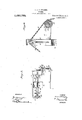
- FIG. 1 is a perspective view of a stocker constructed and arranged in accordance with the present. invention, shown in the receiving position and attached to the draper or delivery chute of a binder;
- Fig. 2 is a perspective view of the stooker, shown in stook, part ot' the receptacle being cut away to show the position .of the interior members thereof;
- Fig. 3 is a vertical longitudinal section of the same,
- Fig. l is a perspective view of the stooker, showing the parting. members ot' the stocker in partly separated relation;
- Fig. 5 is a detail view, on an enlarged scale, showing the operating gearing for iuaugurating the operation of the receptacle to deliver the stook;
- Fig. 6 is a detail view, in vertical section, showing a modified means for elevating the receptacle;
- Fig. 7 is a side elevation of a ⁇ s tooker constructed and arranged in accordance with the present invention, showing in dotted and full lines the arrangement of the receptacle in its receiving and dump ingl position, and the operating mechanism therefor.
- the receptacle illustrated in the acc0mpanying drawings consists of two sections formed as a frustum of' a cone and open Specification of Letters Patent.
- the conical shape is also preferably elliptical in cross section, as shown particularly in Fig. l of the drawings.
- the receptacle is formed ot' a solid rear sectionlO,
- the body section 1,12, 12 is, parted at the ⁇ center and rigidly secured to a square tubular frame 13.
- the tubular frame 13 and the sections 12, 12 and 10 are held rigidly in shape by annular flanges 111-, 14.
- the receptacle is pivotally mounted von a port# able platform 15, being supported thereon by standards 16, 1G, between the bifurcated upper ends whereof are pivoted supporting arms 1T, 17.
- the arms 17, 17 are united to the standards 1G, 16 by p.iv0ts'18,r18.v
- the arms 1T, 17 are providedivith extensions 19, 19, a rod .20 being connected to one of said extensions.
- the rod 2O is guided to impinge upon a hinged leaf ⁇ .21 forming part ot' an apron 22, which is supported on a stanchion rod 23 and suitably connected to the delivery chute A of the binder to which the stocker is connected.
- the connection thus formedl between the leaf 21 of the apron 22 and the receptacle provides for the shifting of the said leaf to 'arrest the delivery of the sheaves to the said receptacle when the said receptacle is upturncdin stook setting or deliveringposition.
- the platform 15. issupportcd on the binder by a hanger bar '24.
- Guiding wheels 25 and 2G are mounted in suitable bracket members QT and 2S respectively.
- the said bracket members are vertically adjustable, the bracket 27 being suspended on a screw threaded bolt Q9 and the bracket 28 being held by bolts 30, 30.
- the wheel 26 is mounted in fork arms 31, pivoted on a bolt 32 which is extended through the upper and vlower extensions of thc bracket ⁇ Q8 to form a Patented Feb. 1S, 1913..
- Ther stocker is further provided with a raised arch formed by a heavy metal strap 34, which is tixedly connected W1th the platform 15, and upon which slides the bracket' 27 when the screw 29 is manipulated in a threaded socket35 which is fixedly connected on the strap 34.
- the strap 34 ⁇ is secured at any 'convenient positionv to the binder structure, that shown inthe drawings being tothe geargshaft thereof.
- The-arched strap 34 is parted near the medianA section of the arch -to'fo-rm afraised mast, a narrow loopedrod 38 is provided at the end adjacent to4 the binder with a lever 39, the crook ofthe y said lever being' disposed adjacentfto the ,foot of the driver or attendant for the binder.
- the manipulation of the rod 38 effects the upturning' of the receptacle to a ⁇ receiving position,V such as shown in Fig. Lsof the drawings, after the delivery from the receptacle of the completed stook.-n
- This operation is produced by'a chain 40, which is supported upon a pulley 41 pivotally mounted in .the crank extension 37 and at the outer end thereof.
- the chain 40 is secured to the lower flange 14 on the forward and upper framing ⁇ section 12 of .the stoo-ker receptacle.
- the opposite end of the chain 40 is anchored to the upper flange 14 of the section 10, and .is roven through a pulley block
- the pulley block 44 is pivotally connected to a spiral springv43, which is anchored vto the ⁇ lower flange 14 of the section 10.
- the section 10 is provided near the upper edge thereofwith a pulley 42 to operate as a Iguide fender for the chain 40 when the same is disposed in the position where it would otherwise ride upon' the Hanege- 14 at the top ofthe said section.
- guide pulley 45 is formed on the upper edge of the section 12. The pulleys 42 and 45 are brought'.y into Aaction when the receptacle is disposed in the position illustrated infFig.
- the sheaves from which the stocks are formed are delivered over an apron or delivery chute formed on the attendant binder to the apron 22.
- The-apron' 22 is provided A similar i with a series of Wedge shaped upwardly inclined edge pieces 48, 48, and lspivotally connected at 49; 49 to the leaf 21T.
- Susthe strap 34 by means of dependedu clips 50 ing and advancing' the sheaves or bundles ⁇ by receptacle formed by the sections 10 and-12.
- the feeder mechanism comprises the endof a frame ⁇ 53 upon sprocket Wheels 54, 54.
- the feeding mechanism is rotatively connected With al kicker shaft56, at the end of which is provided a special sprocket Wheel 57.
- The'sprocket wheel 57 is rotatively cona sprocket wheel 59 on a shaft' 60.
- Fixedly connectedwith the shaftv 60 and the sprocket wheel 59 is a sprocket gear 61.
- the sprocket with the chains 58 and 62 constitute a transing mechanism fro-m the binder to which it is for the momentconnected.
- the spring ⁇ 51 when the weightr ofthe feeding' mechanism is imposed thereon, is extended to permit-the free end of the frame 53 tobe depressed 'upon the sheaves or bun dles, resting'A at the inner end of the said apron 22; .is elevated by reason of the uplifting of the leaf 2l.
- the leaf 21 is lifted by the rod 2O to the position shown in Fig. 2 ofthe drawin'gs. In the indicated position of the leaf 21, as shown in said Fia'.
- the feedingmechanism is raised lout of engagement With'the sheaves on the apron 22, and, further, the upturning of lthe leaf 21 prevents the delivery .of sheaves tothe receptacle formed by the sections 10 and 12 while the same' are in delivery position.
- the upward projection of the rod 20 is caused by the uplift of the extension 19,01? the arm 17l to which thesaid rod is attached.
- the arms 17 are disposed in the horizontal 'position shown in ⁇ Fig'. 2 of the drawings when the stooker receptacle is disposed in
- the members of the fra-ine 53 vare spaced. apart to dispose the belts 52, 52 at a desireddistance v"each from the other.
- ' 52 are provided at suitable intervals 'with a' gers 55, 55, when the-end of the frame sus? nected by 'means of'a sprocketchain 58 withV 4mission mechanism for operating the feed-VA p'ended above the stooker and SUPDOrted by u and a spiralspring 51, is a vfeeder for engag'- the apron 22 to deposit-the lsaine within the l less belts 52,r which are mounted at the end of the'ngers 55 with the said l,sheaves causes 10o gear 61 is rotatively connected with the sprocket wheel 106 bymeans of a sprocket' chain 62.
- the Wheels57,'59,.and 61,1;ogether From this position the frame 53 the position shown in said Fig. 2, which position is that assumed by the stocker when depositing the stool; upon the ground.
- the receptacle is supported in the receiving position shown in Fig. 1 of the drawings by the arms 1T, 17, which, in the receiving position of the receptacle are thrown lslightly to the rear ot' the vertical line of A suitably nieshe the pivots 1S, 18, and are there held by reason of the rod 2O striking upon the side ofthe standard 16.
- the receptacle is fur ther held in the receiving position by a latch bolt 63, which is engaged with and held by the threads of a worm 61, as seen more particularly in Fig. of the drawings.
- the bolt 63 is slidably mounted in a casing G5, which is bolted at 66 to the flange 14 secured to the section 12 of the receptacle as best seen in F ig. 5. 'When the receptacle is disposed in position, as shown in Fig. 1 of the drawings, the sleeve 67 is passed over the worm 641, and the bolty 63 is engaged with the threads of the said worm.
- the face of the bolt G3 is beveled to override the conical head 68 of the worm 64, and the successive convolutions of the thread thereof cause the bolt 63 to yield inwardly within saidcasing 65, ycompressing t-he spring 69 mounted in the said casing 65.
- the bolt 63 yields to the pressure exerted by the thread of the worm when being pressed thereover, and prevents tlieidisengagemcnt therewith when moved. outwardly along the said worm.
- the end of the bolt 63 is tapered to an angle which passes the head GS and threads of the worm when the force of the blow is sufficient to drive the bolt downward.
- the worin 64 Fixedly mounted upon the shaft TO is the sprocket wheel 106 carrying ,the chain 62 and at the oplosite end is a, pinion 71l t with a gear wheel 72, which is mounted upon a shattTB, upon the outer end whereof is termed the worin 64.
- the ratio between the gears T1 and T2 is related to produce a given number of revolutions ot the worm 64 for a given number ot revolutions of the shaft 70, and sprocketwheel 106 mounted on the said shaft 70 is connected bythe chain 62 and proportioned to the sprocket 61 to produce a certain rate of revolution of the worm 64 for each of the revolutions of the sprocket gear 61:
- the result of the above arrangement is that with one revolution of the sprocket gear 61, a certain distance ot' t-he belt 52 is traveled with the further result that the worm 64 receives a partial turn for each sheaf delivered in the stocker receptacle, and on a set number ot sheaves being deposited the bolt 63 is forced out ot' engagement with the worm 64.
- 'Ihe ratio between the gears 71 and ,72 is related to produce a given number of revolutions of the lworm 64 for a given number ot
- the sprocket wheel 106 mounted on the said shaft is related to the belts 52, 52 to produce a certain travel of the said belts for each of the revolutions of the sprocket gear 61.
- the result of the above arrangement is that with one revolution of the sprocket 106 a certain 'distance of the belts 52 is traveled, with the result thatta certain number of sheaves or bundles are acted upon by the said belts for delivery to the stocker receptacle.
- the stocker as above stated, is composed ot' the sections 10 and 12, which sect-ions' are hinged at 11, 11, and are formed to the shape of the frustum of a cone. In the receiving position ofthe stocker receptacle,
- the smaller end of the frustum is turned toward the rear of the platform 15.
- Theplatform 15 is cut away to provide a space forthe extension therethrough of the larger end of the frustuxn, and the contents, or stock, formed within the stocker or receptacle when the same is upturned, as shown in
- the platform and supporting frame of the stooker are connected with the binder to travel over the ground t-herewit.h',it becomes necessary, in order that the stobk may be left standmg, to remove the section 10, which, in the u standing position is to the rear of the stoo r.
- the springs t3 and 117 are provided for this purpose.
- the sections 1 0 and 12 are locked together at the lower edge by means of a strap hook .7 4 in a plate 75, as most clearly seen in Fig. 4 oit the drawings.
- the plate 75 is provided with a 'slot- 76, through which is extended the head of the hook 74.-
- the plate 7'5 is guided in a vloop 7 7 and is depressed by a spring 76 when the head of the hook 74 is driven through the slot 76. In this position thesections 1Q and 12 are locked together.
- the arm 81y is held in its normal position by ayspring 81, which isv wound on the spindle 7 9, and so disposed as to hold ⁇ the said arm in position to strike the plate 80 and .lift the plate 75, when the stook'er is rocked to deliver.
- the spring 8la yields to permit the arm 81 to pass over the plate 80.
- the upper edge of the plate 8O is inclined, as shown, to form a releasing point'at the forward edge of said plate which releases the latch 74.
- the lplate 7 5 is lowered on said upper' edge of the plate 80 in position to engage the said latch.
- the said'strap 82 is Y normally held by the spring 84 connected therewith in the path of the parting flange 85 of the section 10. ⁇ When the section 10 is lowered from the position shown .in Fig. 3 of the drawings to close upon the section 12, the ange 85 impinges upon the extended end of the strap 82 and forces the saine backward and out of engagement with thel drawings, the ⁇ lever 39 is manipulatedto.
- l To suspend the sheaves constituting the stook in the receptacle formed by the secuptiltin of the stooker, l have provided a' series o parallel rods 86, 86, which rods are rigidly and ixedly connected to the section 12.
- the said rods 86, 86 are of any convenient shape in' cross section, that shown in the drawings and preferred by me being triangular-in cross section, and' the wedge ed e thereof being toward the stock.
- the ro s 86, 86 are disposed in suiciently close Vtions 10 and 12 duringthe revolution or relation to preventthe sliding of thesheaves' 4for bundles out'from theenlarged'end .of the stooker when the same is"upturnedy to the position shown in Figs. 2 and 4. It is de'- sired that for the properformation ot a stock the base of the sheaves or bundles shall be outspread laterally, while the head or top of the sheaves is inclined centrally. This is accom lished' by providing; ⁇ 'a Series oi? spree.y ing rodsn87, 87,' ,which are piizotally i at - 93.
- the shaft 88 is formed'preferably of a tub or pipe section, through which a tie rod 9i is extended, the said rod v91 also passing through a center bar 92 and a standard tion the shaft 88 may be removed from the receptacle for repair or replacement.
- the rods 87, 87 are spread in a manner .o dispose the ends in an oval or elliptical arrangement.
- the shaft 95 is normally dispose il, as'seen in Fig. 1 of the drawings, with the lisk 94 arranged to hold the rods 87 in ext@ nded position. In this position the shaft is normally held by a spring 96, the lower 4end whereof is connected to the flange 14 of the section 12,.
- the sheaves or bundles are first delivered through the space 46 inthe frame 18 adjacent to the leaf 21 of the apron 22. posited in the receptacle through the irst of the said spaces 46 they are disposed with reference to the outspread arrangement of the rods 87 and packed to the form of the sections 10 and-12.
- a plate 98 is provided.
- the plate 98 is secured ixedly upon the platform 15, and is pro- As the sheaves are de' lformed in the center of the stook.
- the rods .100, 100 are hinged in loops 101, 101 formed on the side of the section 12 of the stooker.
- the rods 100, 100 are joined by a cross section 102, compelling the simultaneous movement of the said rods.
- One of the said rods is connected to the chain 40 by a chain section 108.
- the chain section 103 is of such length that when the stocker is in the horizontal position the rods 100, 100 are suspended on the section 103. Vhen, however, the stocker is tilted to the delivery position the chain 40 is drawn to the side of the section 12 and forces the rods 100, 100 in closed position across the spaces 46, 46.
- the sprocket wheels 54, 54 are mounted .upon the sleeve shaft 105, interposed f be.- .tween and fiXedly connected with the said sprocket wheels.
- the sleeve 105 isrevolubley on the shaftv 70, hence the shaft may ro tate, being compelled thereto by the Ichain 62 connecting the sprocket wheels V61 and 106, the latter being xedly mounted on the shaft 70.
- the hub of one ofthe sprocket wheels 54 and 4the hub of the sprocket wheel ,106 are provided with clutch teeth, adapted to engage when the two sprocket wheels are moved toward each other.
- a device in the shape of a pin 110 is employed vto vary the extent of the engagement of the holt 63 with the worm 64.
- Thepin 110 is seated in arecess formed in the face of the gear wheel. 72.
- the pin 110- is disposed in the path of the sleeve 67 and is adapted to regulate the approximation of the sleeve 67 lto the gear'7 2.
- the extension of the sleeve 67 over the worm 64 is varied.
- Fig. 6 ofthe drawings is shown avmodiyied form of the gearing for raising the stook'er to the horizontal or receiving position as shown'in Fig. 1l.
- the modification consists in the employment of a sprocket wheel 111 fiXedly connected with aspring vcasing 112, wherein is mounted a spring 113.
- the spring 113 is iixedly connected to a sta-y tionary shaft 114.
- the stationary shaft 114, and-spring and casing carried thereby, are supported at the ends of bracket arms 115.
- the springll' is suiicient-ly strong to lift the ⁇ forward extension of the chain 4 0 and the empty stocker from the platform 15 whent-he load has been delivered therefrom, but is not .suiiciently strong. to stand the weight of theloaded'stooker.
- a stocker comprising afrusto-conical shaped open-ended receptaclehaving two hinged half sections, one of said sections bcing rearwardly disposed when in .delivery position and the other of said sections having an openl receiving space in the median portion thereof; a feeding mechanism arranged to deliver sheaves within said recep-vl tacle; i 4spacing member disposed in said rcceptacle to spread the 'butt ends of said sheaves in saidkreceptacle; supporting'arms for said receptacle pivotally mounted to one side of the center of gravity of said receptacle when the same is in receiving position; a worm mounted on the supporting frame of said stocker; a timed transmission gear operatively connecting said feeding mechanism and said worm; a sleeve mounted onfsaid receptacle to Vguide the said worm; a yielding bolt carried by said sleeve to engage the convolutions of said worm, said' bolt being arranged to be moved
- a stocker comprising a frusto-conical shaped open-ended receptacle having two hinged half sections, one of said sections being rearwardly disposed when in delivery position and the other of said'sections having an open receiving space in the median portion thereof; afeeding mechanism -arranged to deliver sheaves within said receptacle; a spacing member disposed in said receptacle to spread the butt ends of said sheaves in said receptacle; supporting arms for said receptacle pivotally mountei toone side of the center of gravity of sai ,receptacle when the same is in receiving position; a,- loclting mechanism for maintaining said ,receptacle ind-receivingy position; means for releasing said locking mechanism; a plu- Vrality of springs arranged to lift the said rearwardly dispts'ed vsection on the connecting hinges thereof; a flexible lifting'memberconnected with said springs to support said rearwardly disposed section; and a'dev
- LFA stooker comprising a frusto-conical shaped open-ended receptacle having two hinged half sect-ions, one of said sectionsI being rearwardly disposed when in delivery position and the other of said sections havmg an open receiving space in the median portion thereof; a feeding mechanism arranged to deliversh'eaves within said recapta/cle;I a spacing member disposed in said receptacle to spread the butt ends of said sheavesV iny said receptacle; supporting arms for said receptacle pivotally mounted to one side of the center of gravity of said recep tacle when the same .is in receiving position; a locking mechanism for maintaining the said receptacle in receiving position, said locking mechanism being releasable by and 1n timedrelation with said feeding mechamsm; a plurality of springs' arranged to lift the said rearwardly disposed section on the Y.Conniacting hinges thereof; a flexible lifting member connected with said springs to support said rear
- a device connected' with said flexible lifting member for slacking thesame to permit the said rearwardly, disposed section 'to drop to a vertical position; and ai manually operatedlever. disposcd in operative position upon the connected binder and provided with a rod uniting said lever and said extension device.
- a stocker comprising a frusto-conical shaped open-ended receptacle having two' hinged half sections, one of said sections being rearwardly disposed when in delivery osition and the other of said sections havmg an open receiving space in the median portion thereof; a feeding mechanism arranged to deliver sheaves within said receptacle; a spacing memberI disposed in said receptacle to spread the but-t ends of said sheavesin said receptacle; supporting arms for said receptacle pivotally mounted to one Side of the ⁇ center of gravit-y 'of said receptacle when the same is in receiving posh tion; a locking mechanism for maintaining 'ally operated lever disposed in opera- 'sertion of said receptacle above the top of member for slacking the same'to permit the said rearwardly disposed section to drop to a vertical position; and ai manutiveposition uponthe connected binder and provided with a rod uniting said lever andA said extension device.
- a stooker comprising a frusto-conicalA shaped open-ended receptacle having two hinged half: sections, one of said sections bein-g rearwardly disposed when in delivery p'osition and the other of said sections having an open receiving space in the median portion thereof; a feeding mechanism arranged to deliver sheaves within-said' receptacle; a spaced member disposed in sazd receptacle to spread the butt ends of sail sheaves in said receptacle; supporting arms for said receptacle pivotally'mount-ed to (me side of. the center of gravity of said.
- a stocker comprising a rusto-conieal' shaped forming receptacle; a parting frame mounted on said receptacle and having al series ofpivotally mounted spreading members connected therewith; a disk rotativelymounted on said frame and disposed be-A tween said spreading members; and means mounted onNthe carrying frame of said.
Landscapes
- Life Sciences & Earth Sciences (AREA)
- Environmental Sciences (AREA)
- Preliminary Treatment Of Fibers (AREA)
Description
V. J. A. STOAKES.
sTooKBR.
APPLICATION FILED SEPT.15, 1910. 1 ,053,750, Patented Feb. 18, 1913.
' v 5 SHEETS-SHEET l.
uw j al IIE IIIIIIIHI [liu ...-AAA.
INVENTUH jawn/7%. @wbr/Mamie.;
A TTHNE Y 8 v. J. A. sToA-KES.
sTooKBR. APPLICATION FILED SEPT. l5, 1910.
' Patented Feb. 18, 1913.
5 SHEETS-SHEET 2.
Wl T NE 88E 8:
AA TTOHNEYS V. J. A. STOAKES.
sTooK'BR.
APPLIUATION FILED SEPT. 15, 1910.
Patented Feb.l18, 1913 5 sHnETs-SHBBT s.
11 TTORIV E YS WIT/VESSES."
V. J. A. STOAKES.
STOOKER.
APPLIGATION FILED snPT.15, 1910.
1,053,750. Patented Feb. 18, 1913.
I 5 SHEETS-SHEET 4.
HIHIHHII V. J. A. STOAKES.
STOOKER. APPLIoATxoN PILBD sBPT.15, 1910.
Patented Feb. 18, 1913.
5 SHEETS-SHEET 5.
Arron/vers position to set the VICTOR J. A. STOAKES, OF MOOSE JAV, SASKATCHEWAN, CANADA.
STOOKER.
Application filed September To all/whom t may concern Be it known that I,'V1c'ron J. A. S'roAnns, a subjecty of the King of Great Britain, and
a residento-f Moose Jaw, in the Province of Saskatchewan and Dominion of Canada, have invented a new and Improved Stooker` of which the following is affull, clear, and
vexact' description.
mongth'e principal objects which the present invention has view are: to provide a receptacle to receive, shape and deposit sheaves or bundles of grain-bearing or other straw; to provide a mechanism for automatically controlling the' operation of the receiving and dumping receptacle in timed relation with the operation of a binder machine to which said stooker is connected andV whereby the same is operated; and to provide means for adjusting the operating mechanism of the stooker to `vary the timed relation to the operation of the binder.
`One embodiment of vthe present invention is disclosed in the structure illustrated in the accompanying drawings, in which like characters of reference denote corresponding parts in all the views, and in which- Figure 1 is a perspective view of a stocker constructed and arranged in accordance with the present. invention, shown in the receiving position and attached to the draper or delivery chute of a binder; Fig. 2 is a perspective view of the stooker, shown in stook, part ot' the receptacle being cut away to show the position .of the interior members thereof; Fig. 3 is a vertical longitudinal section of the same,
showing the receptacle Aparted and in posi-` tion to deliver the stoot; Fig. l is a perspective view of the stooker, showing the parting. members ot' the stocker in partly separated relation; Fig. 5 is a detail view, on an enlarged scale, showing the operating gearing for iuaugurating the operation of the receptacle to deliver the stook; Fig. 6 is a detail view, in vertical section, showing a modified means for elevating the receptacle; and Fig. 7 is a side elevation of a `s tooker constructed and arranged in accordance with the present invention, showing in dotted and full lines the arrangement of the receptacle in its receiving and dump ingl position, and the operating mechanism therefor.
The receptacle illustrated in the acc0mpanying drawings consists of two sections formed as a frustum of' a cone and open Specification of Letters Patent.
ended. The conical shape is also preferably elliptical in cross section, as shown particularly in Fig. l of the drawings. The receptacle is formed ot' a solid rear sectionlO,
which. in its operation forms a gate portion hinged at 11, 11 upon the body section 1Q, 12. The body section 1,12, 12 is, parted at the `center and rigidly secured to a square tubular frame 13. The tubular frame 13 and the sections 12, 12 and 10 are held rigidly in shape by annular flanges 111-, 14. The receptacle is pivotally mounted von a port# able platform 15, being supported thereon by standards 16, 1G, between the bifurcated upper ends whereof are pivoted supporting arms 1T, 17. The arms 17, 17 are united to the standards 1G, 16 by p.iv0ts'18,r18.v The arms 1T, 17 are providedivith extensions 19, 19, a rod .20 being connected to one of said extensions. The rod 2O is guided to impinge upon a hinged leaf` .21 forming part ot' an apron 22, which is supported on a stanchion rod 23 and suitably connected to the delivery chute A of the binder to which the stocker is connected. The connection thus formedl between the leaf 21 of the apron 22 and the receptacle, provides for the shifting of the said leaf to 'arrest the delivery of the sheaves to the said receptacle when the said receptacle is upturncdin stook setting or deliveringposition.
The platform 15. issupportcd on the binder by a hanger bar '24. Guiding wheels 25 and 2G are mounted in suitable bracket members QT and 2S respectively. The said bracket members are vertically adjustable, the bracket 27 being suspended on a screw threaded bolt Q9 and the bracket 28 being held by bolts 30, 30. The wheel 26 is mounted in fork arms 31, pivoted on a bolt 32 which is extended through the upper and vlower extensions of thc bracket` Q8 to form a Patented Feb. 1S, 1913..
15, 1910. serial No. 582,195.
Ther stocker is further provided with a raised arch formed by a heavy metal strap 34, which is tixedly connected W1th the platform 15, and upon which slides the bracket' 27 when the screw 29 is manipulated in a threaded socket35 which is fixedly connected on the strap 34. The strap 34\is secured at any 'convenient positionv to the binder structure, that shown inthe drawings being tothe geargshaft thereof. The-arched strap 34 is parted near the medianA section of the arch -to'fo-rm afraised mast, a narrow loopedrod 38 is provided at the end adjacent to4 the binder with a lever 39, the crook ofthe y said lever being' disposed adjacentfto the ,foot of the driver or attendant for the binder.
By the rotation of therod .38 the chain 40 is slacked allowing sectionI 10 of the stooker receptacle to drop after the delivery from the receptacle of the completed stock.
Also, the manipulation of the rod 38 effects the upturning' of the receptacle to a`receiving position,V such as shown in Fig. Lsof the drawings, after the delivery from the receptacle of the completed stook.-n This operation is produced by'a chain 40, which is supported upon a pulley 41 pivotally mounted in .the crank extension 37 and at the outer end thereof. The chain 40 is secured to the lower flange 14 on the forward and upper framing` section 12 of .the stoo-ker receptacle. The opposite end of the chain 40 is anchored to the upper flange 14 of the section 10, and .is roven through a pulley block The pulley block 44 is pivotally connected to a spiral springv43, which is anchored vto the `lower flange 14 of the section 10. The section 10 is provided near the upper edge thereofwith a pulley 42 to operate as a Iguide fender for the chain 40 when the same is disposed in the position where it would otherwise ride upon' the Hanege- 14 at the top ofthe said section. guide pulley 45 is formed on the upper edge of the section 12. The pulleys 42 and 45 are brought'.y into Aaction when the receptacle is disposed in the position illustrated infFig. l of the`drawing's, which, as stated, yis the receivingposition of the receptacle assumed thereby when the sheaves or bundles are being' delivered to the receptacle through the spaces 46, 4G formed in theirame 13. The spring 43 operates in conjunction With a spring 47 to swing the section 10 on the hinges 11, 11. r
- The sheaves from which the stocks are formed are delivered over an apron or delivery chute formed on the attendant binder to the apron 22. The-apron' 22 is provided A similar i with a series of Wedge shaped upwardly inclined edge pieces 48, 48, and lspivotally connected at 49; 49 to the leaf 21T. Susthe strap 34 by means of dependedu clips 50 ing and advancing' the sheaves or bundles` by receptacle formed by the sections 10 and-12.
.The feeder mechanism comprises the endof a frame`53 upon sprocket Wheels 54, 54.
.series of extended fingers 55, 55. The fin pended by. .the spring' 51 is permitted to descend,I engage the sheaves from above as they are, delivered upon the apron 122, the 'sa-id fingers 55 sinking/between the straws forming'the said. sheaves. This engagement the sheavesto'roll up the inclined yapron* 22 and over the leaf 21 thereof, until they drop successively into the first of the spaces 46, 46.
'The feeding mechanism is rotatively connected With al kicker shaft56, at the end of which is provided a special sprocket Wheel 57. The'sprocket wheel 57 is rotatively cona sprocket wheel 59 on a shaft' 60.' Fixedly connectedwith the shaftv 60 and the sprocket wheel 59 is a sprocket gear 61. The sprocket with the chains 58 and 62, constitute a transing mechanism fro-m the binder to which it is for the momentconnected. i
` The spring` 51, when the weightr ofthe feeding' mechanism is imposed thereon, is extended to permit-the free end of the frame 53 tobe depressed 'upon the sheaves or bun dles, resting'A at the inner end of the said apron 22; .is elevated by reason of the uplifting of the leaf 2l. The leaf 21 is lifted by the rod 2O to the position shown in Fig. 2 ofthe drawin'gs. In the indicated position of the leaf 21, as shown in said Fia'. 2 4of the drawings, the feedingmechanism is raised lout of engagement With'the sheaves on the apron 22, and, further, the upturning of lthe leaf 21 prevents the delivery .of sheaves tothe receptacle formed by the sections 10 and 12 while the same' are in delivery position. The upward projection of the rod 20 is caused by the uplift of the extension 19,01? the arm 17l to which thesaid rod is attached. The arms 17 are disposed in the horizontal 'position shown in` Fig'. 2 of the drawings when the stooker receptacle is disposed in The members: of the fra-ine 53 vare spaced. apart to dispose the belts 52, 52 at a desireddistance v"each from the other. The belts 5,2,
' 52 are provided at suitable intervals 'with a' gers 55, 55, when the-end of the frame sus? nected by 'means of'a sprocketchain 58 withV 4mission mechanism for operating the feed-VA p'ended above the stooker and SUPDOrted by u and a spiralspring 51, is a vfeeder for engag'- the apron 22 to deposit-the lsaine within the l less belts 52,r which are mounted at the end of the'ngers 55 with the said l,sheaves causes 10o gear 61 is rotatively connected with the sprocket wheel 106 bymeans of a sprocket' chain 62. The Wheels57,'59,.and 61,1;ogether From this position the frame 53 the position shown in said Fig. 2, which position is that assumed by the stocker when depositing the stool; upon the ground.
The receptacle is supported in the receiving position shown in Fig. 1 of the drawings by the arms 1T, 17, which, in the receiving position of the receptacle are thrown lslightly to the rear ot' the vertical line of A suitably nieshe the pivots 1S, 18, and are there held by reason of the rod 2O striking upon the side ofthe standard 16. The receptacle is fur ther held in the receiving position by a latch bolt 63, which is engaged with and held by the threads of a worm 61, as seen more particularly in Fig. of the drawings. The bolt 63 is slidably mounted in a casing G5, which is bolted at 66 to the flange 14 secured to the section 12 of the receptacle as best seen in F ig. 5. 'When the receptacle is disposed in position, as shown in Fig. 1 of the drawings, the sleeve 67 is passed over the worm 641, and the bolty 63 is engaged with the threads of the said worm. The face of the bolt G3 is beveled to override the conical head 68 of the worm 64, and the successive convolutions of the thread thereof cause the bolt 63 to yield inwardly within saidcasing 65, ycompressing t-he spring 69 mounted in the said casing 65. The bolt 63 yields to the pressure exerted by the thread of the worm when being pressed thereover, and prevents tlieidisengagemcnt therewith when moved. outwardly along the said worm. The end of the bolt 63 is tapered to an angle which passes the head GS and threads of the worm when the force of the blow is sufficient to drive the bolt downward.
. Fixedly mounted upon the shaft TO is the sprocket wheel 106 carrying ,the chain 62 and at the oplosite end is a, pinion 71l t with a gear wheel 72, which is mounted upon a shattTB, upon the outer end whereof is termed the worin 64. The ratio between the gears T1 and T2 is related to produce a given number of revolutions ot the worm 64 for a given number ot revolutions of the shaft 70, and sprocketwheel 106 mounted on the said shaft 70 is connected bythe chain 62 and proportioned to the sprocket 61 to produce a certain rate of revolution of the worm 64 for each of the revolutions of the sprocket gear 61: The result of the above arrangement is that with one revolution of the sprocket gear 61, a certain distance ot' t-he belt 52 is traveled with the further result that the worm 64 receives a partial turn for each sheaf delivered in the stocker receptacle, and on a set number ot sheaves being deposited the bolt 63 is forced out ot' engagement with the worm 64. 'Ihe ratio between the gears 71 and ,72 is related to produce a given number of revolutions of the lworm 64 for a given number ot revolutions of the shaft vFig.' 2 of the drawings.
70, and the sprocket wheel 106 mounted on the said shaft is related to the belts 52, 52 to produce a certain travel of the said belts for each of the revolutions of the sprocket gear 61. The result of the above arrangement is that with one revolution of the sprocket 106 a certain 'distance of the belts 52 is traveled, with the result thatta certain number of sheaves or bundles are acted upon by the said belts for delivery to the stocker receptacle.
In the above manner there is provided'a mechanism, the operation whereof gradually forces outward the bolt 63 and the upper edge of the section 12 of the receptacle. When the bolt 63 is finally moved forward by the worm 64 to be released thereby, the stocker receptacle has been rocked forward on the arms 11,17 past the pivotal bearings of the said arms 17 and will then moveto discharging position by gravity. When now the feeding mechanism by which the sheaves are delivered to the stocker, thus arresting the delivery of the sheaves until the stooker is again disposed in the position shown in Fig. 1.
The stocker, as above stated, is composed ot' the sections 10 and 12, which sect-ions' are hinged at 11, 11, and are formed to the shape of the frustum of a cone. In the receiving position ofthe stocker receptacle,
such as shown in Fig. l of the drawings, the smaller end of the frustum is turned toward the rear of the platform 15. Theplatform 15 is cut away to provide a space forthe extension therethrough of the larger end of the frustuxn, and the contents, or stock, formed within the stocker or receptacle when the same is upturned, as shown in As the platform and supporting frame of the stooker are connected with the binder to travel over the ground t-herewit.h',it becomes necessary, in order that the stobk may be left standmg, to remove the section 10, which, in the u standing position is to the rear of the stoo r. For this purpose are provided the springs t3 and 117;
Tt. will be noted that in the uptilt ofy the stook the chain 40 runs over the pulley 41, but does 'not relieve the strain upon the spring 43. Further, it will be noted that in the uptilted position of the stocker, as shown in Figs. 2 and 4 of the drawings, the spring 43 is extended outward from the section -10 so as to exert an outward pulling strain upon the section 10 at the lower edge rates the sections and 12 at the lower edge when the lock by which the two sections are joined is released.
The sections 1 0 and 12 are locked together at the lower edge by means of a strap hook .7 4 in a plate 75, as most clearly seen in Fig. 4 oit the drawings. The plate 75 is provided with a 'slot- 76, through which is extended the head of the hook 74.- The plate 7'5 is guided in a vloop 7 7 and is depressed by a spring 76 when the head of the hook 74 is driven through the slot 76. In this position thesections 1Q and 12 are locked together.
When inthe course of voperation the stocker is uptilted as shown in Fig. 4 of the drawings, a cam plate 80 mounted on the side of the platform 15 is impinged. upon by an arm 8l which lifts the .plate 75 out of :engagement with` the hook 74. The hook 74 being thus released the spring 43 -is given the needed opportunity to separate the lower edges oit'. thesections 10 and 12, asshown in the said Fig. 4. Should the strain of the spring 43 be insutlicient to separate the sec` tions 10 and 12, this'will be accomplished by the rather sudden arresting of the section 12 when thesame strikesupon the platform`15. The arm 81y is held in its normal position by ayspring 81, which isv wound on the spindle 7 9, and so disposed as to hold `the said arm in position to strike the plate 80 and .lift the plate 75, when the stook'er is rocked to deliver. When, however, the stooker is raised to the horizontaler receiving position, the spring 8la yields to permit the arm 81 to pass over the plate 80. The upper edge of the plate 8O is inclined, as shown, to form a releasing point'at the forward edge of said plate which releases the latch 74. At the rear of said plate 80 the lplate 7 5 is lowered on said upper' edge of the plate 80 in position to engage the said latch. Coincident with the parting of the sections 10 and 12 at the lower edges thereof, the upper edges are lifted out of alinement so that the pull ot the spring 47 is permitted to be exerted to draw the-edges of the sections to which the said spring is connected toward each other, andv to rotate the said sections on the hinges 11, 11. From this point. the operations o'f the two springs 43 and 47 are in unison, and result in the uplifting `of the section 10 to the posit-ion shown in Fig. 3 of the drawings. `In this position the section 10 is lifted .above-the top or head of the' vstook whicli'has been strap 82 is slidably mounted uponthe seetion 12, and is maintained in advanced position by a spring 84 mounted on the said section. The strap 82 is projected through the parting flange of thesection 12 and is eX- tended into thepath of the parting flange 8 5 otthesection 10.
The said'strap 82 is Y normally held by the spring 84 connected therewith in the path of the parting flange 85 of the section 10. `When the section 10 is lowered from the position shown .in Fig. 3 of the drawings to close upon the section 12, the ange 85 impinges upon the extended end of the strap 82 and forces the saine backward and out of engagement with thel drawings, the` lever 39 is manipulatedto.
rotate the rod 88 and the crank extension 37 thereof to lower the pulley 41 and the chain `4() connected therewith. This operation` slackens the chain 40 and removes the strain from the spring 43 and lessens thev pull on the out-er extended-iyl edge .of the section A10; Thespring 47 being insufficient to support the section 10 iii the raised position, the said section. drops to the closing position above described. Vhen the sections 10 and 12 are' reunited by the section 10 being dropped upon the section 12, as stated, the lever 39 is again manipulated to return the crank extension 37 and the pulley 41 carried thereon to the upraised position shown in Fig. 1.
This action reestablishes the pull on thev chain 40 and on the spring 43 connectedv` therewith.
To suspend the sheaves constituting the stook in the receptacle formed by the secuptiltin of the stooker, l have provided a' series o parallel rods 86, 86, which rods are rigidly and ixedly connected to the section 12. The said rods 86, 86 are of any convenient shape in' cross section, that shown in the drawings and preferred by me being triangular-in cross section, and' the wedge ed e thereof being toward the stock. The ro s 86, 86 are disposed in suiciently close Vtions 10 and 12 duringthe revolution or relation to preventthe sliding of thesheaves' 4for bundles out'from theenlarged'end .of the stooker when the same is"upturnedy to the position shown in Figs. 2 and 4. It is de'- sired that for the properformation ot a stock the base of the sheaves or bundles shall be outspread laterally, while the head or top of the sheaves is inclined centrally. This is accom lished' by providing;` 'a Series oi? spree.y ing rodsn87, 87,' ,which are piizotally i at - 93. By reason of this manner of eonstrucmounted upon a shaft 88, eyeleted ends being formed on the said rods for that purpose. The outer ends of the rods are connected by short chain sections 89, 89 to prevent the overspreading of the outer ends of the said rods. 'In the disposition of the rods upon the shaft 88 they are supported by sleeves 90, 90. The shaft 88 is formed'preferably of a tub or pipe section, through which a tie rod 9i is extended, the said rod v91 also passing through a center bar 92 and a standard tion the shaft 88 may be removed from the receptacle for repair or replacement.
The rods 87, 87 are spread in a manner .o dispose the ends in an oval or elliptical arrangement. For this purpose a disk 94 is einployed, which disk is fixedly mounted on a =haft 95, and-is provided with a shape substantially that which it is desired the rod 87, 87 shall assume when the said rods are outspread. The shaft 95 is normally dispose il, as'seen in Fig. 1 of the drawings, with the lisk 94 arranged to hold the rods 87 in ext@ nded position. In this position the shaft is normally held by a spring 96, the lower 4end whereof is connected to the flange 14 of the section 12,. YThe upper end of the sj ring is connected to a crank handle 97 disposed in lateral extension upon the shaft 95. 'l he portion of the spring 96 draws the crank f7 to a line with the bar'92, separating the " ods 87, 87.
In thel operation above s et forth of he feeding mechanism, which occurs when the receptacle formed by the sections 10 and 12 is in the horizontal position shown in Fig. 1 of the drawings, the sheaves or bundles are first delivered through the space 46 inthe frame 18 adjacent to the leaf 21 of the apron 22. posited in the receptacle through the irst of the said spaces 46 they are disposed with reference to the outspread arrangement of the rods 87 and packed to the form of the sections 10 and-12. Vhen, in due course, the section of the' receptacle juxtaposed to the apron 22 becomes illed, the operation of the feeding mechanism carries the succeeding bundles or sheaves across the now filled space, and delivers the same into the space 46 on -the far side of the center bar 92. The
o eration of filling the receptacle now contlnues until the far side of the said receptacle is filled. When this is accomplished by reason of the rotation of the worm 64. the bolt 63 is ejected from engagement with the said worm and the stooker is uptilted as described.
It becomes necessary to collapse the rods 87, 87 so that the spreading form may be Withdrawn from the surrounding sheaves or stook. It is for this purpose that a plate 98 is provided. The plate 98 is secured ixedly upon the platform 15, and is pro- As the sheaves are de' lformed in the center of the stook.
be drawn through the stook in the direction' in which the platform is carried by the binder to which it is attached. This is done when and as the section 10 is lifted to the raised position shown in Fig, 3 of the drawings. It will also be noted in said figure of the drawings that the disk 94 is disposed in the vertical arrangement just above described.
It is to prevent the outward falling of the n sheaves through the spaces 46, 46 that I have provided the rods 100, 100. The rods .100, 100 are hinged in loops 101, 101 formed on the side of the section 12 of the stooker. The rods 100, 100 are joined by a cross section 102, compelling the simultaneous movement of the said rods. One of the said rods is connected to the chain 40 by a chain section 108. The chain section 103 is of such length that when the stocker is in the horizontal position the rods 100, 100 are suspended on the section 103. Vhen, however, the stocker is tilted to the delivery position the chain 40 is drawn to the side of the section 12 and forces the rods 100, 100 in closed position across the spaces 46, 46. This action of the lrods 100, 100 occurs before the stooker is uptilted sutiicient to cause any of the sheaves to fall outward through the spaces the rods 87, 87 have' been outspread, the butts of the sheaves comprising the stook are 'extended outward and the Ventilating space is When the rods 87, 87 are colla sed the buttsof the sheaves are prevented rom contracting inward on .the stook format-ion, by the rods 86, 86. When the stook has been thus deposited, and the stocker moved so that the section 10 may be dropped into position to lock with the section 12 without interference with the stook, the operator of the binder depresses the lever 39 and rocks the rod 38 'is raised, the two sections' 10 and 12 are lifted bythe chain'40 vto the horizontal or 'I receiving position shown in Fig. 1 of 'the drawings; -It' will be noted, as best seenA inv Fig. 7, that the. stocker, when in-vert-ical position, is disposed substantially forward I ,i of the lpivots 18 on which the s'aid stooker 15 may be said to swing. 'Ihe pivot18 and the rear of the stooker are substantially in line ,with the pulley'41 when disposed in the y In this "position of the parts, it will.` be understood lthat the-lift of the section of the chain`40 raised position 'just referred to.
to which ,the spring 43 is connected is vsubstantially resisted by reason of the disposition of the samein substantial'lythe direct line of the pivot`l8 andthe pulley V41. This permits the'full eectiveness of the pull of.
the chain 40 and springs 43ai1d 96 to be eX- erted on the "section of the said chain, to
which is connected 'the spring 96. The immediate result of this arrangement is that the'A forwardvedge. of the stooker, the two sectionslO and 12 being locked, is lifted, the stocker swinging on the pivots 18 untfl the same is disposedin the` horizontal receiving position, wherein it is heldby the worm 64. The stooker being thus returned to its horizontal position the sleeve I67 is ex-v tended over the worm 64 until arrested by the gear wheel 72. The bolt 63 is held in enga glement with the worm 64.' Thestooker is now locked against disadjustmentin the horizontal orreceiving position.
The sprocket wheels 54, 54 are mounted .upon the sleeve shaft 105, interposed f be.- .tween and fiXedly connected with the said sprocket wheels. The sleeve 105 isrevolubley on the shaftv 70, hence the shaft may ro tate, being compelled thereto by the Ichain 62 connecting the sprocket wheels V61 and 106, the latter being xedly mounted on the shaft 70. The hub of one ofthe sprocket wheels 54 and 4the hub of the sprocket wheel ,106 are provided with clutch teeth, adapted to engage when the two sprocket wheels are moved toward each other. It will begunderstoo'd that the sprocket wheel 106 and shaft 70 connected therewith are driven constantly by' the driving mechanism of the binder to which the stocker is attached. I'nterposed between a framing arm 107, set down from the strap 34', vand the hub of the outer sprocket wheel 54, is'a spiral spring 108. The spring 108 tends normally to 4move the sprocketwheel 54 so that-the clutch hubs rof ',the said sprocket wheel 54v and ,the
sprocket wheel l106 are engaged. When the The section l10, when dropped lmembered, is when` the stocker is in the and to the frame 53 of the feeder mechanism. `When in the course lof operation the leaf the rod 109 crowds the frame laterally to move the sleeve 105 out of' engagement with the sprocket-wheel 106, as'shownvin Fig. 5
gaged from the sprocket wheel 106, the feedthrewithlare arrested.
' A device in the shape of a pin 110 is employed vto vary the extent of the engagement of the holt 63 with the worm 64. Thepin 110 is seated in arecess formed in the face of the gear wheel. 72. The pin 110-is disposed in the path of the sleeve 67 and is adapted to regulate the approximation of the sleeve 67 lto the gear'7 2. By varying the length of the pin 110. the extension of the sleeve 67 over the worm 64is varied.
' In Fig. 6 ofthe drawings is shown avmodiyied form of the gearing for raising the stook'er to the horizontal or receiving position as shown'in Fig. 1l. The modification consists in the employment of a sprocket wheel 111 fiXedly connected with aspring vcasing 112, wherein is mounteda spring 113. The spring 113 is iixedly connected to a sta-y tionary shaft 114. The stationary shaft 114, and-spring and casing carried thereby, are supported at the ends of bracket arms 115. The springll' is suiicient-ly strong to lift the `forward extension of the chain 4 0 and the empty stocker from the platform 15 whent-he load has been delivered therefrom, but is not .suiiciently strong. to stand the weight of theloaded'stooker. The operaT the spring 41 "13'is independent ofthe operation of the fcrank" extension 37. As inthe tension 37 is depressed to lower the section 10 of the stocker.` When thewheel 111 is provided the operation as above described is is .released from thehook 8.3 by vtheclosing of the section 10, the spring 113 immediately operatesto lift the stookerto the po sition shown in Fig.' 1, and that wit-hout waiting upon` the raising of the crank eX- tensi/ony 37. f, la
. Having thus' described my invention, what ters Patentv is iframe 53 is lowered, which, it will be re- 21 is raised, thereby lifting the frame 53,-
of the drawings.4 When. the sprocket wheels mounted on the sleeve 105 are thus disen-y ing mechanism and the chains 52 connectedl tion of the sprocket wheel 111; as driven by above described mechanism the crank ex slightly varied, in that when the strap 82 E lgAstooker, comprising-a frusto-conical horizontal orY receiving position, the rod 109 assumes more nearly vertical position, per- The. arm 109 is connected to the strap 34 I claim asl new and desire to secure by Letsaid rearwardly disposed section of said shaped open-ended receptacle having two hinged half sections, one of said sections heing rearwardly disposed when in delivery position and the other of said' sections hav-v ing an open receiving space in the median portion thereof; a feeding mechanism ar ranged to deliversheaves within said receptacle; a spacing memberl disposed in sai'd receptacle to spread the butt` ends of said sheaves in said receptacle; supporting arms for said receptacle, pivotally mounted to one side of the center of gravity of said receptacle when the same is in receiving position; a locking mechanism for maintaining said stooker in receiving position, said locking mechanism embodying a worin mounted on and rotated by Said feeding mechanism; a yielding bolt carried on said 'stocker to engage said worm when said stocker is raised to receiving position; and means to lift the stooker above lthe top of the stock.
2. A stocker, comprising afrusto-conical shaped open-ended receptaclehaving two hinged half sections, one of said sections bcing rearwardly disposed when in .delivery position and the other of said sections having an openl receiving space in the median portion thereof; a feeding mechanism arranged to deliver sheaves within said recep-vl tacle; i 4spacing member disposed in said rcceptacle to spread the 'butt ends of said sheaves in saidkreceptacle; supporting'arms for said receptacle pivotally mounted to one side of the center of gravity of said receptacle when the same is in receiving position; a worm mounted on the supporting frame of said stocker; a timed transmission gear operatively connecting said feeding mechanism and said worm; a sleeve mounted onfsaid receptacle to Vguide the said worm; a yielding bolt carried by said sleeve to engage the convolutions of said worm, said' bolt being arranged to be moved by the said worm to become disengaged therewith; and
means to lift the said rearwardly disposed section of said receptaclei above theitop of the stook. 1
3. A stocker, comprising a frusto-conical shaped open-ended receptacle having two hinged half sections, one of said sections being rearwardly disposed when in delivery position and the other of said'sections having an open receiving space in the median portion thereof; afeeding mechanism -arranged to deliver sheaves within said receptacle; a spacing member disposed in said receptacle to spread the butt ends of said sheaves in said receptacle; supporting arms for said receptacle pivotally mountei toone side of the center of gravity of sai ,receptacle when the same is in receiving position; a,- loclting mechanism for maintaining said ,receptacle ind-receivingy position; means for releasing said locking mechanism; a plu- Vrality of springs arranged to lift the said rearwardly dispts'ed vsection on the connecting hinges thereof; a flexible lifting'memberconnected with said springs to support said rearwardly disposed section; and a'device connected with said flexible lifting member for slacking the same to permit the said rearwardly'disposed section to drop to a vertical position. 4
LFA stooker, comprising a frusto-conical shaped open-ended receptacle having two hinged half sect-ions, one of said sectionsI being rearwardly disposed when in delivery position and the other of said sections havmg an open receiving space in the median portion thereof; a feeding mechanism arranged to deliversh'eaves within said recapta/cle;I a spacing member disposed in said receptacle to spread the butt ends of said sheavesV iny said receptacle; supporting arms for said receptacle pivotally mounted to one side of the center of gravity of said recep tacle when the same .is in receiving position; a locking mechanism for maintaining the said receptacle in receiving position, said locking mechanism being releasable by and 1n timedrelation with said feeding mechamsm; a plurality of springs' arranged to lift the said rearwardly disposed section on the Y.Conniacting hinges thereof; a flexible lifting member connected with said springs to support said rearwardly disposed section;
a device connected' with said flexible lifting member for slacking thesame to permit the said rearwardly, disposed section 'to drop to a vertical position; and ai manually operatedlever. disposcd in operative position upon the connected binder and provided with a rod uniting said lever and said extension device.
5. A stocker, comprising a frusto-conical shaped open-ended receptacle having two' hinged half sections, one of said sections being rearwardly disposed when in delivery osition and the other of said sections havmg an open receiving space in the median portion thereof; a feeding mechanism arranged to deliver sheaves within said receptacle; a spacing memberI disposed in said receptacle to spread the but-t ends of said sheavesin said receptacle; supporting arms for said receptacle pivotally mounted to one Side of the `center of gravit-y 'of said receptacle when the same is in receiving posh tion; a locking mechanism for maintaining 'ally operated lever disposed in opera- 'sertion of said receptacle above the top of member for slacking the same'to permit the said rearwardly disposed section to drop to a vertical position; and ai manutiveposition uponthe connected binder and provided with a rod uniting said lever andA said extension device.
6. A stooker, comprising a frusto-conicalA shaped open-ended receptacle having two hinged half: sections, one of said sections bein-g rearwardly disposed when in delivery p'osition and the other of said sections having an open receiving space in the median portion thereof; a feeding mechanism arranged to deliver sheaves within-said' receptacle; a spaced member disposed in sazd receptacle to spread the butt ends of sail sheaves in said receptacle; supporting arms for said receptacle pivotally'mount-ed to (me side of. the center of gravity of said. receptacle; a locking mechanism for maintain ing said receptacle in receiving position; means to lift the said rearwardly disposed the stoo-k; and means operatively connect` irg the said feeding mechanism and said supporting arms for said receptacle, for lifting the said feeding mechanism from envagement with the sheaves as and when the Said receptacle is rotated to the upturned position on said arms,
7. A stocker, comprising a rusto-conieal' shaped forming receptacle; a parting frame mounted on said receptacle and having al series ofpivotally mounted spreading members connected therewith; a disk rotativelymounted on said frame and disposed be-A tween said spreading members; and means mounted onNthe carrying frame of said.
lon said receptacle and having. a series of pivotally mounted spreading members connected therewith; a disk rotatively mounted lon said frame and disposed between 'said spreading members; means mounted on the carrying frame of sald stooker for rotating said disk when the said receptacle is lrocked' to delivery posit-ion; and a plurality of parq allel bars tixedly connected to the section of y said receptacle to which said,rearwardly opening section is hinged, said bars arranged to prevent the exit therethroughof the sheaves when received in said receptacle.
In testimony whereof I have signedvthis specification in the presence of two subscribing Witnesses.
v Vieron J. A. s'froAKEs.
Witnesses f VIOLET STEWART, JOSEPH MoKINNoN.
Cdpies of this patent may be obtained for* ve cents each, by addressing the Commissioner of Patents,4
Washngton, D. C.
Priority Applications (1)
| Application Number | Priority Date | Filing Date | Title |
|---|---|---|---|
| US58219510A US1053750A (en) | 1910-09-15 | 1910-09-15 | Stooker. |
Applications Claiming Priority (1)
| Application Number | Priority Date | Filing Date | Title |
|---|---|---|---|
| US58219510A US1053750A (en) | 1910-09-15 | 1910-09-15 | Stooker. |
Publications (1)
| Publication Number | Publication Date |
|---|---|
| US1053750A true US1053750A (en) | 1913-02-18 |
Family
ID=3122010
Family Applications (1)
| Application Number | Title | Priority Date | Filing Date |
|---|---|---|---|
| US58219510A Expired - Lifetime US1053750A (en) | 1910-09-15 | 1910-09-15 | Stooker. |
Country Status (1)
| Country | Link |
|---|---|
| US (1) | US1053750A (en) |
-
1910
- 1910-09-15 US US58219510A patent/US1053750A/en not_active Expired - Lifetime
Similar Documents
| Publication | Publication Date | Title |
|---|---|---|
| US1300362A (en) | Beet-harvester. | |
| US1615716A (en) | Potato digger | |
| US277660A (en) | Corn-harvester | |
| US651279A (en) | Corn or cane harvesting machine. | |
| US532646A (en) | Corn-harvester | |
| US981319A (en) | Binder-reel. | |
| US660041A (en) | Shocking attachment for corn-harvesters. | |
| US530493A (en) | Corn-harvester | |
| US426475A (en) | spauldingl | |
| US1240955A (en) | Beet-harvester. | |
| US719482A (en) | Grain-thresher. | |
| US186168A (en) | Improvement in corn-harvesters | |
| US223213A (en) | Said knowlton | |
| US748556A (en) | Mowing-machine. | |
| US110138A (en) | Improvement in grain-binders | |
| US534526A (en) | Corn-harvester | |
| US350443A (en) | osg-ood | |
| US575871A (en) | boese | |
| US263715A (en) | Grain-binder | |
| US1263540A (en) | Grain-shocker. | |
| US1040007A (en) | Grain-shocking device. | |
| US559754A (en) | shively | |
| US736590A (en) | Corn-harvester. | |
| US99968A (en) | Improvement in grain harvesters and binders | |
| US720444A (en) | Corn-harvester. |