CROSS-REFERENCE TO RELATED APPLICATIONS
This application is the U.S. national phase entry under 35 U.S.C. § 371 of International Application No. PCT/US2016/012572, filed Jan. 8, 2016, entitled QUICK DISCONNECT ASSEMBLY AND METHOD OF USE, which in turn claims priority to and benefit of U.S. Provisional Application No. 62/101,161, filed Jan. 8, 2015, the contents of which are incorporated herein by reference in their entirety for all purposes.
FIELD OF THE INVENTION
The present disclosure relates to quick disconnect assemblies in general and, more particularly, to a quick disconnect housing and shaft assembly used in a surgical apparatus.
BACKGROUND
A surgical apparatus may contain a shaft inserted into a housing and secured in place in many ways, such as with a set screw, a locking shaft collar, or a cross-pin fitting into a groove. During a surgical operation, the shaft may need to be detached and removed from the housing, for example, with a surgical apparatus that has a reusable handle and a single-use front end. Therefore, it is desirable for the surgical apparatus to have a quick disconnect mechanism between the housing and shaft that is simple, cost-effective, reliable and easy to use.
SUMMARY
The disclosure described herein is a quick disconnect assembly including a generally tubular housing extending between distal and proximal ends, and a rotatable nut adapted to secure a threaded shaft. This mechanism can be applied to any surgical construct where a removable component is desired, particularly with reusable and disposable components. Advantageously, the quick disconnect assembly of this disclosure will accommodate a variety of shaft lengths and/or configurations. Furthermore, the quick disconnect assembly of this disclosure provides the ability to slide and lock with a separate axial movement. Both the shaft and the housing can easily be assembled and disassembled repeatedly. The housing and shaft can further be assembled and disassembled at adjustable positions. The adjustments to the positions can be of any granularity.
The quick disconnect assembly of this disclosure is furthermore advantageous over the prior art because current apparatuses require at least one additional mechanical element to lock the shaft to the nut. The present disclosure uses fewer parts, leading to simplicity, reduced costs, and ease of use for surgeons.
In an embodiment of the quick disconnect assembly of this disclosure, the quick disconnect assembly includes a tubular housing extending along a longitudinal axis between a proximal end and a distal end. The housing includes a cannulation extending between the proximal and distal ends. The cannulation includes a first portion extending from the housing proximal end and a second portion. The second portion is continuous with the first portion, extending from the housing distal end and having a diameter smaller than the first portion.
The housing further includes a cam pin secured to the housing and extending transverse to the longitudinal axis within the first portion. The housing also includes a nut positioned within the housing. The nut includes a first, threaded channel formed through a length of the nut and adapted to threadingly engage a threaded shaft, a second, non-threaded channel extending at a selected angle with respect to the first channel and intersecting the first channel, the second channel having a diameter greater than the threaded shaft, and an arcuate groove formed on an outer surface of the nut and extending between the proximal and distal ends of the nut. The first channel of the nut is oriented such that, when the cam pin engages the groove at about a distal end of the nut, the nut is positioned in a loading position where the second channel extends approximately parallel to the longitudinal axis of the housing. The second channel of the nut is oriented such that, when the cam pin engages the groove at about a proximal end of the nut, the nut is positioned in a locking position where the first channel extends approximately parallel to the longitudinal axis of the housing.
In further embodiments, the housing is tubular. The nut comprises a non-threaded channel. The quick disconnect assembly comprises a threaded shaft threadingly engaged with the first channel of the nut and a nut carrier axially coupled to the nut. Distal advancement of the threaded shaft while the nut is in the loading position engages a distal end of the threaded shaft with a nut carrier and distally advances the nut carrier and nut. The nut is urged from the loading position to the locking position by the distal advancement of the threaded shaft such that threads of the first channel threadingly engage the threads of the threaded shaft. Insertion of the threaded shaft into the nut is not inhibited by the second channel when the nut is in the loading position. The diameter of the second portion of the housing cannulation is selected to prevent distal movement of the nut when the nut is in the locking position. A diameter of the non-threaded channel of the nut is selected to allow passage of the threaded shaft. A clearance inside the housing is selected to allow the nut to rotate into the loading position but to restrict the nut from rotating into a position that would disengage the threaded shaft from the first channel of the nut.
In an embodiment of the method of connecting a housing and shaft of this disclosure, the method includes: engaging a cam pin secured to a housing with a distal end of a groove formed in the surface of a nut, the nut comprising a first channel in communication with a second channel extending at a selected angle with respect to the first channel and intersecting the first channel, wherein the nut is positioned within a cannulation of the housing such that the second channel of the nut extends approximately parallel to a longitudinal axis of the housing; inserting a threaded shaft into the first channel of the nut; and distally advancing the threaded shaft within the nut until a distal end of the threaded shaft engages with a nut carrier and distally advances the nut carrier and the nut within the cannulation of the housing. The distal advancement of the nut within the cannulation of the housing causes the cam pin to move from the distal end of the groove to the proximal end of the groove. When the cam pin engages the proximal end of the groove, the first channel of the nut extends approximately parallel to the longitudinal axis of the housing and the threaded shaft is lockingly engaged with the threaded channel of the nut. The cannulation of the housing comprises a first portion and a second portion, a diameter of the second portion being smaller than a diameter of the first portion. The diameter of the second portion of the housing cannulation is selected to prevent distal movement of the nut when the threaded shaft is lockingly engaged with the threaded channel of the nut.
BRIEF DESCRIPTION OF THE DRAWINGS
The foregoing will be apparent from the following more particular description of example embodiments of the disclosure, as illustrated in the accompanying drawings.
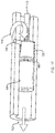
FIG. 1A is a diagram illustrating an example embodiment of the loading position of present disclosure;
FIGS. 1B-D illustrate details of the embodiment of FIG. 1A;
FIG. 1E is a diagram illustrating the transition from the loading to the locking position of the embodiment of FIG. 1A; and
FIG. 1F is a diagram illustrating the locking position of the embodiment of FIG. 1A.
DETAILED DESCRIPTION
Examples of the quick disconnect assembly of this disclosure will now be discussed with reference to the figures.
In the description that follows, like components have been given the same reference numerals, regardless of whether they are shown in different examples. To illustrate example(s) in a clear and concise manner, the drawings may not necessarily be to scale and certain features may be shown in somewhat schematic form. Features that are described and/or illustrated with respect to one example may be used in the same way or in a similar way in one or more other examples and/or in combination with or instead of the features of the other examples.
Comprise, include, and/or plural forms of each are open ended and include the listed parts and can include additional parts that are not listed. And/or is open ended and includes one or more of the listed parts and combinations of the listed parts.
FIGS. 1A-E illustrate an example embodiment of the quick disconnect assembly 100 of this disclosure and its method of use. The components of the quick disconnect assembly 100 may vary in size, shape or materials and are selected to be suitable to the surgical apparatus of their use.
In FIG. 1A, the quick disconnect assembly 100 generally includes a housing 102 (shown in cross-section), a nut carrier 104, a rotatable nut 108 and a threaded shaft 112. The nut carrier 104 includes a distally extending bed 105 on which the rotatable nut 108 rests. The housing 102 can be a tubular housing extending along a longitudinal axis between a proximal end and a distal end. However, a person of ordinary skill in the art can recognize that the housing 102 can be extrapolated as a housing of another shape in other embodiments. The housing 102 can include a cannulation 116 extending between the proximal and distal ends. The nut carrier 104 and the rotatable nut 108 are positioned within the cannulation 116, as described in more detail below. The nut carrier 104 includes an internal, non-threaded cannulation 124 extending from a proximal to a distal end. The shapes of both of the nut carrier 104 and the rotatable nut 108 can be tubular, but are selected to match the inside shape of the cannulation 116. The threaded shaft 112 may be disposable. The rotatable nut 108 includes a first channel 118 and a second channel 120, described in more detail below.
As shown in FIG. 1B, the cannulation 116 can include a first portion 116 a and a second portion 116 b. The first portion 116 a extends from the proximal end of the housing 102. The second portion 116 b is continuous with the first portion 116 a and extends from the distal end of the housing 102. The second portion 116 b has a diameter smaller than a diameter of the first portion 116 a, the diameter being selected to prevent distal movement of the rotatable nut 108. The housing 102 can also include a cam pin 106 secured to the housing 102 and extending traverse to the longitudinal axis within the first portion 116 a. The function of the cam pin 106 will be described further below. The nut 108 (FIG. 1A) is disposed within the first portion 116 a. The nut carrier 104 (FIG. 1A) is primarily disposed within the second portion 116 b but may extend into the first portion 116 a.
As shown in FIG. 1C, the rotatable nut 108 includes a first, threaded channel 118 formed through a length of the rotatable nut 108 and adapted to threadingly engage the shaft 112. The rotatable nut 108 includes a second, non-threaded channel 120 extending at a selected angle with respect to the first channel 118 and intersecting the first channel 118 at a midpoint of a center line of the threaded shaft 118. The second channel 120 has a diameter greater than a diameter of the shaft 112, the diameter being selected to allow the shaft 112 to slide in the second channel 120.
As shown in FIG. 1D, the rotatable nut 108 further includes an arcuate groove 122 formed on an outer surface of the rotatable nut 108 and extending between the proximal and distal ends of the rotatable nut 108. The groove 122 is configured to engage the cam pin 106 (FIG. 1B), as further described below.
Returning now to FIG. 1A, the loading position of the quick release assembly of this disclosure is shown. As shown in FIG. 1A, the first channel 118 (FIG. 1C) of the rotatable nut 108 is oriented such that, when the cam pin 106 engages the groove 122 (FIG. 1D) at about a distal end of the nut 108, the cam pin 106 rotates the rotatable nut 108 into the loading, or unlocked, position, along the direction of unlocking rotation 110. In this position, the second channel 120 (FIG. 1C) of the rotatable nut 108 extends approximately parallel to the longitudinal axis of the housing 102.
As shown in FIG. 1E, the shaft 112 is inserted into the housing 102 through the rotatable nut 108, and partially into the cannulation 124 of the nut carrier 104. It is contemplated by this disclosure that a suture may be attached to the shaft 112 prior to insertion. Once the threaded shaft 112 has found its correct depth within the housing 102, the nut carrier 104 will be drawn back distally within the housing 102, causing the rotatable nut 108 to be rotated by the cam pin 106 into the locked position.
FIG. 1F shows the locked position of the quick release assembly of this disclosure. In FIG. 1F, the rotatable nut 108 is oriented such that, when the cam pin 106 engages the groove 122 (FIG. 1D) at about a proximal end of the rotatable nut 108, the cam pin 106 forces the rotatable nut 108 into the locking position as the nut carrier 104 pulls the shaft 112 into the housing 102. The rotatable nut 108 rotates along a direction of locking rotation 114 to turn into the locking position. The nut carrier 104 is driven back distally along the longitudinal axis of the housing 102, where a reduced housing inside diameter (FIG. 1B) captures and locks the rotatable nut 108 in its locked position. In this position, the first channel 116 a (FIG. 1C) extends approximately parallel to the longitudinal axis of the housing 102. The nut carrier 104 is then axially coupled to the rotatable nut 108 by means of the shaft 112, it should be noted that enough clearance inside the housing 102 is required for the nut 108 to rotate into the loading position. At the same time, the clearance inside the housing 102 must also restrict the nut 108 from rotating into a position that would decouple it from the shaft 112.
It should also be noted that insertion of the shaft 112 into the rotatable nut 108 is not inhibited by the second channel 120 when the rotatable nut 108 is in the loading position. As shown in FIG. 1F, distal advancement of the shaft 112. While the rotatable nut 108 is in the loading position engages a distal end of the shaft 112 with the nut carrier 104 and distally advances the nut carrier 104 and rotatable nut 108. The rotatable nut 108 is urged from the loading position to the locking position by the distal advancement of the shaft 112 such that threads of the first channel 118 threadingly engage the threads of the shaft 112.
It is contemplated by this disclosure that the quick disconnect assembly can be configured to allow for the nut to pivot and move along the threaded shaft in small increments without rotating.
While this disclosure has been particularly shown and described with references to example embodiments thereof, it will be understood by those skilled in the art that various changes in form and details may be made therein without departing from the scope of the disclosure encompassed by the appended claims.