US10514798B2 - Touch panel with fingerprint identification function and method for fabricating the same - Google Patents
Touch panel with fingerprint identification function and method for fabricating the same Download PDFInfo
- Publication number
- US10514798B2 US10514798B2 US15/201,509 US201615201509A US10514798B2 US 10514798 B2 US10514798 B2 US 10514798B2 US 201615201509 A US201615201509 A US 201615201509A US 10514798 B2 US10514798 B2 US 10514798B2
- Authority
- US
- United States
- Prior art keywords
- flexible substrate
- cover plate
- sensing array
- fingerprint sensing
- disposed
- Prior art date
- Legal status (The legal status is an assumption and is not a legal conclusion. Google has not performed a legal analysis and makes no representation as to the accuracy of the status listed.)
- Active, expires
Links
Images


Classifications
-
- G—PHYSICS
- G06—COMPUTING OR CALCULATING; COUNTING
- G06F—ELECTRIC DIGITAL DATA PROCESSING
- G06F3/00—Input arrangements for transferring data to be processed into a form capable of being handled by the computer; Output arrangements for transferring data from processing unit to output unit, e.g. interface arrangements
- G06F3/01—Input arrangements or combined input and output arrangements for interaction between user and computer
- G06F3/03—Arrangements for converting the position or the displacement of a member into a coded form
- G06F3/041—Digitisers, e.g. for touch screens or touch pads, characterised by the transducing means
- G06F3/0416—Control or interface arrangements specially adapted for digitisers
-
- G06K9/0002—
-
- G—PHYSICS
- G06—COMPUTING OR CALCULATING; COUNTING
- G06V—IMAGE OR VIDEO RECOGNITION OR UNDERSTANDING
- G06V40/00—Recognition of biometric, human-related or animal-related patterns in image or video data
- G06V40/10—Human or animal bodies, e.g. vehicle occupants or pedestrians; Body parts, e.g. hands
- G06V40/12—Fingerprints or palmprints
- G06V40/13—Sensors therefor
- G06V40/1306—Sensors therefor non-optical, e.g. ultrasonic or capacitive sensing
Definitions
- the present disclosure relates to touch panels and methods for fabricating the same. More particularly, the present disclosure relates to touch panels with a fingerprint identification function and methods for fabricating the same.
- fingerprint identification technologies have been widely utilized in various electronic devices.
- the fingerprint identification technologies provide good anti-theft functions and privacy protection for personal information in mobile devices, and therefore are becoming one of the main research thrusts in personal electronic devices.
- fingerprints are detected by a fingerprint sensor chip module.
- the fingerprint sensor chip module may occupy too much space, and transducers in the fingerprint sensor chip are disposed far away from fingers which may result in poor sensitivity.
- the present disclosure provides a touch panel with a fingerprint identification function.
- a fingerprint sensor array is disposed on a flexible substrate, and the distance between a user's fingers and a fingerprint sensing array is reduced, thereby increasing the sensitivity of fingerprint identification and resolving the problems of the fingerprint sensor chip module occupying too much space in the conventional technology.
- Another aspect of the present disclosure provides a method for fabricating a touch panel with a fingerprint identification function.
- the fingerprint sensing array is initially formed on a flexible substrate and then bonded with a cover plate, such that the distance between the fingerprint sensing array and a user's fingers is reduced.
- the combination of the fingerprint sensing array and the flexible substrate may be fitted with various cover plates of different sizes, types, or structures, thereby realizing mass customization.
- Still another aspect of the present disclosure provides a method for fabricating a touch panel with a fingerprint identification function.
- the fingerprint sensing array and the touch sensing array are both formed on the same flexible substrate, and thereby the number of fabrication steps and the fabrication cost are reduced.
- One aspect of the present disclosure provides a touch panel with a fingerprint identification function, in which the touch panel includes a cover plate, a mask layer, a flexible substrate, and a fingerprint sensing array.
- the mask layer is disposed on the cover plate for defining an operating region and a non-operating region of the touch panel.
- the flexible substrate is disposed on the mask layer and at least in the non-operating region.
- the fingerprint sensing array is directly disposed on the flexible substrate in the non-operating region.
- the flexible substrate is an adhesive gel, such that the flexible substrate is disposed on the mask layer directly.
- a thickness of the flexible substrate is in a range from 5 micrometers to 35 micrometers.
- the touch panel further includes a touch sensing array, wherein the flexible substrate is disposed in both the operating region and the non-operating region, and the touch sensing array is disposed on the flexible substrate in the operating region.
- the fingerprint sensing array is formed on the flexible substrate initially and then is bonded with the cover plate.
- the touch panel further includes an adhesive layer Which is configured to bond the flexible substrate with the cover plate.
- the fingerprint sensing array is disposed at a side of the flexible substrate facing the cover plate or at a side of the flexible substrate opposite to the cover plate.
- a portion of the cover plate corresponding to the fingerprint sensing array has a thickness smaller than a thickness of the cover plate in the operating region.
- the cover plate includes a first recess formed in the non-operating region, in which the first recess and the fingerprint sensing array are disposed at two opposite sides of the cover plate, and a orthographic projection of the first recess on the cover plate overlaps with a orthographic projection of the fingerprint sensing array on the cover plate.
- the cover plate includes a second recess formed in the non-operating region, in which the mask layer conforms to the second recess and at least one portion of the flexible substrate and the fingerprint sensing array are disposed in the second recess and conform to the second recess.
- the fingerprint sensing may is formed from at least one patterned conductive layer.
- the flexible substrate is a thin film with a thickness in a range from 1 micrometer to 15 micrometers.
- Another aspect of the present disclosure provides a method for fabricating a touch panel with a fingerprint identification function.
- the method includes disposing, a mask layer on a cover plate for defining an operating region and a non-operating region of the touch panel; forming a conductive layer on a flexible substrate; patterning the conductive layer to form a fingerprint sensing array on the flexible substrate; and bonding the cover plate with the flexible substrate, in which the fingerprint sensing array is disposed in the non-operating region of the touch panel.
- the flexible substrate is an adhesive gel
- the step of bonding the cover plate with the flexible substrate is performed by directly bonding the cover plate with the flexible substrate.
- the flexible substrate is a thin film
- the step of bonding the cover plate with the flexible substrate is performed by attaching the flexible substrate to the cover plate through an adhesion layer.
- the step of patterning the conductive layer includes forming a touch sensing array on the flexible substrate, in which the touch sensing array is disposed in the operating region after the cover plate is bonded with the flexible substrate.
- the method further includes forming the flexible substrate on a plate before the conductive layer is formed on the flexible substrate; and separating the flexible substrate from the plate after the conductive layer is patterned.
- the method further includes forming the flexible substrate on a plate before the conductive layer is formed on the flexible substrate; forming a protective layer on the fingerprint sensing array after the conductive layer is patterned; and separating the flexible substrate from the plate before the cover plate is bonded with the flexible substrate, wherein a side of the flexible substrate is bonded with the cover plate.
- the method further includes forming a first recess on the cover plate in the non-operating region, wherein the first recess and the fingerprint sensing array are disposed at two opposite sides of the cover plate, and a orthographic projection of the first recess on the cover plate overlaps with a orthographic projection of the fingerprint sensing array on the cover plate.
- the method further includes forming a second recess on the cover plate in the non-operating region, and the step of bonding the cover plate with the flexible substrate includes attaching the flexible substrate to the fingerprint sensing array in the second recess, in which the flexible substrate and the fingerprint sensing array conforms to the second recess.
- FIG. 1 is a cross-sectional view of a touch panel with a fingerprint identification function according to some embodiments of the present disclosure:
- FIG. 2 is a cross-sectional view of a touch panel with a fingerprint identification function according to some embodiments of the present disclosure
- FIG. 3 is a cross-sectional view of a touch panel with a fingerprint identification function according to some embodiments of the present disclosure
- FIG. 4 is a cross-sectional view of a touch panel with a fingerprint identification function according to some embodiments of the present disclosure
- FIG. 5 is a cross-sectional view of a touch panel with a fingerprint identification function according to some embodiments of the present disclosure
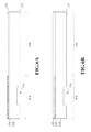
- FIGS. 6A-6D are schematic views showing a method for fabricating a touch panel with a fingerprint identification function according to some embodiments of the present disclosure:
- FIGS. 7A-7D are schematic views showing a method for fabricating a touch panel with a fingerprint identification function according to some embodiments of the present disclosure.
- FIG. 1 is a cross-sectional view of a touch panel 100 with a fingerprint identification function according to some embodiments of the present disclosure.
- the touch panel 100 includes a cover plate 110 , a mask layer 120 , a flexible substrate 130 , and a fingerprint sensing array 142 .
- the mask layer 120 is disposed on the cover plate 110 for defining an operating region OA and a non-operating region NA of the touch panel 100 .
- the flexible substrate 130 is disposed on the mask layer 120 and at least in the non-operating region NA.
- the fingerprint sensing array 142 is directly disposed on the flexible substrate 130 in the non-operating region NA.
- the touch panel 100 further includes an adhesive layer 150 disposed between the flexible substrate 130 and the mask layer 120 , and the adhesive layer 150 is configured to bond the flexible substrate 130 to the cover plate 110 .
- a transparent touch sensing array (not shown) is disposed in the operating region OA of the touch panel 100 , and the fingerprint sensing array 142 and other circuit configurations connected to the touch sensing, array are disposed in the non-operating region NA of the touch panel 100 .
- the fingerprint sensing, array 142 is initially formed on the flexible substrate 130 , and then the fingerprint sensing array 142 and the flexible substrate 130 are bonded with the cover plate 110 in the non-operating region NA through the adhesive layer 150 .
- the flexible substrate 130 has a small thickness and is bendable. Consequently, the combination of the fingerprint sensing array 142 and the flexible substrate 130 may be fitted with various cover plates of different sizes, types, or shapes, such as the cover plates having flat surfaces or tilted and curved surfaces, thereby realizing mass customization.
- the designs of this embodiment may reduce the distance between the fingerprint sensing array 142 and the surface 112 of the cover plate 110 . In other words, the distance between a user's fingers and the fingerprint sensing array 142 is reduced, thereby enhancing the sensitivity of fingerprint identification.
- the cover plate 110 is configured to hold plural components of the touch panel 100 , and has certain rigidity.
- a material forming the cover plate 110 may be glass or plastic.
- the cover plate 110 generally has high transmittance, such that the touch panel 100 may be fitted with a display panel (not shown) to form a touch display device.
- the mask layer 120 is disposed in the non-operating region NA for shielding the circuit configuration in the non-operating region NA.
- the mask layer 120 has low transmittance, and may be black ink, black photoresist, white ink, white photoresist, or stacked layers thereof.
- the mask layer 120 may be formed by various appropriate methods, such as coating or printing. Consequently, the non-operating region NA of the touch panel 100 is opaque, and the operating region OA is transparent, such that a user may not see the other circuit configuration in the non-operating region NA of the touch panel 100 .
- the flexible substrate 130 has better flexibility and a smaller thickness.
- the thickness of the flexible substrate is in a range from about 5 micrometers to about 35 micrometers.
- a material forming, the flexible substrate 130 may be polyvinyl chloride (PVC), polyimide (PI), polypropylene (PP), polystyrene (PS), acrylonitrile butadiene styrene (ABS), polyethylene terephthalate (PET), polycarbonate (PC), polyethylene (PE), or polymethylmethacrylate (PMMA).
- the flexible substrate 130 may be a thin film with a thickness in a range from about 1 micrometer to about 15 micrometers.
- the flexible substrate 130 may have a thickness in a range from about 2 micrometers to about 5 micrometers. In addition to the effect of reducing the distance, since the flexible substrate 130 has a small thickness, the volume of fingerprint sensors can be reduced and prevented from occupying much space.
- the fingerprint sensors can be attached to a flat surface or a tilted and curved surface of a component.
- the fingerprint sensing array 142 may be formed from at least one patterned conductive layer.
- the fingerprint sensing array 142 may be sensing electrodes of one single layer or sensing electrodes of two layers.
- the sensing electrodes of one single layer are used as an example of the fingerprint sensing array 142 .
- the patterned conductive layer may be formed on the flexible substrate 130 by fabrication processes such as deposition, lithography, and etching.
- the fingerprint sensing array 142 may be initially formed on the flexible substrate 130 and then bonded with the cover plate 110 .
- the fingerprint sensing array 142 may be formed from a transparent conductive material, such as indium tin oxide (ITO), aluminum-doped zinc oxide (AZO), zinc oxide (ZnO), antimony tin oxide (ATO), tin oxide (SnO 2 ), indium oxide (In 2 O 3 ), nano silver, nano copper, carbon nanotube or metal mesh.
- a transparent conductive material such as indium tin oxide (ITO), aluminum-doped zinc oxide (AZO), zinc oxide (ZnO), antimony tin oxide (ATO), tin oxide (SnO 2 ), indium oxide (In 2 O 3 ), nano silver, nano copper, carbon nanotube or metal mesh.
- the fingerprint sensing array 142 may be formed from an opaque conductive material, such as copper, silver, or other metal materials.
- a protective layer 160 may be optionally formed on the fingerprint sensing array 142 .
- the protective layer 160 is configured to protect the fingerprint sensing array 142 from scratches.
- the protective layer 160 may be a removable thin film.
- a material forming the protective layer 160 may be polyethylene terephthalate (PET), photoresist, silicon oxide, and so on.
- a thickness of the protective layer 160 is in a range from about 2 micrometers to about 15 micrometers.
- a portion of the cover plate 110 corresponding to the fingerprint sensing array 142 has a thickness smaller than a thickness of the cover plate 110 in the operating region OA.
- the cover plate 110 includes a first recess 114 formed in the non-operating region NA. Through the configuration of the first recess 114 , a distance between the surface 112 and the fingerprint sensing array 142 can be reduced, thereby increasing the sensitivity of fingerprint identification.
- the first recess 114 and the fingerprint sensing array 142 are disposed at two opposite sides of the cover plate 110 . That is, the first recess 114 is disposed adjoining, the surface 112 of the cover plate 110 .
- an orthographic projection of the first recess 114 on the cover plate 110 overlaps with an orthographic projection of the fingerprint sensing array 142 on the cover plate 110 .
- the cover plate 110 may not need to have the first recess 114 , and thus the configuration of the first recess 114 does not intend to limit the scope of the present disclosure.
- the fingerprint sensing array 142 is disposed at a side 132 of the flexible substrate 130 opposite to the cover plate 110 . That is, the fingerprint sensing array 142 is not disposed at the side 134 of the flexible substrate 130 which touches the adhesive layer 150 , and thus integrated circuit chips (not shown) can be electrically connected with the fingerprint sensing array 142 or subsequent circuits conveniently, but embodiments of the present disclosure are not limited thereto.
- FIG. 2 is a cross-sectional view of a touch panel 100 with a fingerprint identification function according to some embodiments of the present disclosure.
- the fingerprint sensing array 142 is disposed at a side 134 of the flexible substrate 130 facing the cover plate 110 .
- the distance between the fingerprint sensing, array 142 and the surface 112 may be reduced, thereby increasing the sensitivity of fingerprint identification.
- the fingerprint sensing array 142 is initially formed on the flexible substrate 130 , and then the fingerprint sensing array 142 and the flexible substrate 130 are bonded with the cover plate 110 through the adhesive layer 150 .
- a protective layer 160 may be disposed on the fingerprint sensing array 142 for protecting the fingerprint sensing array 142 from scratches.
- the protective layer 160 is removed, and the adhesive layer 150 may touch the fingerprint sensing array 142 directly.
- a protective layer (not shown) is still disposed on the fingerprint sensing array 142 , meaning that the protective layer (not shown) may be kept between the adhesive layer 150 and the fingerprint sensing array 142 , such that the adhesive layer 150 does not contact the fingerprint sensing array 142 directly,
- FIG. 3 is a cross-sectional view of a touch panel 100 with a fingerprint identification function according to some embodiments of the present disclosure.
- There is no adhesive layer 130 (referring to FIG. 1 ) configured to bond the flexible substrate 130 with the cover plate 110 in some embodiments.
- the flexible substrate 130 is a gel and is formed by applying the gel onto the mask layer 120 , such that the flexible substrate 130 is directly formed on the mask layer 120 .
- the gel may be an optical clear adhesive with high transmittance, a translucent adhesive, or an opaque adhesive.
- the gel may be adhered to the mask layer 120 in a conformal manner.
- a solidified optical clear adhesive is disposed as the flexible substrate 130 , and the fingerprint sensing, array 142 is directly disposed on the flexible substrate 130 (e. g. the solidified optical clear adhesive), such that the distance between the fingerprint sensing array 142 and the surface 112 may be reduced by omitting additional layers. The sensitivity of fingerprint identification is increased.
- FIG. 4 is a cross-sectional view of a touch panel 100 with a fingerprint identification function according to some embodiments of the present disclosure.
- the touch panel further includes a second recess 118 , and the fingerprint sensing array 142 is disposed in the second recess 118 .
- the second recess 118 is disposed adjacent to the surface 116 of the cover plate 110 , in which the surface 115 is opposite to the surface 112 .
- portions of the mask layer 120 , the flexible substrate 130 , and the adhesive layer 150 may be disposed in the second recess 118 .
- Integrated circuit chips electrically connected to the fingerprint sensing array 142 may be disposed on the flexible substrate 130 outside the second recess 118 .
- the mask layer 120 may be formed by methods such as deposition, lithography, and etching, and attached to the second recess 118 in a conformal manner.
- a material of the adhesive layer 150 may be a solid gel or a liquid gel, and therefore the adhesive layer 150 may be formed on the mask layer 120 in the conformal manner.
- the flexible substrate 130 is flexible, and therefore at least one portion of the flexible substrate 130 and the fingerprint sensing array 142 may be disposed in the second recess 118 , in which the flexible substrate 130 and the fingerprint sensing array 142 conform to the second recess.
- the distance between the surface 112 and the fingerprint sensing array 142 may be reduced, thereby increasing the sensitivity of fingerprint identification.
- the first recess 114 is not a necessary component.
- the first recess 114 may be omitted, while the second recess 118 is formed inside the touch panel 100 , such that the second recess 118 does not affect or destroy the appearance of the touch panel 100 . Therefore, the touch panel 100 is prevented from being damaged by stress concentration resulted from collisions, and the touch panel 100 may sustain the reliability thereof.
- the process of initially forming the fingerprint sensing array 142 on the flexible substrate 130 and then attaching the fingerprint sensing array 142 and the flexible substrate 130 to the second recess 188 is more feasible and may promote fabrication yield and efficiency.
- FIG. 5 is a cross-sectional view of a touch panel with a fingerprint identification function according to some embodiments of the present disclosure.
- the touch panel further includes a touch sensing array 114 , disposed in the operating region OA.
- the flexible substrate 130 is disposed in both the operating region OA and the non-operating region NA, and the touch sensing array 144 is disposed on the flexible substrate 130 in the operating region OA.
- the touch sensing array 144 may be formed by a transparent conductive material.
- the material of the fingerprint sensing array 142 may be the same as that of the touch sensing array 144 .
- the fingerprint sensing array 142 and the touch sensing array 144 in the operating region OA may be formed on the same flexible substrate 130 through the same fabrication processes, and then the adhesive layer 150 bonds the flexible substrate 130 with the cover plate 110 to form the touch panel 100 .
- the fingerprint sensing array 142 and the touch sensing array 144 may be formed from the same material through the same fabrication processes, but embodiments of the present disclosure are not limited thereto.
- the fingerprint sensing array 142 and the touch sensing array 144 may be formed from different materials, and formed on the flexible substrate 130 through different fabrication processes respectively or through partially the same fabrication processes. Then, the adhesive layer 150 bonds the flexible substrate 130 with the cover plate 110 to form the touch panel 100 .
- the flexible substrate 130 in the non-operating region NA and the operating region OA is continuously connected or integrally formed, but embodiments of the present disclosure are not limited thereto.
- the flexible substrate 130 where the fingerprint sensing array 142 and the touch sensing array 144 are arranged may be divided into a fingerprint sensing portion and a touch sensing portion which are attached to the cover plate 110 in the non-operating region NA and the operating region OA respectively. That is, the flexible substrate 130 in the non-operating region NA and the operating region OA may be disconnected.
- the touch panel 100 does not include the first recess 114 (referring to FIG. 1 ), and only the embodiment without the recess is provided herein, but embodiments of the present disclosure are not limited thereto.
- the touch panel 100 of the present embodiment may be configured with the first recess 114 .
- the fingerprint sensing array 142 and the touch sensing array 144 may be initially formed on the flexible substrate 130 . Since the fabrication steps of the fingerprint sensing array 142 and the touch sensing array 144 are similar, the fabrication steps may be combined and simplified, thereby reducing fabrication costs.
- FIGS. 6A-6D are schematic views showing a method for fabricating a touch panel 100 with a fingerprint identification function according to some embodiments of the present disclosure.
- the present disclosure provides the method for fabricating the touch panel 100 with a fingerprint identification function, and the method includes the following steps.
- a mask layer 120 is disposed on a cover plate 110 for defining an operating region OA and a non-operating region NA of the touch panel.
- the mask layer 120 may be formed by coating black inks.
- a gel 130 ′ is formed on at least the mask layer 120 by a process such as coating, and the gel 130 ′ is cured for forming the flexible substrate 130 (referring to FIG. 6C ), in which the flexible substrate 130 is disposed at least in the non-operating region NA.
- the flexible substrate 130 is a gel 130 ′, and the flexible substrate 130 is directly bonded with the cover plate 110 by coating the gel 130 ′.
- the gel 130 ′ may be coated on the mask layer 120 and portions of the cover plate 110 which are not covered by the mask layer 120 , such that the flexible substrate 130 (referring FIG. 6C ) is disposed in the non-operating region NA and the operating region OA.
- additional protective layers may be formed thereon and then removed in subsequent processes. For example, the additional protective layers may be removed after a conductive layer 140 ′ is formed as shown in FIG. 6C .
- the conductive layer 140 ′ is formed on the flexible substrate 130 .
- a material forming the conductive layer 140 ′ may be a transparent conductive material.
- the conductive layer 140 ′ may be formed on the flexible substrate 130 by deposition or other methods.
- the conductive layer 140 ′ is patterned to form a fingerprint sensing army 142 on the flexible substrate 130 in the non-operating region NA and a touch sensing array 144 on the flexible substrate 130 in the operating region OA.
- the fingerprint sensing array 142 is configured to detect a user's fingerprint
- the touch sensing array 144 is configured to detect touch positions of the user's fingers.
- the electrode configurations of the fingerprint sensing array 142 and the touch sensing array 144 may be different.
- the first recess 114 and the fingerprint sensing array 142 are disposed at two opposite sides of the cover plate 110 , and an orthographic projection of the first recess 114 on the cover plate 110 overlaps with an orthographic projection of the fingerprint sensing array 142 on the cover plate 110 .
- an integrated circuit chip (not shown) configured to process fingerprint sensing information is attached to the flexible substrate 130 , and is electrically connected to the fingerprint sensing array 142 . Since the integrated circuit chip (not shown) is directly bonded with the fingerprint sensing array 142 , the signal transmitting path can be reduced, and the inspection precision of the fingerprint sensing array can be enhanced. Through the configuration, the touch panel 100 can inspect the user's fingerprint by the fingerprint sensing array 142 disposed on the flexible substrate 130 , thus achieving the purpose of fingerprint identification.
- FIGS. 7A-7D are schematic views showing a method for fabricating a touch panel with a fingerprint identification function according to some embodiments of the present disclosure.
- the present disclosure provides the method for fabricating the touch panel 100 with a fingerprint identification function, and the method includes the following steps.
- a mask layer 120 is disposed on the cover plate 110 for defining the non-operating region NA and the operating region OA.
- a first recess 114 may be optionally formed on the surface 112 of the cover plate 110 in the non-operating region NA, or a second recess (not shown) may be optionally formed on the surface 116 in the non-operating region NA
- the mask layer 120 may be formed by coating black inks.
- a conductive layer 140 ′ is formed on the flexible substrate 130 .
- the flexible substrate 130 since the flexible substrate 130 is thin and flexible, the flexible substrate 130 may be formed on a plate 200 or other protection films before the conductive layer 140 ′ is formed on the flexible substrate 130 .
- the plate 200 is capable of supporting the flexible substrate 130 in the subsequent fabrication process, but does not constitute the finished touch panel.
- the flexible substrate 130 may be formed from an optical clear adhesive with protection films (not shown) disposed on upper and lower surfaces of the optical clear adhesive. Before the conductive layer 140 ′ is formed, one of the protection films may be removed, and then the conductive layer 140 ′ is disposed on the surface of the optical clear adhesive (the flexible substrate 130 ).
- a material of the conductive layer 140 ′ may be one of transparent conductive materials.
- a material of the flexible substrate 130 may be polyvinyl chloride (PVC), polyimide (PI), polypropylene (PP), polystyrene (PS), acrylonitrile butadiene styrene (ABS), polyethylene terephthalate (PET), polycarbonate (PC), polyethylene (PE), or polymethylmethacrylate (PMMA).
- PVC polyvinyl chloride
- PI polyimide
- PP polypropylene
- PS polystyrene
- ABS acrylonitrile butadiene styrene
- PET polyethylene terephthalate
- PC polycarbonate
- PE polyethylene
- PMMA polymethylmethacrylate
- the conductive layer 140 may be formed on the flexible substrate 130 by deposition or other methods.
- the conductive layer 140 ′ is patterned to form a fingerprint sensing array 142 and a touch sensing array 144 on the flexible substrate 130 .
- the fingerprint sensing array 142 and the touch sensing array 144 respectively correspond to the non-operating region NA (referring to FIG. 7A ) and the operating region OA (referring to FIG. 7A ) of the touch panel.
- the fingerprint sensing array 142 and the touch sensing array 144 may be formed by the same fabrication processes for simplifying the fabrication processes, but embodiments of the present disclosure are not limited thereto.
- the fingerprint sensing array 142 and the touch sensing array 144 may be formed through different fabrication processes.
- a protective layer 160 is formed on the fingerprint sensing array 142 . Furthermore, before the cover plate 110 is bonded with the flexible substrate 130 , the flexible substrate 130 is separated from the plate 200 or other protection films. In some embodiments, the protective layer 160 is removed, and a side of the flexible substrate 130 is to be bonded with the cover plate 110 .
- the flexible substrate 130 and the cover plate 110 are bonded by adhesive layer 150 , in which a side of the flexible substrate 130 is bonded with the cover plate 110 .
- the fingerprint sensing array 142 is disposed in the non-operating region NA (referring to FIG. 7A )
- the touch sensing array 144 is disposed in the operating region OA (referring to FIG. 7A ).
- the first recess 114 and the fingerprint sensing array 142 are disposed at two opposite sides of the cover plate 110 , and an orthographic projection of the first recess 114 on the cover plate 110 overlaps with an orthographic projection of the fingerprint sensing array 142 on the cover plate 110 .
- the cover plate 110 includes the second recess (not shown)
- the flexible substrate 130 and the fingerprint sensing array 142 are disposed in the second recess (not shown) and conform to the second recess (not shown).
- integrated circuit chips (not shown) configured to process fingerprint sensing information are attached to the flexible substrate 130 , and are electrically connected to the fingerprint sensing array 142 .
- the touch panel 100 can inspect the fingerprint of users by the fingerprint sensing array 142 disposed on the flexible substrate 130 , thus achieving the purpose of fingerprint identification.
- a fingerprint sensing array is disposed on a flexible substrate. Since the flexible substrate is thin and flexible, the flexible substrate adheres and conforms to the cover plate, thereby reducing the distance between the fingerprint sensing array and the finger. In addition, in various embodiments of the present disclosure, integrated circuit chips and the fingerprint sensing array are disposed separately, thereby resolving the problems that the conventional fingerprint sensor chips occupies too much space.
Landscapes
- Engineering & Computer Science (AREA)
- Theoretical Computer Science (AREA)
- General Engineering & Computer Science (AREA)
- Human Computer Interaction (AREA)
- Physics & Mathematics (AREA)
- General Physics & Mathematics (AREA)
- Multimedia (AREA)
- Position Input By Displaying (AREA)
- Image Input (AREA)
- Measurement Of Length, Angles, Or The Like Using Electric Or Magnetic Means (AREA)
Abstract
Description
Claims (20)
Applications Claiming Priority (3)
| Application Number | Priority Date | Filing Date | Title |
|---|---|---|---|
| CN201510382111 | 2015-07-03 | ||
| CN201510382111.8 | 2015-07-03 | ||
| CN201510382111.8A CN105528104A (en) | 2015-07-03 | 2015-07-03 | A touch control panel having a fingerprint identification function and a method for manufacturing the same |
Publications (2)
| Publication Number | Publication Date |
|---|---|
| US20170004343A1 US20170004343A1 (en) | 2017-01-05 |
| US10514798B2 true US10514798B2 (en) | 2019-12-24 |
Family
ID=55770375
Family Applications (1)
| Application Number | Title | Priority Date | Filing Date |
|---|---|---|---|
| US15/201,509 Active 2036-12-22 US10514798B2 (en) | 2015-07-03 | 2016-07-04 | Touch panel with fingerprint identification function and method for fabricating the same |
Country Status (2)
| Country | Link |
|---|---|
| US (1) | US10514798B2 (en) |
| CN (1) | CN105528104A (en) |
Families Citing this family (15)
| Publication number | Priority date | Publication date | Assignee | Title |
|---|---|---|---|---|
| CN108599310B (en) | 2015-12-03 | 2020-07-10 | Oppo广东移动通信有限公司 | Charging method and mobile terminal |
| KR102622021B1 (en) * | 2016-08-03 | 2024-01-08 | 삼성전자 주식회사 | Electronic device having finger print sensor |
| CN108462768B (en) * | 2016-08-16 | 2019-07-19 | Oppo广东移动通信有限公司 | Fingerprint module, fingerprint module manufacturing method and mobile terminal |
| EP3285207A1 (en) * | 2016-08-16 | 2018-02-21 | Guangdong Oppo Mobile Telecommunications Corp., Ltd | Input assembly and manufacturing method |
| ES2714181T3 (en) * | 2016-08-16 | 2019-05-27 | Guangdong Oppo Mobile Telecommunications Corp Ltd | Fingerprint sensor, method for manufacturing a fingerprint and terminal sensor |
| CN106295590A (en) * | 2016-08-16 | 2017-01-04 | 广东欧珀移动通信有限公司 | Fingerprint module, fingerprint module manufacture method and mobile terminal |
| EP3288246A1 (en) | 2016-08-16 | 2018-02-28 | Guangdong Oppo Mobile Telecommunications Corp., Ltd | Fingerprint module and method for manufacturing the fingerprint module |
| CN106249961B (en) * | 2016-09-12 | 2018-12-21 | 京东方科技集团股份有限公司 | Production method, touch display screen and the display device of touch display screen |
| CN107480639B (en) * | 2017-08-16 | 2020-06-02 | 上海天马微电子有限公司 | Touch display panel and display device |
| CN107633234B (en) * | 2017-09-26 | 2020-07-28 | 北京集创北方科技股份有限公司 | Detection method and device for fingerprint identification system |
| CN108196626B (en) * | 2018-01-17 | 2023-08-29 | 南昌黑鲨科技有限公司 | Screen assembly and intelligent terminal with same |
| CN108282570B (en) * | 2018-01-22 | 2020-05-08 | Oppo广东移动通信有限公司 | Electronic device |
| TWI755076B (en) * | 2020-05-05 | 2022-02-11 | 神盾股份有限公司 | Electronic device |
| US20240161534A1 (en) * | 2021-03-23 | 2024-05-16 | Fingerprint Cards Anacatum Ip Ab | Fingerprint sensor module and method for manufacturing a fingerprint sensor module |
| US12298183B2 (en) * | 2023-01-31 | 2025-05-13 | Innolux Corporation | Flexible sensing device and method for manufacturing the same |
Citations (6)
| Publication number | Priority date | Publication date | Assignee | Title |
|---|---|---|---|---|
| US20110309482A1 (en) * | 2010-06-18 | 2011-12-22 | Authentec, Inc. | Finger sensor including encapsulating layer over sensing area and related methods |
| US20120092350A1 (en) * | 2010-10-18 | 2012-04-19 | Qualcomm Mems Technologies, Inc. | Wraparound assembly for combination touch, handwriting and fingerprint sensor |
| US20120242635A1 (en) * | 2009-10-30 | 2012-09-27 | Validity Sensors, Inc., a Delaware Corporation | Fingerprint sensor and integratable electronic display |
| US20130307818A1 (en) * | 2012-05-18 | 2013-11-21 | Apple Inc. | Capacitive Sensor Packaging |
| US20140103943A1 (en) * | 2012-10-14 | 2014-04-17 | Synaptics Incorporated | Fingerprint sensor and button combinations and methods of making same |
| US20150187707A1 (en) * | 2012-10-14 | 2015-07-02 | Synaptics Incorporated | Biometric Image Sensor Packaging and Mounting |
Family Cites Families (3)
| Publication number | Priority date | Publication date | Assignee | Title |
|---|---|---|---|---|
| CN203930873U (en) * | 2014-07-02 | 2014-11-05 | 南昌欧菲生物识别技术有限公司 | Fingerprint Identification sensor, integrated package and electronic installation |
| CN204242132U (en) * | 2014-09-11 | 2015-04-01 | 宸鸿科技(厦门)有限公司 | Contactor control device |
| CN104700084A (en) * | 2015-03-06 | 2015-06-10 | 南昌欧菲生物识别技术有限公司 | Fingerprint recognition device, touch screen with same and terminal device |
-
2015
- 2015-07-03 CN CN201510382111.8A patent/CN105528104A/en active Pending
-
2016
- 2016-07-04 US US15/201,509 patent/US10514798B2/en active Active
Patent Citations (6)
| Publication number | Priority date | Publication date | Assignee | Title |
|---|---|---|---|---|
| US20120242635A1 (en) * | 2009-10-30 | 2012-09-27 | Validity Sensors, Inc., a Delaware Corporation | Fingerprint sensor and integratable electronic display |
| US20110309482A1 (en) * | 2010-06-18 | 2011-12-22 | Authentec, Inc. | Finger sensor including encapsulating layer over sensing area and related methods |
| US20120092350A1 (en) * | 2010-10-18 | 2012-04-19 | Qualcomm Mems Technologies, Inc. | Wraparound assembly for combination touch, handwriting and fingerprint sensor |
| US20130307818A1 (en) * | 2012-05-18 | 2013-11-21 | Apple Inc. | Capacitive Sensor Packaging |
| US20140103943A1 (en) * | 2012-10-14 | 2014-04-17 | Synaptics Incorporated | Fingerprint sensor and button combinations and methods of making same |
| US20150187707A1 (en) * | 2012-10-14 | 2015-07-02 | Synaptics Incorporated | Biometric Image Sensor Packaging and Mounting |
Also Published As
| Publication number | Publication date |
|---|---|
| CN105528104A (en) | 2016-04-27 |
| US20170004343A1 (en) | 2017-01-05 |
Similar Documents
| Publication | Publication Date | Title |
|---|---|---|
| US10514798B2 (en) | Touch panel with fingerprint identification function and method for fabricating the same | |
| US10198131B2 (en) | Touch control device | |
| US9772730B2 (en) | Touch panel with function of fingerprint identification | |
| KR101758187B1 (en) | Touch control device | |
| US9915979B2 (en) | Input device, display device, electronic device, and mobile terminal | |
| CN103576949B (en) | Touch panel and manufacturing method thereof | |
| KR102754103B1 (en) | Display device and manufacturing method thereof | |
| US10146347B2 (en) | Display device having an integrated display panel and touch panel | |
| CN203982334U (en) | The contact panel with fingerprint identification function | |
| US20160034078A1 (en) | Touch device | |
| US20170228075A1 (en) | Pressure sensing display and manufacturing method thereof | |
| US20150301669A1 (en) | Input device, display device, and electronic apparatus | |
| KR20170047426A (en) | Touch display device and method of manufacturing the same | |
| US11966546B2 (en) | Display device, fabrication method of display device, and fabrication method of light guide touch module | |
| US20150145804A1 (en) | Touch apparatus | |
| CN112447928A (en) | Display device | |
| JP5869591B2 (en) | Input device, display device, and electronic device | |
| JP3167028U (en) | Decorative frame for touch panel | |
| TWI486857B (en) | Touch module | |
| CN103885649A (en) | Touch module | |
| CN104978067A (en) | Touch panel | |
| JP5812877B2 (en) | Input device, display device, and portable terminal | |
| CN105302377A (en) | Protective cover plate and touch device applying same | |
| US11151347B1 (en) | Touch-fingerprint complex sensor and method of fabricating the same | |
| CN204480194U (en) | Contactor control device |
Legal Events
| Date | Code | Title | Description |
|---|---|---|---|
| STPP | Information on status: patent application and granting procedure in general |
Free format text: FINAL REJECTION MAILED |
|
| STPP | Information on status: patent application and granting procedure in general |
Free format text: RESPONSE AFTER FINAL ACTION FORWARDED TO EXAMINER |
|
| STPP | Information on status: patent application and granting procedure in general |
Free format text: ADVISORY ACTION MAILED |
|
| STPP | Information on status: patent application and granting procedure in general |
Free format text: DOCKETED NEW CASE - READY FOR EXAMINATION |
|
| STPP | Information on status: patent application and granting procedure in general |
Free format text: NOTICE OF ALLOWANCE MAILED -- APPLICATION RECEIVED IN OFFICE OF PUBLICATIONS |
|
| STPP | Information on status: patent application and granting procedure in general |
Free format text: NOTICE OF ALLOWANCE MAILED -- APPLICATION RECEIVED IN OFFICE OF PUBLICATIONS |
|
| STPP | Information on status: patent application and granting procedure in general |
Free format text: PUBLICATIONS -- ISSUE FEE PAYMENT VERIFIED |
|
| STCF | Information on status: patent grant |
Free format text: PATENTED CASE |
|
| MAFP | Maintenance fee payment |
Free format text: PAYMENT OF MAINTENANCE FEE, 4TH YEAR, LARGE ENTITY (ORIGINAL EVENT CODE: M1551); ENTITY STATUS OF PATENT OWNER: LARGE ENTITY Year of fee payment: 4 |
|
| AS | Assignment |
Owner name: ALPHA TOUCH GROUP LLC, TEXAS Free format text: ASSIGNMENT OF ASSIGNORS INTEREST;ASSIGNOR:TPK TOUCH SOLUTIONS (XIAMEN) INC.;REEL/FRAME:072447/0061 Effective date: 20250725 |