US1050960A - Electrical reciprocating mechanism. - Google Patents
Electrical reciprocating mechanism. Download PDFInfo
- Publication number
- US1050960A US1050960A US22046804A US1904220468A US1050960A US 1050960 A US1050960 A US 1050960A US 22046804 A US22046804 A US 22046804A US 1904220468 A US1904220468 A US 1904220468A US 1050960 A US1050960 A US 1050960A
- Authority
- US
- United States
- Prior art keywords
- coil
- core
- sections
- bore
- coils
- Prior art date
- Legal status (The legal status is an assumption and is not a legal conclusion. Google has not performed a legal analysis and makes no representation as to the accuracy of the status listed.)
- Expired - Lifetime
Links
- 230000007246 mechanism Effects 0.000 title description 24
- 230000005291 magnetic effect Effects 0.000 description 24
- XEEYBQQBJWHFJM-UHFFFAOYSA-N Iron Chemical compound [Fe] XEEYBQQBJWHFJM-UHFFFAOYSA-N 0.000 description 12
- 239000004020 conductor Substances 0.000 description 12
- 238000004804 winding Methods 0.000 description 9
- 238000010276 construction Methods 0.000 description 5
- 230000005298 paramagnetic effect Effects 0.000 description 5
- 229910001369 Brass Inorganic materials 0.000 description 4
- 239000010951 brass Substances 0.000 description 4
- 230000000694 effects Effects 0.000 description 4
- 239000011810 insulating material Substances 0.000 description 4
- 229910052742 iron Inorganic materials 0.000 description 4
- 230000009471 action Effects 0.000 description 3
- 230000006872 improvement Effects 0.000 description 3
- 239000002184 metal Substances 0.000 description 3
- 229910052751 metal Inorganic materials 0.000 description 3
- 238000005266 casting Methods 0.000 description 1
- 230000008859 change Effects 0.000 description 1
- 230000002301 combined effect Effects 0.000 description 1
- 238000010586 diagram Methods 0.000 description 1
- 238000009413 insulation Methods 0.000 description 1
- 150000002500 ions Chemical class 0.000 description 1
- 230000004048 modification Effects 0.000 description 1
- 238000012986 modification Methods 0.000 description 1
- 239000002907 paramagnetic material Substances 0.000 description 1
- 238000005192 partition Methods 0.000 description 1
- 229920000136 polysorbate Polymers 0.000 description 1
- 230000000284 resting effect Effects 0.000 description 1
- 239000002023 wood Substances 0.000 description 1
Images

Classifications
-
- H—ELECTRICITY
- H02—GENERATION; CONVERSION OR DISTRIBUTION OF ELECTRIC POWER
- H02K—DYNAMO-ELECTRIC MACHINES
- H02K33/00—Motors with reciprocating, oscillating or vibrating magnet, armature or coil system
- H02K33/12—Motors with reciprocating, oscillating or vibrating magnet, armature or coil system with armatures moving in alternate directions by alternate energisation of two coil systems
- H02K33/14—Motors with reciprocating, oscillating or vibrating magnet, armature or coil system with armatures moving in alternate directions by alternate energisation of two coil systems wherein the alternate energisation and de-energisation of the two coil systems are effected or controlled by movement of the armatures
Definitions
- -My invention relates to electrical motor mechanism for effecting a reciprocating motion, its object'being to secure a construction more efficient and economical than has heretofore been efiected.
- Devices for electrically producing a reciprocatory motion have heretofore been constructed, but in so.
- I I may refer to the patents to Van Depoele, 450,543, April 14th, 1891, and to Marvin, 368,405, August 16th, 1887, as exemplifying the prior art and as constituting the nearest approach thereof to my ,iprescnt improvements.
- Infihe one an electromagnetic structure comprising a single coil and numerous magnetic circuit-closing "parts, is designed to draw the piston into the coil, and permit it to fall back upon cutting off the exciting CLMlQnlJ.
- the other patent shows a sub-divided solenoid acting alternately upon two associatedimagnetic cores," and controlled by an extraneous switclung-mechanism for effecting the reciprocation of said connected cores.
- the embodiment of my invention utilizes certain features set forth in theseipatents, com bined in a novel manner with improvements of my own.
- the present structure may be described in a preliminary way as comprising a series of exciting coils, forming a singlecoil-structure, sub-divide .by alternating magnetic circuit-closing parts, which preferably serve as well, the ,function of making'electrical connection withatheir respective coils.
- netic shell or envelop intimately associated with the magnetic circuit-closing parts.
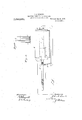
- Figure 1 represents a longitudinal axial section of an electric motor device embodying my invention, portions cut by the axialplane being shown in elevation.
- Fig. 2 represents a transverse cross-section of the inner portion of the device including the movable core, the section being taken upon the plane in dicated by line 22 in Fig. 1. and viewed as indicated by the arrows.
- Fig. 3 represents a side elevation of the movable core and broken portions of conductor rods and taken-upon the plane indicated by line 4.4,
- Fig. 5 represents a similar section taken upon line 5-5 of said figure and viewed in the direction indicated bythe arrows.
- Fig. 6, represents a side elevation of a modified form of the invention, and Fig. 6 is a fragmentary diagram showing the serial connection of the coils and disks, indicat ing by dotted lines, the path of the movable core.
- the two main elements of my invention as illustrated in the drawings consist of an outer coil structure and an inner movable core, constructed in a manner hereinafter fully described.
- the construction and operation of the device is, broadly speaking, substantially similar tothat of an ordinary solenoid and movable core therefor.
- I have been enabled to overcome the difficulties heretofore encountered in utilizing the ordinary sole noid and movable core for effecting a reciprocating motion and attain an efliciency in my improved mechanism substantially equal to that obtained in the rotary electric motors at present in use.
- the outer or coil structure consists primarily of a series of coil-sections numbered from 1 to 19 inclusive in the drawing. These coil-sections are coaxialas shown, and. are separated as will hereinafter appear, by metal disks, the coils and disks being connected in series and arranged alternately with respect to each other in the direction of such coil action.
- the interior space formed by these coils and disks is lined with a contact surface consisting of alternately occurring conducting and in sulating sections which are formed in the following manner.
- Upon the interior surface of the rings and coil-sections are sccured alternately occurring metal rings B and insulating rings Z), shown in Fig. 1.
- the metal rings which are constructed of iron, are placed midway between each two adjacent coils and are separated from each other by means of the insulating ring 5, as shown.
- Two terminal iron rings 15 project beyond the terminal coils shown, forming terminal sections of said contact surface.
- each iron ring is provided upon its inner surface with a thin brass ring or lining 7) which, however, may be considered a part of the iron ring in so far as concerns the purposes of this invention.
- the outer and inner-diameters of the -coils and intermediate paramagnetic or iron disks C are equal to each other as shown, and surrounding the numsurface of the said coils and disks is a succession of iron rings 7) equal in, number and similar in longitudinal location to the rings B. These latter rings are also separated from each other by means ofthin insulating rings Z) as shown.
- Each disk C and its two contacting rings including the brass lining may be considered one integral con struction, in so far as its action and ,function are concerned, and may, in fact, be made integral with each other if desired.
- the number of'disks C is equal to the number of coil sections, so that at one end of the coil structure a terminal is formed by a disk, and at the other end of the structure a terminal is formed by the end of the terminal coil section, as will be readily understood.
- the coil section number 1 on the left one end thereof is electrically connected with the end of terminal disk C, the other end of such coil being connected with the next fol-- lowing disk C, to which latter one end of the coil 2 is connected. All of the disks and coils are connected in a similar manner so that-it will be observed the entire series of coils and disks is connected electrically in series.
- the conducting surface sections formed by the brass rings 7 accordingly comprise a succession of contacts by means of which the coil may be tapped at various points in the direction of the coil axis.
- the outer cylindrical surface of the coil structure is surrounded by a suitable insulating material (2.
- an aperture which is provided with a bushing f, forming a bearing for a draft rod to the inner end of which is secured the movable core G.
- the main or body portion r/ of this core is made of iron and is formed at its respective ends with conical recesses g.
- caps H and I made of brass or other nonrmagnetickmaterial, suitably insulated lfiom the main or body portion and secured thereto by properly insulated. screws h and portion of adiameter substantially equal tothe interior diameter of the bore or cont-act surface.
- the diameter of the body portion is made slightly less than the diameter'of such bore, so that it will be seen the core may move through the bore resting upon the flange portions of the end caps H and I the edge of the latter being indicated at d, Fig. 5'.
- Passingthrough the core and parallel with the axis of the latter are two long bores g g", which receive the conduct- "in rods 6 and e res ectivel ,as shown.
- Rod e is out of contact with or insulated from cap I and the body portion of the core extending, as it does, through the expanded opening 11 and the insulating sleeve g, but in. electrical sliding contact withthe cap' H, as 'shownin Fig. 1.
- the cap I in In a 'similar manner slots are provided in which are located respectively two springs 2 one, of which maintains contact between itself andjsaid contact surface or bore, and betweenitself and the rod, 6
- the outer ends of the two conducting rods 6 and c are connected with two wires 8 and 19', connected with suitable terminals Whereby either one ⁇ may be connected by means of a switch S to the main wire 8
- a second terminal f of the manner line wire is connected with the bushing f and to the latter with draft rod gt, the latter beingsecurely threaded or fastened into the main or body portion of thecore, passing through the cap II and being out of contact withthe latter, as shown.
- the above described device operates as follows :Assuming that the current is turned into the rod (1 and that the parts occupy the position illustrated, such currentwill pass from the rod into cap I, spring contact fingers i i and thence into the coil section of winding number 8, through'sa'id winding and also through windings 7, 6 and 5, in series, to the ring B, connected wan number 5, thence through spring contact fingers g g to the body of the plunger,
- the said fie d is therefore substantially fixed relatively to the core; and movable relatively to the coil. In this manner it will be observed only the required numberof coil-sections is permitted to re: remain in the electrical circuit so that the electrical resistance is reduced to a minimunrr thence to the draft rod g, bushing f and line one end of the core.
- each group of coils when active forms a solenoid having a substantially closed para-magnetic circuit including the core itself, the separating disks or partitions (l opposite the core, rings B and b and the outer inclosing casing or jacket D.
- Each roup of active coilsections becomes a highly etficient solenoid by reason of the above described construction.
- the return magnetic flow is always effected through that end of the core projecting from the particular solenoid then in action, so that the return portion of the magnetic circuit bears a substantially constant relation to the active. solenoid whichever group of coil sect-ions may be included in such solenoid.
- the elliciency of a solenoid isdependent upon the electrical resistance of the solenoid circuit; the resistance of said circuit depends upon the cross-section and length of the conducting wire and hence varies inversely as the cross-section and directly as the number of turns; and the number of ampere turns which are employed to produce a given ctl'ect by means of a given current varies directly as the reluctance of the magnetic circuit of the solenoid.
- the combination with a sub-divided coil of means for maintaining a constant fraction of said coil active, a movable member con tinuously influenced, and partly surrounded by such coiltraction, means for changing the location of the latter along the coil axis synchronously with the movement of said movable member, comprising traveling brushes thereon and interiorly positionedcontact-s engaged thereby, and means for re versing the location of saidcoil-fraction relativelv to said movable member.
- the other contact being insulated from said first named contact and also arranged to contact said rings.
- each ring connected or provided With a disk electrically connected therewith, said disks and sections being alternately arranged along the bore axis and electrically in series, a metallic casing surrounding said sections and insulated from said disks, a core movable in said bore, three contacts carried by said core, arranged SUCCESSlVGlY in the direction of the bore axis, and two conductors, the intermediate contact being connected with said core and arranged to contact said rings, and the other two contacts being also arranged to contact said rings, said latter contacts being insulated from said core and electrically connected with said two conductors respectively.
- a magnetizing coil-circuit of constant length a movable core controlled by said coil-circuit-ip ettect its reciprocation therein, and a symmetrical magnetic structure, comprising means for maintaining the area of the ortions of the magnetic circuit conducting -lie lines of force out of the core and into the core constant during each reciprocatory movement of the latter comprising contact brushes carried by the core and co-acting contacts within the coils.
- a reciprocatory electric motor the combination with a subdivided helix or Winding forming the fieldcoil, of a paramagnetic movable member or armature mounted to reciprocate therein, conductingcontacts forming terminals of the subdivisions of the field-coil, brushes or traveling contacts carried by the armature positioned to direct current through successive portions of the field-coil effectively in advance of the armature in its direction of movement, and adjacent magnetic conductors disposed along the path of movement of the armature in position to close successively the magnetic circuit t-therethrough during the movement of the armature, substantially as set forth.
- a reciprocatory motor structure a plurality of serially-connected field-coils, magnetic-circuit closing parts alternating with portions thereof, a reciprocating armature-partot para-magnetic material actuated by the former, and electrical-circuit, closing mechanism or means for directing current through portions of the field-coil structure successively in advance of the center of fig are of said armature-part,- substantially as set forth.
- the combination with a coil-structure consisting of a plurality of sections, of parts for closing the magnetic circuit, alternating with said sections, and forming electrical contacts through Which the coil structure receives its current.
Landscapes
- Engineering & Computer Science (AREA)
- Power Engineering (AREA)
- Electromagnets (AREA)
Description
J. O. LINCOLN.
ELECTRICAL REGIPROGATING MECHANISM. APPLICATION FILED AUG.12, 1904.
1,050,960. Patented Jan.21,1913.
2 SHEETS-SHEET 1.
J. O. LINCOLN.
ELECTRICAL REGIPROOATING MEGHANISM.
APPLIOATION FILED AUG.1Z, 1904.
Patenteol Jan. 21, 1913.
2 BEBETS-SHBET 2.
M4 TNES-S Es,-
UNH
JOHN C. Lniconn,
To all whom it may concern:
Be it-known thatI, JOHN C. LINCOLN, a. Icitizen of the United States, resident of Cleveland, county of- Cuyahoga, and State 'of Ohio, have invented a new and useful Improvement in Electrical Reciprocating Mechanism, of which the following isa specification, the principle of the invention being herein explained and the best mode in which I have contemplated applying that principle, so as to distinguish it from other inventions.
-My invention relates to electrical motor mechanism for effecting a reciprocating motion, its object'being to secure a construction more efficient and economical than has heretofore been efiected. Devices for electrically producing a reciprocatory motion have heretofore been constructed, but in so.
far as I am aware, theireiiiciency has been so low as to render them impracticable from a commercial standpoint.
-My'said invention consists'of means hereinafter fully described and particularly set forthgin the claims. I I may refer to the patents to Van Depoele, 450,543, April 14th, 1891, and to Marvin, 368,405, August 16th, 1887, as exemplifying the prior art and as constituting the nearest approach thereof to my ,iprescnt improvements. Infihe one an electromagnetic structure comprising a single coil and numerous magnetic circuit-closing "parts, is designed to draw the piston into the coil, and permit it to fall back upon cutting off the exciting CLMlQnlJ. The other patent shows a sub-divided solenoid acting alternately upon two associatedimagnetic cores," and controlled by an extraneous switclung-mechanism for effecting the reciprocation of said connected cores. The embodiment of my invention utilizes certain features set forth in theseipatents, com bined in a novel manner with improvements of my own. The present structure may be described in a preliminary way as comprisinga series of exciting coils, forming a singlecoil-structure, sub-divide .by alternating magnetic circuit-closing parts, which preferably serve as well, the ,function of making'electrical connection withatheir respective coils.
netic shell or envelop intimately associated with the magnetic circuit-closing parts.
Specification of Letters Patent.
exterior to ,all is a mag-- OF CLEVELAND, CHIC, ASSIGNOR TO THE LINCOLN COMPANY, OF
CLEVELAND, OHIO, A. CQRIEORATION OLE OHIO.
ELECTRICAL RECIPRUCATING MECHANISM.
Patented Jan. 21,1913.
Application filed August 12, 1904. Serial No. 220,468.
Within said coils, and the magnetic sys- This movable member or core, accordingly forms part of complete magnetic and electrical systems synchronously traveling therewith in effect, to cause the rapid movement of the said core. Thus my improved reciprocating motor is distinguished in several important particulars, structurally set forth in the claims. The most salient of these may be contradistinguished from the art by pointing out that a single relatively short core, acted upon alternately from either end by a group of exciting coils approximating but a fraction of its length, is mounted for reciprocation within the structure. By reason of the arrangement herein set forth, moreover, only the coils positioned to exert the maximum effect are suc cessively maintained in circuit, While in any position of the traveling .core or movable body, the magnetic system successively accommodates itself for most effectively closing the lines of force produced, through the body of said core.
The annexed drawings and the following description set forth in'detail certain mechanism embodying the invention, such disclosed means constituting but one of various mechanical forms in which the principle of the invention may be used.
In said annexed drawings :Figure 1 represents a longitudinal axial section of an electric motor device embodying my invention, portions cut by the axialplane being shown in elevation. Fig. 2 represents a transverse cross-section of the inner portion of the device including the movable core, the section being taken upon the plane in dicated by line 22 in Fig. 1. and viewed as indicated by the arrows. Fig. 3 represents a side elevation of the movable core and broken portions of conductor rods and taken-upon the plane indicated by line 4.4,
3, and viewed in the direction indiacted-by the arrows adjacent-.110 this-line.
Fig. 5 represents a similar section taken upon line 5-5 of said figure and viewed in the direction indicated bythe arrows. Fig. 6, represents a side elevation of a modified form of the invention, and Fig. 6 is a fragmentary diagram showing the serial connection of the coils and disks, indicat ing by dotted lines, the path of the movable core.
The two main elements of my invention as illustrated in the drawings, consist of an outer coil structure and an inner movable core, constructed in a manner hereinafter fully described. The construction and operation of the device is, broadly speaking, substantially similar tothat of an ordinary solenoid and movable core therefor. By means of certain modifications and improvements, however, I have been enabled to overcome the difficulties heretofore encountered in utilizing the ordinary sole noid and movable core for effecting a reciprocating motion and attain an efliciency in my improved mechanism substantially equal to that obtained in the rotary electric motors at present in use.
The outer or coil structure consists primarily of a series of coil-sections numbered from 1 to 19 inclusive in the drawing. These coil-sections are coaxialas shown, and. are separated as will hereinafter appear, by metal disks, the coils and disks being connected in series and arranged alternately with respect to each other in the direction of such coil action. The interior space formed by these coils and disks is lined with a contact surface consisting of alternately occurring conducting and in sulating sections which are formed in the following manner. Upon the interior surface of the rings and coil-sections are sccured alternately occurring metal rings B and insulating rings Z), shown in Fig. 1. The metal rings, which are constructed of iron, are placed midway between each two adjacent coils and are separated from each other by means of the insulating ring 5, as shown. Two terminal iron rings 15 project beyond the terminal coils shown, forming terminal sections of said contact surface. As shown in the drawing each iron ring is provided upon its inner surface with a thin brass ring or lining 7) which, however, may be considered a part of the iron ring in so far as concerns the purposes of this invention. The outer and inner-diameters of the -coils and intermediate paramagnetic or iron disks C are equal to each other as shown, and surrounding the numsurface of the said coils and disks is a succession of iron rings 7) equal in, number and similar in longitudinal location to the rings B. These latter rings are also separated from each other by means ofthin insulating rings Z) as shown. The inner surface of each disk cepting upon the interior of the bore.
C is in electrical contact with the middle portion of the ring B as shown, and the outer surface of such disk is similarly in contact with a ring 7). Each disk C and its two contacting rings including the brass lining may be considered one integral con struction, in so far as its action and ,function are concerned, and may, in fact, be made integral with each other if desired. The number of'disks C is equal to the number of coil sections, so that at one end of the coil structure a terminal is formed by a disk, and at the other end of the structure a terminal is formed by the end of the terminal coil section, as will be readily understood. Beginning with the coil section number 1 on the left, one end thereof is electrically connected with the end of terminal disk C, the other end of such coil being connected with the next fol-- lowing disk C, to which latter one end of the coil 2 is connected. All of the disks and coils are connected in a similar manner so that-it will be observed the entire series of coils and disks is connected electrically in series. The conducting surface sections formed by the brass rings 7), accordingly comprise a succession of contacts by means of which the coil may be tapped at various points in the direction of the coil axis. The outer cylindrical surface of the coil structure is surrounded by a suitable insulating material (2. The outer cylindrical surface of the latter is surrounded by an iron casting D, which is slightly longer than, and projects a short distance beyond the ends of the coil-sections as shown. These ends are threaded and into them are secured two annular cap plates (Z whose inner diameters are equal to the diameter of the interior of the contactsurface or bore as shown. Intermediately of these caps and the coil structure so described are located respec tively two annular insulating disks (1 and (2, whereby it will be seen that in connection with the insulation (Z, the entire series of coil-sections is thoroughly insulated exv The extremities of the bore are closed by means of disks E and h, respectively, of wood or other suitable insulating material. Secured to the disk E by means of suitable metallic sockets c are two conducting rods (2 and c which extend into the bore parallel with the axis of the latter, and almost throughout the entire length thereof. These rods, for constructive reasons, are set in positions about 120 degrees apart, and cquidistantly from the axis of t e bore.
In the middle of disk F is formed an aperture which is provided with a bushing f, forming a bearing for a draft rod to the inner end of which is secured the movable core G. The main or body portion r/ of this core is made of iron and is formed at its respective ends with conical recesses g.
Into these recesses are respectively fitted two caps H and I, made of brass or other nonrmagnetickmaterial, suitably insulated lfiom the main or body portion and secured thereto by properly insulated. screws h and portion of adiameter substantially equal tothe interior diameter of the bore or cont-act surface. The diameter of the body portion is made slightly less than the diameter'of such bore, so that it will be seen the core may move through the bore resting upon the flange portions of the end caps H and I the edge of the latter being indicated at d, Fig. 5'. Passingthrough the core and parallel with the axis of the latter are two long bores g g", which receive the conduct- "in rods 6 and e res ectivel ,as shown.
Rod e is out of contact with or insulated from cap I and the body portion of the core extending, as it does, through the expanded opening 11 and the insulating sleeve g, but in. electrical sliding contact withthe cap' H, as 'shownin Fig. 1. In a similar manner conducting rod 62 1S out of contact with or insulated from the cap H and body portion 9 of the core,:but 'n electrical sliding contact I i with the cap I. pon opposite sides-of the cap H are formed two'transverse slots h", one of which intersects the bore 9 receiving the-rod 'e, as shown in Fig. 1. In these slots are located respectively two spring contacts or brushes h h, which simultaneously maintain contact between themselves and the adjacent portion of the contact surface or bore of the coil a d between themselves and I the rod e, as shown in dotted lines in Fig. 2. Two of these springs are provided as shown for the\purposeof efiecting an even sides of the core, and
f making multiple andhence effective contact.
. "the cap I in In a 'similar manner slots are provided in which are located respectively two springs 2 one, of which maintains contact between itself andjsaid contact surface or bore, and betweenitself and the rod, 6
The outer ends of the two conducting rods 6 and c are connected with two wires 8 and 19', connected with suitable terminals Whereby either one {may be connected by means of a switch S to the main wire 8 A second terminal f of the manner line wire is connected with the bushing f and to the latter with draft rod gt, the latter beingsecurely threaded or fastened into the main or body portion of thecore, passing through the cap II and being out of contact withthe latter, as shown. Upon opposite sides of the main or body portion 9 of the core, are formed 1 two transversely located slots g in which are ldcatedgespectively two spring contacts or brushes 1 which simultaneously maintain contact between themselves and the contact surface orbore of the'coil structure and. be-
last winding in circuit.
tween themselves and the main or body portion 9 of the core as shown in Fig. l.
The above described device operates as follows :Assuming that the current is turned into the rod (1 and that the parts occupy the position illustrated, such currentwill pass from the rod into cap I, spring contact fingers i i and thence into the coil section of winding number 8, through'sa'id winding and also through windings 7, 6 and 5, in series, to the ring B, connected wan number 5, thence through spring contact fingers g g to the body of the plunger,
wire f. Under these conditions the longitudinal center of the active magnetizing coils lies on a transverse plane between sections 6 and 7 while the center of figure of the plunger lies on a transverse plane to the left of it or say about midway between sections 4 and 5. Now as the plunger moves forward in the direction of the arrow, Fig. 1, into the field,the contact fingers. i and'i will pass onto the ring B of winding number 9., thus bringing this new winding into cir cuit while at substantially the same time the contact fingers g on the body of the plunger will pass off the ring B of winding numberfi thereby cutting this section out of the circuit and leaving number (i as the As the plunger progresses this operation is repeated with each successive winding thereby always keeping the plunger partly projecting into a live group of coil-sections or solenoid.
It will thus be seen from the above description that successive groups of coil-sections are successively energized to form successive actuating solenoids, such groups bein maintained substantially equal to each other in number of sections or length, and hence a magnetic field of substantially constant volume is caused to move synchronously with the core G, such core always, as before-mentioned, projecting partly into the active part of the coil. The core therefore always tends to move so as to cause its center of figure tocoincide with the middle of the actuating group of coil-sections. Gei'icrally speaking the construction is such that a magnetic field isformed by means of a solenoid, a movable core provided partly projecting into the solenoid. and means provided for adding to the length of the solenoid at one end and concurrently subtracting from such length to the other end thereof in the direction of movement of the core, the latter controllin the meansfor makin 1 the addition and subtraction. The said fie d is therefore substantially fixed relatively to the core; and movable relatively to the coil. In this manner it will be observed only the required numberof coil-sections is permitted to re: remain in the electrical circuit so that the electrical resistance is reduced to a minimunrr thence to the draft rod g, bushing f and line one end of the core.
and maintained substantially constant. During such described movement of the core and magnetic field each group of coils when active forms a solenoid having a substantially closed para-magnetic circuit including the core itself, the separating disks or partitions (l opposite the core, rings B and b and the outer inclosing casing or jacket D. Each roup of active coilsections becomes a highly etficient solenoid by reason of the above described construction. At any particular point during the movement of the core, the return magnetic flow is always effected through that end of the core projecting from the particular solenoid then in action, so that the return portion of the magnetic circuit bears a substantially constant relation to the active. solenoid whichever group of coil sect-ions may be included in such solenoid.
The elliciency of a solenoid isdependent upon the electrical resistance of the solenoid circuit; the resistance of said circuit depends upon the cross-section and length of the conducting wire and hence varies inversely as the cross-section and directly as the number of turns; and the number of ampere turns which are employed to produce a given ctl'ect by means of a given current varies directly as the reluctance of the magnetic circuit of the solenoid. By means 01 my above described structure wherein a substantially closed para-magnetic circuit is always provided for each solenoid, I provide the low reluctance required. This effect is further enhanced by causing the ends of the disks, C, to be in contact with rings B, and I), of the greatest practical depth whereby the area of the air gaps which'are nnavoith able in the magnetic circuit, is enlarged to a maximum and their reluctance reduced to minimum.
13y arranging the magnetizing circuit in sections and c nnecting the same as described, counter-electro-motive force is developed onlv in those sections surrounding Electro-motive force will be developed in the coil-sections surrounding boll ends of the core when the lat ter is in moi ion, and is a counter-electromotive force in those coils only through before contacts f y, will remain" in the electrical circuit but contacts M M. are cut. out,
contacts i being substituted for the latter in said circuit. The active group of coilseclions is now changed so as to cause the end of core G opposite that which in the premy herein described invention. As shown the switch may be thrown by hand or by other extraneous mechanism not controlled by a moving part of the above described device. In Fig. 6, however, I have illustrated a simple form of means for automatically throwing such switch. In this means I have provided the stem 9, with a slot 9', whose extremities include between them an extension .9 with which the switch S may be provided, as shown. he length of the slot is such that the said extension will be engaged by the stem to throw the switch at the proper time to effect the reversal of the current as above described.
Other modes of applying the principal of my invention may be employed instead of the one explained, change being made as regards mechanism herein disclosed provided the means stated by any one of the following claims or the equivalent of such stated means be employed.
I therefore particularly point out and distinctly claim as my invention- 1. In electrical motor mechanism, the combination with a relativelymovable mem her having a' reciprocatory path, of means for creating a magnetic field about the forward end of the movablemember when mov ing in one direction, and about the other end when moving in the opposite direction and means for advancing such field with said movable member, comprisingtraveling brushes thereon and interiorly positionedcontacts engaged thereby, substantially as set forth.
2. in electrical motor mechanism, the combination with a sectional coil-structure of magnetic circuit-closing parts disposed between the coil sections; the same being intcriorly faced with para-magnetic parts closely approaching each other to aiforda large area for the flow of magnetic lines of a force. and a movable body or armature mounted torcciprocate within said electromagnetic structure, substantially as set forth.
3,. In electrical motor-mechanism, the
.combination with a relatively movable member or core having a reciprocatory path of movement, a sub-divided coil-structure wherein said core is actuated, contact part-s actuated by the core a'ndpositioned to con structure iii-circuit, positioned in advance of the'center of figure of saidcore, while moving in either direction, and magnetic circuitclosing parts positioned along the path of said core for successlvely closing the magnetic circuit therethrougnwhereby the field is caused to advance synchronously with said core, substantially as set forth.
4%. In electrical motor mechanism, the combination with a coil-structure of a plurality of taps or contacts subdividing the same into numerous coil-sections, an arms ture mounted within the coil-structure to be reciprocated therein, and contacts positioned upon the armature to cut into circuit alternat-ively at either end, coil-sections approximately equal 'to one-half the length of the armature and generally in advance of its, center of figure, during each stroke of thesaid armature,substantially as set forth.
5.. In electrical motor mechanism, the combination of a circuit including a plurality of coils, a plurality of para-magnetio elements interposed between adjacent coils;
forming parts of moving magnetic systems,
a movable member controlled by said coils,
and means controlled by said movable memher for successively including and excluding,
coils from the circuit comprising traveling brushes thereon and interiorly positioned contacts engaged thereby.
6. In electrical motor mechanism, the combination with a sub-divided coil, of means for maintaining a constant fraction of said coil active, a movable member con tinuously influenced, and partly surrounded by such coiltraction, means for changing the location of the latter along the coil axis synchronously with the movement of said movable member, comprising traveling brushes thereon and interiorly positionedcontact-s engaged thereby, and means for re versing the location of saidcoil-fraction relativelv to said movable member. v
7. In electrical motor mechanism, the combination of a coil provided with a series of successively located taps, a core movable 'in said coil,- three ccntacts carried by said core and arranged to establish connection with three otusaid taps respectively two con ductors, two of said contacts connected with said conductors respectively, the third being in electrical connection with one terminal of a circuit and means tor connecting either of said two conductors with the other terminal of tllG circuit. 7
In electrical motor mechanism, the combination of a plurality of coil-sections, of a j' lurality of conducting disks, one such disk interposed between each two adjacent sections, and serving as an electrical contact for adjacent sections, said disks and coils being connected.
a. In electrical motor mechanism, the
combination of a pluralityofparamagnetic conducting segments disposed between the -several coil-sections thereof, and having their surfaces in line with one another, a plurality of insulating segments separating said conducting segments, said surfaces of insulating and conducting segments forming a continuous surface a plurality of coil-sections connected to said conducting segments.
10. In electrical motor mechanism, the combination of aplurality of conducting rings having their inner surfaces coaxial with one another, a plurality of insulating rings separating such surfaces, said surfaces and the inner, surfaces of said insulating rings forming a continuous cylindrical bore, a plurality of coil-sections coaxial with said bore and a plurality of conducting disks located alternately with said sections along the bore axis, said disks and sections being electrically connected.
11. In electrical motor mechanism, the
fcombination of a cylindrical surface forming a bore and composed of a plurality of alternately occurring surface sections of conducting and insulating material, a member movable through said bore, a conductor fixed relatively to said cylindrical surface, and contacts carried by said movable member and engaging said surface at two successive points, one of saidcontacts being electrically connected with said conductor.
'12. In electrical motor mechanism the combination of-a cylindrical surface tormcurring surface sections of conducting and ng a bore and composed of alternately 00- insulating material, a member movable through said bore, two conductors fixed relativcly to said cylindrical surface, and three contacts carried by said movable member en a in saidclindrical surface at three successive point-s, two of said contacts electrically' connected with said conductors respectively, and the third cont-act electrically connected witlf said movable member and insulated from the said two contacts.
13. In electrical motor mechanism, the combination of a series of coaxial coil-sections, a series of alternately occurring conducting rings and insulating rings upon the interior of said series of sections and forming a bore, each such ring provided or formed with a conducting disk electrically connected thcrewith,.said disks and sections being alternately arranged along the'bore axis and electrically in series, a metallic casing surrounding said coil-sections and insulatcd from-said disks, a core movable in said bore, two contacts carried by said core, and ametallic conduct-or, one of said contacts being electrically connected withsaid core and arranged to contact said rings successively,
the other contact being insulated from said first named contact and also arranged to contact said rings.
14. In electrical motor mechanism, the combination of a series of coaxial coil-sections, a series of alternately occurring conducting rings and insulating rings upon the interior of said sections and forming a bore,
each ring connected or provided With a disk electrically connected therewith, said disks and sections being alternately arranged along the bore axis and electrically in series, a metallic casing surrounding said sections and insulated from said disks, a core movable in said bore, three contacts carried by said core, arranged SUCCESSlVGlY in the direction of the bore axis, and two conductors, the intermediate contact being connected with said core and arranged to contact said rings, and the other two contacts being also arranged to contact said rings, said latter contacts being insulated from said core and electrically connected with said two conductors respectively.
15. In electrical motor mechanism, he combination of a movable core, a set 01"" active coil-sections surrounding one end of said core, a set of inactive coil-sections surrounding the other end of said core, traveling brushes upon said core, co-acting stationary contacts connected with the coil sec tions, and means arranged to operate at. the end of the cores strokes for changing the active to inactive sections and the inactive to active sections.
16. In electrical motor mechanism, the combination of a magnetizing coil-circuit of constant length, a movable core controlled by said coil-circuit-ip ettect its reciprocation therein, and a symmetrical magnetic structure, comprising means for maintaining the area of the ortions of the magnetic circuit conducting -lie lines of force out of the core and into the core constant during each reciprocatory movement of the latter comprising contact brushes carried by the core and co-acting contacts within the coils.
17. In a reciprocatory electric motor, the combination with a subdivided helix or Winding forming the fieldcoil, of a paramagnetic movable member or armature mounted to reciprocate therein, conductingcontacts forming terminals of the subdivisions of the field-coil, brushes or traveling contacts carried by the armature positioned to direct current through successive portions of the field-coil effectively in advance of the armature in its direction of movement, and adjacent magnetic conductors disposed along the path of movement of the armature in position to close successively the magnetic circuit t-therethrough during the movement of the armature, substantially as set forth.
18. In a reciprocatory motor structure, a plurality of serially-connected field-coils, magnetic-circuit closing parts alternating with portions thereof, a reciprocating armature-partot para-magnetic material actuated by the former, and electrical-circuit, closing mechanism or means for directing current through portions of the field-coil structure successively in advance of the center of fig are of said armature-part,- substantially as set forth.
19. In electrical motor mechanism, the combination with a coil-structure consisting of a plurality of sections, of parts for closing the magnetic circuit, alternating with said sections, and forming electrical contacts through Which the coil structure receives its current.
Signed by me, this 3d day of August,
JOHN G. LINCOLN. Attested by- G. SAYWELL, :A. MERKEL.
Priority Applications (1)
| Application Number | Priority Date | Filing Date | Title |
|---|---|---|---|
| US22046804A US1050960A (en) | 1904-08-12 | 1904-08-12 | Electrical reciprocating mechanism. |
Applications Claiming Priority (1)
| Application Number | Priority Date | Filing Date | Title |
|---|---|---|---|
| US22046804A US1050960A (en) | 1904-08-12 | 1904-08-12 | Electrical reciprocating mechanism. |
Publications (1)
| Publication Number | Publication Date |
|---|---|
| US1050960A true US1050960A (en) | 1913-01-21 |
Family
ID=3119224
Family Applications (1)
| Application Number | Title | Priority Date | Filing Date |
|---|---|---|---|
| US22046804A Expired - Lifetime US1050960A (en) | 1904-08-12 | 1904-08-12 | Electrical reciprocating mechanism. |
Country Status (1)
| Country | Link |
|---|---|
| US (1) | US1050960A (en) |
Cited By (2)
| Publication number | Priority date | Publication date | Assignee | Title |
|---|---|---|---|---|
| US3287616A (en) * | 1963-08-12 | 1966-11-22 | Dalph C Mcneil | Solenoid motor |
| US3313370A (en) * | 1964-03-18 | 1967-04-11 | Continental Oil Co | Electromagnetic seismic transducer system |
-
1904
- 1904-08-12 US US22046804A patent/US1050960A/en not_active Expired - Lifetime
Cited By (2)
| Publication number | Priority date | Publication date | Assignee | Title |
|---|---|---|---|---|
| US3287616A (en) * | 1963-08-12 | 1966-11-22 | Dalph C Mcneil | Solenoid motor |
| US3313370A (en) * | 1964-03-18 | 1967-04-11 | Continental Oil Co | Electromagnetic seismic transducer system |
Similar Documents
| Publication | Publication Date | Title |
|---|---|---|
| US1050960A (en) | Electrical reciprocating mechanism. | |
| US1833914A (en) | Electric motor | |
| US2100660A (en) | Electromagnetic tool of the percussion type | |
| US754637A (en) | Electromagnetic gun. | |
| US1199921A (en) | Lifting-magnet. | |
| US2167588A (en) | Electromagnetically operated switch | |
| US538351A (en) | Sabin | |
| US387310A (en) | Electro-mechanical movement | |
| US1851850A (en) | Electric impact motor | |
| US1576615A (en) | Electric-current-supplying device | |
| US2356166A (en) | Protective means for electrical contacts | |
| US1347002A (en) | Electric impulsion-motor | |
| US2164388A (en) | Circuit breaker | |
| US630448A (en) | Electromagnetic reciprocating engine. | |
| US424535A (en) | Signments | |
| US473929A (en) | Solenoid and its electrical connections | |
| US1158898A (en) | Electrically-operated device. | |
| US1941655A (en) | Electromagnetic hammer | |
| US351903A (en) | Kudolf eickemeyee | |
| US451320A (en) | Electric motor | |
| US309522A (en) | Electric motor | |
| US1276804A (en) | Electric hammer. | |
| US2062720A (en) | Regulating transformer | |
| US864259A (en) | Electric reciprocatory device. | |
| US1814945A (en) | Electric motor |