US10502925B2 - Device for acquiring optical information - Google Patents

Device for acquiring optical information Download PDF

Info

Publication number
US10502925B2
US10502925B2 US15/467,823 US201715467823A US10502925B2 US 10502925 B2 US10502925 B2 US 10502925B2 US 201715467823 A US201715467823 A US 201715467823A US 10502925 B2 US10502925 B2 US 10502925B2
Authority
US
United States
Prior art keywords
optical
optical axis
focusing group
adjustment screw
gripping member
Prior art date
Legal status (The legal status is an assumption and is not a legal conclusion. Google has not performed a legal analysis and makes no representation as to the accuracy of the status listed.)
Active
Application number
US15/467,823
Other versions
US20170276901A1 (en
Inventor
Joseph Mistkawi
Current Assignee (The listed assignees may be inaccurate. Google has not performed a legal analysis and makes no representation or warranty as to the accuracy of the list.)
Datalogic IP Tech SRL
Original Assignee
Datalogic IP Tech SRL
Priority date (The priority date is an assumption and is not a legal conclusion. Google has not performed a legal analysis and makes no representation as to the accuracy of the date listed.)
Filing date
Publication date
Application filed by Datalogic IP Tech SRL filed Critical Datalogic IP Tech SRL
Assigned to DATALOGIC IP TECH S.R.L. reassignment DATALOGIC IP TECH S.R.L. ASSIGNMENT OF ASSIGNORS INTEREST (SEE DOCUMENT FOR DETAILS). Assignors: Mistkawi, Joseph
Publication of US20170276901A1 publication Critical patent/US20170276901A1/en
Application granted granted Critical
Publication of US10502925B2 publication Critical patent/US10502925B2/en
Active legal-status Critical Current
Anticipated expiration legal-status Critical

Links

Images

Classifications

    • GPHYSICS
    • G02OPTICS
    • G02BOPTICAL ELEMENTS, SYSTEMS OR APPARATUS
    • G02B7/00Mountings, adjusting means, or light-tight connections, for optical elements
    • G02B7/02Mountings, adjusting means, or light-tight connections, for optical elements for lenses
    • G02B7/04Mountings, adjusting means, or light-tight connections, for optical elements for lenses with mechanism for focusing or varying magnification
    • G02B7/10Mountings, adjusting means, or light-tight connections, for optical elements for lenses with mechanism for focusing or varying magnification by relative axial movement of several lenses, e.g. of varifocal objective lens
    • GPHYSICS
    • G02OPTICS
    • G02BOPTICAL ELEMENTS, SYSTEMS OR APPARATUS
    • G02B7/00Mountings, adjusting means, or light-tight connections, for optical elements
    • G02B7/003Alignment of optical elements
    • G02B7/004Manual alignment, e.g. micromanipulators
    • GPHYSICS
    • G02OPTICS
    • G02BOPTICAL ELEMENTS, SYSTEMS OR APPARATUS
    • G02B7/00Mountings, adjusting means, or light-tight connections, for optical elements
    • G02B7/02Mountings, adjusting means, or light-tight connections, for optical elements for lenses
    • G02B7/023Mountings, adjusting means, or light-tight connections, for optical elements for lenses permitting adjustment
    • GPHYSICS
    • G02OPTICS
    • G02BOPTICAL ELEMENTS, SYSTEMS OR APPARATUS
    • G02B7/00Mountings, adjusting means, or light-tight connections, for optical elements
    • G02B7/02Mountings, adjusting means, or light-tight connections, for optical elements for lenses
    • G02B7/04Mountings, adjusting means, or light-tight connections, for optical elements for lenses with mechanism for focusing or varying magnification
    • GPHYSICS
    • G06COMPUTING OR CALCULATING; COUNTING
    • G06KGRAPHICAL DATA READING; PRESENTATION OF DATA; RECORD CARRIERS; HANDLING RECORD CARRIERS
    • G06K7/00Methods or arrangements for sensing record carriers, e.g. for reading patterns
    • G06K7/10Methods or arrangements for sensing record carriers, e.g. for reading patterns by electromagnetic radiation, e.g. optical sensing; by corpuscular radiation
    • G06K7/10544Methods or arrangements for sensing record carriers, e.g. for reading patterns by electromagnetic radiation, e.g. optical sensing; by corpuscular radiation by scanning of the records by radiation in the optical part of the electromagnetic spectrum
    • G06K7/10821Methods or arrangements for sensing record carriers, e.g. for reading patterns by electromagnetic radiation, e.g. optical sensing; by corpuscular radiation by scanning of the records by radiation in the optical part of the electromagnetic spectrum further details of bar or optical code scanning devices
    • G06K7/10831Arrangement of optical elements, e.g. lenses, mirrors, prisms
    • GPHYSICS
    • G06COMPUTING OR CALCULATING; COUNTING
    • G06KGRAPHICAL DATA READING; PRESENTATION OF DATA; RECORD CARRIERS; HANDLING RECORD CARRIERS
    • G06K7/00Methods or arrangements for sensing record carriers, e.g. for reading patterns
    • G06K7/10Methods or arrangements for sensing record carriers, e.g. for reading patterns by electromagnetic radiation, e.g. optical sensing; by corpuscular radiation
    • G06K7/14Methods or arrangements for sensing record carriers, e.g. for reading patterns by electromagnetic radiation, e.g. optical sensing; by corpuscular radiation using light without selection of wavelength, e.g. sensing reflected white light
    • G06K7/1404Methods for optical code recognition
    • G06K7/1408Methods for optical code recognition the method being specifically adapted for the type of code
    • G06K7/14131D bar codes
    • GPHYSICS
    • G06COMPUTING OR CALCULATING; COUNTING
    • G06KGRAPHICAL DATA READING; PRESENTATION OF DATA; RECORD CARRIERS; HANDLING RECORD CARRIERS
    • G06K7/00Methods or arrangements for sensing record carriers, e.g. for reading patterns
    • G06K7/10Methods or arrangements for sensing record carriers, e.g. for reading patterns by electromagnetic radiation, e.g. optical sensing; by corpuscular radiation
    • G06K7/14Methods or arrangements for sensing record carriers, e.g. for reading patterns by electromagnetic radiation, e.g. optical sensing; by corpuscular radiation using light without selection of wavelength, e.g. sensing reflected white light
    • G06K7/1404Methods for optical code recognition
    • G06K7/1408Methods for optical code recognition the method being specifically adapted for the type of code
    • G06K7/14172D bar codes

Definitions

  • the field of the present invention relates to a device for the acquisition of optical information, or more particularly to a device for the acquisition of optical information that may be equipped with a mechanism for the manual adjustment of the focusing distance of a beam of laser light emitted from the device.
  • optical information is meant to indicate the acquisition of information concerning an object (for example, distance, volume, footprint, its identifying data, or its characteristics) by means of the acquisition and elaboration of a light signal diffused by the same object.
  • optical information is used in the broadest sense and includes optical codes, but also, more generally, images containing suitable characteristics for the identification and/or selection of an object, for example, on the basis of its shape and/or volume.
  • optical code is meant to indicate any graphical representation that has the function of storing encoded information.
  • a particular example of an optical code comprises linear or two-dimensional codes, wherein information is encoded using appropriate combinations of fixed form elements, such as squares, rectangles or hexagons, of a dark color (usually black) separated by light colored elements (spaces, normally white), such as bar codes, stacked codes and two-dimensional codes in general, color codes etc.
  • the expression “optical code” also includes, more generally, other graphical forms with an information encoding function, including clear printed characters (letters, numbers, etc.) and particular forms (“patterns”) (such as stamps, logos, signatures, fingerprints, etc.).
  • patterns such as stamps, logos, signatures, fingerprints, etc.
  • optical code also includes detectable graphical representations, not only in the visible light field but also in the range of wavelengths between infrared and ultraviolet.
  • optical code readers commonly referred to as: scanners.
  • the adjustment mechanism may also be used in devices of different types such as optical image sensors (vision sensors, smart cameras) for the recognition of objects by means of detecting the features thereof regarding shape or dimensions, and generally for artificial vision applications such as object quality control in industrial processes.
  • optical bar code readers include an optical module that contains all (or most) of the mechanical, optical and electronic components necessary for the detection and reading of an optical code. These components may include, amongst others, an emission source of a laser light beam, an optical focusing group of the light beam diffused by the illuminated optical code and an optical group for detecting the beam of light diffused by the optical code and collected by the optical focusing group.
  • the optical focusing group typically includes at least a lens or a focusing mirror and is designed to focus the beam of light at a fixed focusing distance corresponding to the distance between the optical focusing group and the optical detection group.
  • the maximum resolution of an optical code reader i.e., the minimum dimension of those particular parts it can discern, is related to the diameter of the light beam at that distance wherein the light beam diffused by the illuminated optical code is focused.
  • the focusing distance namely the distance at which it is required to focus the beam of light diffused by the illuminated optical code
  • the focusing distance is not preset.
  • Adjusting the focusing distance is known by manually moving the optical focusing group with respect to the optical detection group along the optical axis of the optical focusing group (hereinafter also the “optical axis of the reader”).
  • movement of the optical focusing group is obtained by acting manually, by means of a dedicated screwdriver, on the head of an adjusting screw engaged in a threaded insert integrated into an element that supports the optical focusing group.
  • the item moves along the optical axis of the reader as a result of the manual rotation of the adjustment screw, consequently moving the optical focusing group.
  • the adjustment screw is extended parallel to the optical axis of the reader, while in U.S. Pat. No. 9,007,519 the adjusting screw is extended perpendicularly to the optical axis of the reader.
  • the present inventor has observed that in the devices described above, as a result of the manual rotation of the adjustment screw, the optical focusing group is subjected to a high degree of torque that tends, during movement of the latter, to alter the optical alignment between the optical detection group and the optical focusing group.
  • the present inventor has thus recognized that it is desirable to provide appropriate constructive measures in order to counteract the aforementioned torque and retain the desired optical alignment.
  • the present inventor has recognized a technical problem underlying these optical devices is that of minimizing, and preferably eliminating, the aforementioned torque.
  • a preferred embodiment relates to a device for the acquisition of optical information, comprising an external case and, within said external case:
  • said mechanical actuator comprises:
  • control member extends coaxially to said optical axis and operatable in rotation around said optical axis from the outside of said external case.
  • the maintaining of the aforementioned optical alignment may be further achieved by an arrangement according to an embodiment whereby the pushing action applied to the optical focusing group is external to the optical module.
  • the adjustment of the focusing distance may therefore be achieved without the need to provide any structural component within the optical module other than those required, and typically provided, for the reading of optical codes. It is therefore possible to use within the device according to a preferred embodiment conventional optical modules and/or pre-assembled optical modules, without altering the optical alignment defined during the design and/or initial calibration stages. There may also be no need to provide openings or holes in conventional or pre-assembled optical modules, thus avoiding the need to compromise any required sealing with respect to the outside environment.
  • the ability to manually control the axial movement of the optical focusing group from the outside of the external case makes it extremely easy to adjust the focusing distance.
  • the user can in fact have an immediate and easy visual indication of the adjustment performed.
  • a preferred embodiment may comprise the characteristics discussed hereinafter, which can be taken individually or in combination.
  • the gripping member may comprise a pair of arms, that may preferably extend symmetrically with respect to the optical axis. Such a device makes it possible to completely cancel the torsional stresses to which the optical focusing group is submitted when adjusting the focusing distance.
  • the arms may stretch mainly along respective directions that are parallel to said optical axis. In this way, it is possible to limit the overall height of the external case of the device, which in practice is only slightly higher than the optical module contained therein.
  • Each of the arms may be substantially C-shaped and comprises, at a free end portion thereof, a fastening wall at an end flange of the optical focusing group and, at an opposite end portion thereof, a wall for the coupling to the control member.
  • the fastening wall may be held in axial abutment against the end flange of the optical focusing group by a clamping screw that is screwed into a threaded hole formed in the fastening wall and having a head in abutment against said end flange on the opposite side with respect to the fastening wall. In this way, the required firm anchoring between said arms and the optical focusing group is obtained.
  • the fastening wall and coupling wall extend substantially perpendicularly to said optical axis. In this way, the axial extension of the arms is contained, which arms, in practice, are only slightly longer than the optical module.
  • each of said arms is connected to the other arm by means of a connecting arm coupled to the control member and made as one piece with the coupling walls. This measure makes it possible to ensure the simultaneous movement of the two arms.
  • the external case comprises, therewithin, a PCB, that supports the optical module and one of said arms, which is interposed between the optical module and the PCB and comprises a projecting sliding element housed within a sliding seat formed within the PCB.
  • the coupling between the projecting element and the sliding seat makes it possible to guide the sliding of the optical focusing group along the optical axis.
  • the PCB may be folded in C form. Once folded in C form, a portion of the base of the PCB acts as a support plate for the optical module.
  • control member comprises:
  • the axial movement of the optical focusing group is then performed by means of a screw-threaded insert.
  • This coupling makes it possible to perform fine adjustments of the focusing distance.
  • the action from the outside of the case facilitates the actions of the user
  • the threaded insert may be integral to said connecting arm. More preferably, the threaded insert may be housed within a hole formed in said connecting arm, coaxially to the optical axis.
  • control element may be arranged coaxially to the optical axis.
  • FIG. 1 is an exploded isometric schematic view of a device according to an embodiment
  • FIG. 2 is an exploded isometric schematic view of the device of FIG. 1 from an observationally different point of view;
  • FIG. 3 is an exploded enlarged isometric schematic view of a part of the device of FIG. 1 ;
  • FIG. 4 is an exploded enlarged isometric schematic view of a part of the mechanical actuator used in the device illustrated in the previous figures for adjusting the focusing distance.
  • FIGS. 1 and 2 with the numeric reference 10 there is an optical information acquisition device according to an embodiment.
  • the device 10 referring to it also as a “reading device”.
  • the reading device 10 comprises an external case 11 within which an optical module 20 is housed that may contain all of the mechanical, optical and electronic components necessary for the reading of optical codes.
  • the optical module 20 comprises, in the specific example illustrated here, a pair of light sources 15 ( FIG. 3 ) that are intended to illuminate an optical code to be read (not shown).
  • the direction of emission of the beam of light emitted by the light sources 15 is indicated in the various figures with the letter E.
  • the optical module 20 further comprises an optical focusing group 21 with an optical axis (X) and an end flange 22 ( FIGS. 3 and 4 ).
  • the optical focusing group 21 is interposed between the light sources 15 .
  • the optical focusing group 21 collects the light diffused by the optical code illuminated by the light sources 15 .
  • the optical module 20 also comprises an optical group for detecting the light beam focused by means of the optical focusing group 21 .
  • the optical detection group which is not shown in the attached figures, comprises in particular an image sensor that lies in a plane perpendicular to the optical axis X and in optical alignment with the optical focusing group 21 .
  • the external case 11 includes a box-shaped body 211 and a mutually coupled cover or lid 311 .
  • the box-shaped body 211 has a substantially parallelepiped form and houses therein the optical module 20 .
  • the box-shaped body 211 has a face 212 ( FIG. 1 ) that is open to allow for the insertion of the optical module 20 .
  • a frame 213 FIG. 2
  • a reading window 214 through which the light beam emitted by the light sources 15 exits and through which the light beam of diffused by the illuminated optical code enters.
  • the box-shaped body 211 has, furthermore, on the inner surface of two opposing side walls 215 thereof, respective thickened portions 216 having a parallelepiped form wherein respective threaded holes 217 are obtained ( FIG. 1 ).
  • the cover 311 is coupled to the box-shaped body 211 at the face 212 of the latter.
  • the cover 311 comprises a main body 312 wherefrom two opposing pairs of fins 313 a, 313 b protrude, which fit the box-shaped body 211 in such a way that each thickened portion 216 is interposed between a respective pair of fins 313 a, 313 b.
  • the fins of each pair of fins 313 a, 313 b have planar facing surfaces in order to allow for the scrolling of the fins 313 a, 313 b upon the thickened portions 216 when the lid 311 is coupled to the box-shaped body 211 .
  • the main body 312 comprises a front wall 315 ( FIG. 1 ) whereupon a central through hole 316 and, on opposite sides to the central hole 316 , respective through holes 317 aligned with the threaded holes 217 and intended to receive screws 318 for clamping the cover 311 on the box-shaped body 211 are formed.
  • the central hole 316 is coaxial to the optical axis X.
  • the reading device 10 further comprises a mask 411 housed within the box-shaped body 211 .
  • the mask 411 is not shown.
  • the mask 411 has openings to allow for the passage of the beam of light emitted by the light sources 15 and by the beam of light diffused by the illuminated optical code and is configured in such a way as to screen the aforesaid beams of light with respect to one another, thus preventing spurious radiation belonging to the beam of light emitted by the light sources 15 unintentionally being collected by the focusing device 21 before leaving the optical module 20 .
  • the reading device 10 also comprises a printed circuit board or PCB 511 that, in the example illustrated here, is of the rigid-flexible type, and is particularly foldable in C form.
  • the printed circuit board 511 comprises a lower portion 512 , an upper portion 513 and an intermediate portion 514 which is associated with the lower 512 and upper 513 portions by means of respective connectors 511 a configured in such a way as to carry electrical signals from one portion 512 , 513 , 514 to another.
  • the intermediate portion 514 has a central hole 515 which is coaxial to the optical axis X.
  • the printed circuit board 511 is also housed within the box-shaped body 211 , with the intermediate portion 514 in abutment against the front wall 315 of the cover 311 .
  • the lower portion 512 of the PCB 511 serves as a support plate for the optical module 20 within the box-shaped body 211 .
  • the lower portion 512 of the PCB 511 comprises, at a center line portion thereof, a sliding seat 520 extending parallel to the optical axis X and whose function is described hereinafter ( FIG. 3 ).
  • the sliding seat 520 is defined by a slot that stretches along a direction parallel to the optical axis X.
  • the lower portion 512 of the PCB 511 also comprises, on opposing sides with respect to the sliding seat 520 , respective locking elements 521 of the optical module 20 on the lower portion 512 of the PCB 511 .
  • the free end portions of the lower and upper portions 512 and 513 of the PCB 511 are associated with the mask 411 .
  • the reading device 10 may further comprise a mechanical actuator 50 that is arranged for allowing the focusing distance to be adjusted.
  • This mechanical actuator 50 will be described with particular reference to FIG. 4 , where it is illustrated without the other components of the reading device 10 with which it cooperates.
  • the mechanical actuator 50 comprises a gripping member 51 of the optical focusing group 20 .
  • the gripping member 51 comprises a pair of arms 52 a, 52 b made as one piece with the connecting arm 53 .
  • the arms 52 a, 52 b are parallel to the optical axis X and extend from symmetrically opposite sides with respect to the optical axis X.
  • the connecting arm 53 extends perpendicularly to the optical axis X and has a hole 56 that is coaxial to optical axis X.
  • the arm 52 a has a sliding projecting element 60 housed within the sliding seat 520 formed within the lower portion 512 of the PCB 511 . Following an operation of the control element, the projecting element 60 slides within the sliding seat 520 , guiding the axial movement of the gripping member 51 , and therefore the optical focusing group 21 .
  • the optical module 20 is arranged between the arms 52 a and 52 b, with the arm 52 a being interposed between the optical module 20 , the lower portion 512 of the PCB 511 and the arm 52 b being interposed between the module 20 and the upper portion 513 of the PCB 511 and the connecting arm 53 being interposed between the optical module 20 and the intermediate portion 514 of the PCB 511 .
  • the arms 52 a and 52 b are substantially C shaped and have, at the free end portions thereof, a fastening wall 55 at the end flange 22 of the optical focusing group 21 .
  • a fastening wall 55 On the fastening wall 55 are formed threaded holes 55 a.
  • the fastening wall 55 extends perpendicularly to the optical axis X.
  • the end flange 22 is pushed in axial abutment against the fastening wall 55 by the head 54 a of a clamping screw 54 screwed into the threaded hole 55 a.
  • the offset end portion of the arms 52 a and 52 b is made as one piece with the connecting arm 53 .
  • the latter defines a wall for coupling the arms 52 a, 52 b (and therefore the gripping member 51 ) to a control member 70 that controls the axial movement of the gripping member 51 , and therefore the optical focusing group 21 .
  • control member 70 comprises an adjustment screw 71 that is coaxial to the optical axis X.
  • the adjustment screw 71 is inserted into the through hole 316 formed in the front wall 315 of the cover 311 , passes through the through hole 515 formed within the intermediate portion 514 of the PCB 511 until in engagement with a threaded insert 72 firmly housed within the hole 56 formed in the connecting arm 53 of the gripping member 51 . Therefore the threaded insert 72 is also coaxial to the optical axis X.
  • the rotation of the adjustment screw 71 within the threaded insert 72 around the optical axis X may allow for the axial movement of the gripping member 51 with respect to the optical module 20 .
  • the hole 56 has an internal thread and the threaded insert 72 has an external thread that mates with that of the hole 56 and that is opposite to that of the adjustment screw 71 .
  • the threaded insert 72 has an external thread that mates with that of the hole 56 and that is opposite to that of the adjustment screw 71 .
  • the adjustment screw 71 comprises a head 71 a arranged externally to the cover 311 , and therefore externally to the external case 11 .
  • the head 71 a acts as a control element for the rotation of the adjustment screw 71 around the optical axis X.
  • a bezel 73 Mounted upon the head 71 a of the adjustment screw 71 there is a bezel 73 that is preferably graduated in such a way as to supply the user with a visual indication of the amount of rotation applied to the adjustment screw 71 .
  • an elastic sealing gasket 75 Arranged between the head 71 a of the adjustment screw 71 and the front wall 315 of the cover 311 there is, in a state of axial torsion, an elastic sealing gasket 75 .
  • the adjustment screw 71 comprises a shank 71 b arranged internally to the external case 11 there being formed thereupon an annular groove 71 c that houses a circlip 76 .
  • This circlip 76 is in axial abutment against the front wall 315 of the cover 311 and avoids, together with the elastic gasket 75 , any eventual undesired relative axial movement between the adjustment screw 71 and the external case 11 .
  • the user turns, preferably by means of a screwdriver, the head 71 a of the screw 71 , thus rotating the adjustment screw 71 within the threaded insert 72 and thereby producing an axial movement of the threaded insert 72 with respect to the adjustment screw 71 .
  • the threaded insert is integral to the gripping member 51 , the latter being integral to the optical focusing group 21
  • axial movement occurs of the optical focusing group 21 by an amount proportional to the angle of rotation applied to the bezel 73 .
  • control member 70 described above can be used with any type of conventional optical module 20 having an optical focusing group 21 with an end flange 22 .

Landscapes

  • Physics & Mathematics (AREA)
  • General Physics & Mathematics (AREA)
  • Engineering & Computer Science (AREA)
  • Optics & Photonics (AREA)
  • Electromagnetism (AREA)
  • Toxicology (AREA)
  • General Health & Medical Sciences (AREA)
  • Health & Medical Sciences (AREA)
  • Artificial Intelligence (AREA)
  • Computer Vision & Pattern Recognition (AREA)
  • Theoretical Computer Science (AREA)
  • Lens Barrels (AREA)
  • Mounting And Adjusting Of Optical Elements (AREA)
  • Mechanical Optical Scanning Systems (AREA)

Abstract

The present disclosure describes a device (10) for the acquisition of optical information, in one embodiment including an external case (11) and, within the case (11), an optical module (20) including an optical focusing group (21) having an optical axis (X). The device (10) may further include, within the case (11), a mechanical actuator (50) associated with the optical focusing group (21) and configured in such a way as to move the optical focusing group (21) along the optical axis (X). The mechanical actuator (50) may include a gripping member (51) of the optical focusing group (21) arranged externally with respect to the optical module (20) and associated with the optical focusing group (21) on opposite sides with respect to the optical axis (X). The gripping member (51) can be moved along a direction parallel to the optical axis (X) such as by way of a control member (70) extending coaxially to the optical axis (X) and operatable in rotation around the optical axis (X) from the outside of the case (11).

Description

The field of the present invention relates to a device for the acquisition of optical information, or more particularly to a device for the acquisition of optical information that may be equipped with a mechanism for the manual adjustment of the focusing distance of a beam of laser light emitted from the device.
With regard to this description and the subsequent claims, the expression “acquisition of optical information” is meant to indicate the acquisition of information concerning an object (for example, distance, volume, footprint, its identifying data, or its characteristics) by means of the acquisition and elaboration of a light signal diffused by the same object. The expression: “optical information” is used in the broadest sense and includes optical codes, but also, more generally, images containing suitable characteristics for the identification and/or selection of an object, for example, on the basis of its shape and/or volume.
The expression: “optical code” is meant to indicate any graphical representation that has the function of storing encoded information. A particular example of an optical code comprises linear or two-dimensional codes, wherein information is encoded using appropriate combinations of fixed form elements, such as squares, rectangles or hexagons, of a dark color (usually black) separated by light colored elements (spaces, normally white), such as bar codes, stacked codes and two-dimensional codes in general, color codes etc. The expression “optical code” also includes, more generally, other graphical forms with an information encoding function, including clear printed characters (letters, numbers, etc.) and particular forms (“patterns”) (such as stamps, logos, signatures, fingerprints, etc.). The expression “optical code” also includes detectable graphical representations, not only in the visible light field but also in the range of wavelengths between infrared and ultraviolet.
For ease of discussion, in the following text explicit reference will be made to optical code readers, commonly referred to as: scanners. The adjustment mechanism according to certain embodiments however may also be used in devices of different types such as optical image sensors (vision sensors, smart cameras) for the recognition of objects by means of detecting the features thereof regarding shape or dimensions, and generally for artificial vision applications such as object quality control in industrial processes.
Typically, optical bar code readers include an optical module that contains all (or most) of the mechanical, optical and electronic components necessary for the detection and reading of an optical code. These components may include, amongst others, an emission source of a laser light beam, an optical focusing group of the light beam diffused by the illuminated optical code and an optical group for detecting the beam of light diffused by the optical code and collected by the optical focusing group.
The optical focusing group typically includes at least a lens or a focusing mirror and is designed to focus the beam of light at a fixed focusing distance corresponding to the distance between the optical focusing group and the optical detection group.
As is known, the maximum resolution of an optical code reader, i.e., the minimum dimension of those particular parts it can discern, is related to the diameter of the light beam at that distance wherein the light beam diffused by the illuminated optical code is focused.
For a vast range of applications, the focusing distance, namely the distance at which it is required to focus the beam of light diffused by the illuminated optical code, is not preset. In such a case, it is beneficial to use devices that are capable of adjusting the focusing distance, such as to be able to extend the area within which maximum resolution can be obtained.
Adjusting the focusing distance is known by manually moving the optical focusing group with respect to the optical detection group along the optical axis of the optical focusing group (hereinafter also the “optical axis of the reader”).
Some examples of focusing devices of the type discussed above are described in JP 4775013 and U.S. Pat. No. 9,007,519. In such devices, movement of the optical focusing group is obtained by acting manually, by means of a dedicated screwdriver, on the head of an adjusting screw engaged in a threaded insert integrated into an element that supports the optical focusing group. The item moves along the optical axis of the reader as a result of the manual rotation of the adjustment screw, consequently moving the optical focusing group. In JP 4775013, the adjustment screw is extended parallel to the optical axis of the reader, while in U.S. Pat. No. 9,007,519 the adjusting screw is extended perpendicularly to the optical axis of the reader.
The present inventor has observed that in the devices described above, as a result of the manual rotation of the adjustment screw, the optical focusing group is subjected to a high degree of torque that tends, during movement of the latter, to alter the optical alignment between the optical detection group and the optical focusing group. The present inventor has thus recognized that it is desirable to provide appropriate constructive measures in order to counteract the aforementioned torque and retain the desired optical alignment.
The present inventor has recognized a technical problem underlying these optical devices is that of minimizing, and preferably eliminating, the aforementioned torque.
A preferred embodiment relates to a device for the acquisition of optical information, comprising an external case and, within said external case:
    • an optical module comprising an optical focusing group of a light beam, said optical focusing group having an optical axis;
    • a mechanical actuator that is associated with the optical focusing group and configured to move the optical focusing group along said optical axis;
wherein said mechanical actuator comprises:
    • a gripping member of the optical focusing group arranged externally with respect to the optical module and associated with the optical focusing group on opposing sides with respect to said optical axis;
    • a control member for controlling the movement of the gripping member along a direction parallel to said optical axis;
wherein the control member extends coaxially to said optical axis and operatable in rotation around said optical axis from the outside of said external case.
In a device according to a preferred embodiment, the provision of axial alignment between the optical focusing group and the control member, together with the fact that the movement of the optical focusing group takes place due to the effect of a pushing action exerted upon the optical focusing group on opposing sides with respect to the optical axis, minimizes the torsional stresses to which the optical focusing group is submitted during movement of the latter following the operation of the control member. In this way, maintaining the desired optical alignment may be assured during adjustment of the focusing distance, without the need for additional constructive measures.
The maintaining of the aforementioned optical alignment may be further achieved by an arrangement according to an embodiment whereby the pushing action applied to the optical focusing group is external to the optical module. The adjustment of the focusing distance may therefore be achieved without the need to provide any structural component within the optical module other than those required, and typically provided, for the reading of optical codes. It is therefore possible to use within the device according to a preferred embodiment conventional optical modules and/or pre-assembled optical modules, without altering the optical alignment defined during the design and/or initial calibration stages. There may also be no need to provide openings or holes in conventional or pre-assembled optical modules, thus avoiding the need to compromise any required sealing with respect to the outside environment.
Additionally, the ability to manually control the axial movement of the optical focusing group from the outside of the external case makes it extremely easy to adjust the focusing distance. The user can in fact have an immediate and easy visual indication of the adjustment performed.
A preferred embodiment may comprise the characteristics discussed hereinafter, which can be taken individually or in combination.
The gripping member may comprise a pair of arms, that may preferably extend symmetrically with respect to the optical axis. Such a device makes it possible to completely cancel the torsional stresses to which the optical focusing group is submitted when adjusting the focusing distance.
The arms may stretch mainly along respective directions that are parallel to said optical axis. In this way, it is possible to limit the overall height of the external case of the device, which in practice is only slightly higher than the optical module contained therein.
Each of the arms may be substantially C-shaped and comprises, at a free end portion thereof, a fastening wall at an end flange of the optical focusing group and, at an opposite end portion thereof, a wall for the coupling to the control member.
In certain preferred embodiments, the fastening wall may be held in axial abutment against the end flange of the optical focusing group by a clamping screw that is screwed into a threaded hole formed in the fastening wall and having a head in abutment against said end flange on the opposite side with respect to the fastening wall. In this way, the required firm anchoring between said arms and the optical focusing group is obtained.
In an embodiment, the fastening wall and coupling wall extend substantially perpendicularly to said optical axis. In this way, the axial extension of the arms is contained, which arms, in practice, are only slightly longer than the optical module.
In preferred embodiments of the present invention, each of said arms is connected to the other arm by means of a connecting arm coupled to the control member and made as one piece with the coupling walls. This measure makes it possible to ensure the simultaneous movement of the two arms.
In certain embodiments, the external case comprises, therewithin, a PCB, that supports the optical module and one of said arms, which is interposed between the optical module and the PCB and comprises a projecting sliding element housed within a sliding seat formed within the PCB. The coupling between the projecting element and the sliding seat makes it possible to guide the sliding of the optical focusing group along the optical axis.
The PCB may be folded in C form. Once folded in C form, a portion of the base of the PCB acts as a support plate for the optical module.
In a embodiment, the control member comprises:
    • a threaded insert that is integral to the gripping member and arranged coaxially to said optical axis;
    • an adjustment screw that is engaged within the threaded insert;
    • a control member for controlling the rotation of the adjustment screw, wherein the control member is integral to the adjustment screw and arranged externally to said external case.
The axial movement of the optical focusing group is then performed by means of a screw-threaded insert. This coupling makes it possible to perform fine adjustments of the focusing distance. The action from the outside of the case facilitates the actions of the user
Preferably the threaded insert may be integral to said connecting arm. More preferably, the threaded insert may be housed within a hole formed in said connecting arm, coaxially to the optical axis.
Preferably, the control element may be arranged coaxially to the optical axis.
More features and benefits of the device of the present invention will become more evident from the following detailed description of the preferred embodiments thereof, by way of an illustrative and non-limiting example with reference to the enclosed drawings. In said drawings:
FIG. 1 is an exploded isometric schematic view of a device according to an embodiment;
FIG. 2 is an exploded isometric schematic view of the device of FIG. 1 from an observationally different point of view;
FIG. 3 is an exploded enlarged isometric schematic view of a part of the device of FIG. 1;
FIG. 4 is an exploded enlarged isometric schematic view of a part of the mechanical actuator used in the device illustrated in the previous figures for adjusting the focusing distance.
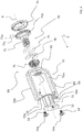
In FIGS. 1 and 2, with the numeric reference 10 there is an optical information acquisition device according to an embodiment. Hereinafter, reference shall be made to the device 10 referring to it also as a “reading device”.
The reading device 10 comprises an external case 11 within which an optical module 20 is housed that may contain all of the mechanical, optical and electronic components necessary for the reading of optical codes.
In particular, the optical module 20 comprises, in the specific example illustrated here, a pair of light sources 15 (FIG. 3) that are intended to illuminate an optical code to be read (not shown). The direction of emission of the beam of light emitted by the light sources 15 is indicated in the various figures with the letter E.
The optical module 20 further comprises an optical focusing group 21 with an optical axis (X) and an end flange 22 (FIGS. 3 and 4). In the specific example illustrated here, the optical focusing group 21 is interposed between the light sources 15.
The optical focusing group 21 collects the light diffused by the optical code illuminated by the light sources 15.
The optical module 20 also comprises an optical group for detecting the light beam focused by means of the optical focusing group 21. The optical detection group, which is not shown in the attached figures, comprises in particular an image sensor that lies in a plane perpendicular to the optical axis X and in optical alignment with the optical focusing group 21.
In the example illustrated here, the external case 11 includes a box-shaped body 211 and a mutually coupled cover or lid 311.
The box-shaped body 211 has a substantially parallelepiped form and houses therein the optical module 20.
The box-shaped body 211 has a face 212 (FIG. 1) that is open to allow for the insertion of the optical module 20. On the face opposite the box-shaped body 211 there is associated a frame 213 (FIG. 2) provided with a reading window 214 through which the light beam emitted by the light sources 15 exits and through which the light beam of diffused by the illuminated optical code enters.
Formed on the frame 213, on opposing sides with respect to the reading window 214, there are respective through holes 213 a for fixing the frame 213 onto the box-shaped body 211 by means of appropriate screws 213 b.
The box-shaped body 211 has, furthermore, on the inner surface of two opposing side walls 215 thereof, respective thickened portions 216 having a parallelepiped form wherein respective threaded holes 217 are obtained (FIG. 1).
The cover 311 is coupled to the box-shaped body 211 at the face 212 of the latter.
The cover 311 comprises a main body 312 wherefrom two opposing pairs of fins 313 a, 313 b protrude, which fit the box-shaped body 211 in such a way that each thickened portion 216 is interposed between a respective pair of fins 313 a, 313 b. The fins of each pair of fins 313 a, 313 b have planar facing surfaces in order to allow for the scrolling of the fins 313 a, 313 b upon the thickened portions 216 when the lid 311 is coupled to the box-shaped body 211.
The main body 312 comprises a front wall 315 (FIG. 1) whereupon a central through hole 316 and, on opposite sides to the central hole 316, respective through holes 317 aligned with the threaded holes 217 and intended to receive screws 318 for clamping the cover 311 on the box-shaped body 211 are formed.
The central hole 316 is coaxial to the optical axis X.
The reading device 10 further comprises a mask 411 housed within the box-shaped body 211. In FIG. 3 the mask 411 is not shown.
The mask 411 has openings to allow for the passage of the beam of light emitted by the light sources 15 and by the beam of light diffused by the illuminated optical code and is configured in such a way as to screen the aforesaid beams of light with respect to one another, thus preventing spurious radiation belonging to the beam of light emitted by the light sources 15 unintentionally being collected by the focusing device 21 before leaving the optical module 20.
As shown in FIGS. 1-3, the reading device 10 also comprises a printed circuit board or PCB 511 that, in the example illustrated here, is of the rigid-flexible type, and is particularly foldable in C form.
The printed circuit board 511 comprises a lower portion 512, an upper portion 513 and an intermediate portion 514 which is associated with the lower 512 and upper 513 portions by means of respective connectors 511 a configured in such a way as to carry electrical signals from one portion 512, 513, 514 to another.
The intermediate portion 514 has a central hole 515 which is coaxial to the optical axis X.
The printed circuit board 511 is also housed within the box-shaped body 211, with the intermediate portion 514 in abutment against the front wall 315 of the cover 311.
The lower portion 512 of the PCB 511 serves as a support plate for the optical module 20 within the box-shaped body 211.
The lower portion 512 of the PCB 511 comprises, at a center line portion thereof, a sliding seat 520 extending parallel to the optical axis X and whose function is described hereinafter (FIG. 3). In the embodiment illustrated and described herein, the sliding seat 520 is defined by a slot that stretches along a direction parallel to the optical axis X.
The lower portion 512 of the PCB 511 also comprises, on opposing sides with respect to the sliding seat 520, respective locking elements 521 of the optical module 20 on the lower portion 512 of the PCB 511.
The free end portions of the lower and upper portions 512 and 513 of the PCB 511 are associated with the mask 411.
The reading device 10 may further comprise a mechanical actuator 50 that is arranged for allowing the focusing distance to be adjusted. This mechanical actuator 50 will be described with particular reference to FIG. 4, where it is illustrated without the other components of the reading device 10 with which it cooperates.
The mechanical actuator 50 comprises a gripping member 51 of the optical focusing group 20. In particular, the gripping member 51 comprises a pair of arms 52 a, 52 b made as one piece with the connecting arm 53.
The arms 52 a, 52 b are parallel to the optical axis X and extend from symmetrically opposite sides with respect to the optical axis X.
The connecting arm 53 extends perpendicularly to the optical axis X and has a hole 56 that is coaxial to optical axis X.
The arm 52 a has a sliding projecting element 60 housed within the sliding seat 520 formed within the lower portion 512 of the PCB 511. Following an operation of the control element, the projecting element 60 slides within the sliding seat 520, guiding the axial movement of the gripping member 51, and therefore the optical focusing group 21.
As illustrated in FIGS. 1-3, the optical module 20 is arranged between the arms 52 a and 52 b, with the arm 52 a being interposed between the optical module 20, the lower portion 512 of the PCB 511 and the arm 52 b being interposed between the module 20 and the upper portion 513 of the PCB 511 and the connecting arm 53 being interposed between the optical module 20 and the intermediate portion 514 of the PCB 511.
The arms 52 a and 52 b are substantially C shaped and have, at the free end portions thereof, a fastening wall 55 at the end flange 22 of the optical focusing group 21. On the fastening wall 55 are formed threaded holes 55 a.
The fastening wall 55 extends perpendicularly to the optical axis X.
The end flange 22 is pushed in axial abutment against the fastening wall 55 by the head 54 a of a clamping screw 54 screwed into the threaded hole 55 a.
The offset end portion of the arms 52 a and 52 b is made as one piece with the connecting arm 53. The latter defines a wall for coupling the arms 52 a, 52 b (and therefore the gripping member 51) to a control member 70 that controls the axial movement of the gripping member 51, and therefore the optical focusing group 21.
Again, with reference to the FIG. 4, the control member 70 comprises an adjustment screw 71 that is coaxial to the optical axis X.
As illustrated in FIG. 1, the adjustment screw 71 is inserted into the through hole 316 formed in the front wall 315 of the cover 311, passes through the through hole 515 formed within the intermediate portion 514 of the PCB 511 until in engagement with a threaded insert 72 firmly housed within the hole 56 formed in the connecting arm 53 of the gripping member 51. Therefore the threaded insert 72 is also coaxial to the optical axis X.
The rotation of the adjustment screw 71 within the threaded insert 72 around the optical axis X may allow for the axial movement of the gripping member 51 with respect to the optical module 20.
In the example illustrated, the hole 56 has an internal thread and the threaded insert 72 has an external thread that mates with that of the hole 56 and that is opposite to that of the adjustment screw 71. In this way, it is possible to screw the threaded insert 72 in a stable way in the connecting arm 53 without the undesirable risk of unscrewing the threaded insert 72 during the axial movement of the gripping member 51 as a result of the engagement between the adjustment screw 71 and the threaded insert 72.
The adjustment screw 71 comprises a head 71 a arranged externally to the cover 311, and therefore externally to the external case 11.
The head 71 a acts as a control element for the rotation of the adjustment screw 71 around the optical axis X.
Mounted upon the head 71 a of the adjustment screw 71 there is a bezel 73 that is preferably graduated in such a way as to supply the user with a visual indication of the amount of rotation applied to the adjustment screw 71.
Arranged between the head 71 a of the adjustment screw 71 and the front wall 315 of the cover 311 there is, in a state of axial torsion, an elastic sealing gasket 75.
The adjustment screw 71 comprises a shank 71 b arranged internally to the external case 11 there being formed thereupon an annular groove 71 c that houses a circlip 76. This circlip 76 is in axial abutment against the front wall 315 of the cover 311 and avoids, together with the elastic gasket 75, any eventual undesired relative axial movement between the adjustment screw 71 and the external case 11.
In operation, in order to adjust the focusing distance of the reading device 10, the user turns, preferably by means of a screwdriver, the head 71 a of the screw 71, thus rotating the adjustment screw 71 within the threaded insert 72 and thereby producing an axial movement of the threaded insert 72 with respect to the adjustment screw 71. Given that the threaded insert is integral to the gripping member 51, the latter being integral to the optical focusing group 21, following rotation of the screw 71, axial movement occurs of the optical focusing group 21 by an amount proportional to the angle of rotation applied to the bezel 73.
The control member 70 described above can be used with any type of conventional optical module 20 having an optical focusing group 21 with an end flange 22.
Naturally, a person skilled in the art could make further changes and variations to the invention described above in order to satisfy specific and contingent application requirements, variations and modifications that nonetheless fall within the scope of protection as defined by the subsequent claims.

Claims (20)

The invention claimed is:
1. A device for the acquisition of optical information, comprising an external case and, within the external case:
an optical module including a housing having a first end and a second end and comprising an image sensor therein:
an optical focusing group in optical alignment with the optical module and configured to collect a light beam for the image sensor, the optical focusing group having an optical axis;
a mechanical actuator associated with the optical focusing group and configured to move the optical focusing group along the optical axis, wherein the mechanical actuator comprises:
a gripping member including;
a connecting arm positioned proximate the first end of the optical module and extending perpendicularly to the optical axis; and
a pair of extending arms connected to the connecting arm and extending parallel to the optical axis on opposite external sides of the optical module from the first end to the second end of the optical module; and
a control member coupled to the gripping member via a hole in the connecting arm that is coaxially aligned with the optical axis of the optical focusing group, the control member operable to:
rotate around the optical axis from the outside of the external case to axially move the optical focusing group relative to the image sensor via movement of the gripping member in a direction parallel to the optical axis.
2. A device according to claim 1, wherein the arms extend around the external sides of the optical module symmetrically with respect to the optical axis.
3. A device according to claim 1, wherein each of the arms is substantially C-shaped with a free end portion extending around the second end of the optical module, and a connected end portion extending around the first end portion to connect with the connecting; arm.
4. A device according to claim 3, wherein a fastening wall is held in axial abutment against an end flange of the optical focusing group by a clamping screw that is screwed into a threaded hole formed in the fastening wall and having a head in abutment against the end flange from opposite side with respect to the fastening wall.
5. A device according to claim 4, wherein the fastening walls extend substantially perpendicularly to the optical axis.
6. A device according to claim 3, wherein the pair of the arms and the connecting arm are made as one piece.
7. A device according to claim 1, wherein the external case comprises, therewithin, a PCB that supports the optical and module, wherein one of the arms is interposed between the optical module and the PCB.
8. A device according to claim 1, wherein the control member comprises:
a threaded insert integral the gripping member within the hole in the connecting arm and arranged coaxially the optical axis;
an adjustment screw engaged with the threaded insert; and
a control element configured to rotate the adjustment screw, wherein the control element is integral to the adjustment screw and is arranged externally to the external case.
9. A device according to claim 8, wherein the rotational control member is arranged coaxially to the optical axis.
10. A device according to claim 2, wherein each of the arms is substantially C-shaped with a free end portion extending around the second end of the optical module, and a connected end portion extending around the first end portion to connect with the connecting arm.
11. A device according to claim 7, wherein the control member comprises:
a threaded insert integral to the gripping member within the hole in the connecting arm and arranged coaxially to the optical axis;
an adjustment screw engaged with the threaded insert; and
a control element configured to rotate the adjustment screw, wherein the control element is integral to the adjustment screw and is arranged externally to the external case.
12. A device according to claim 8, further comprising a bezel mounted on a head of the adjustment screw.
13. A device according to claim 7, wherein:
one of the extending arms includes a sliding projecting element on an outer side thereof;
the PCB includes a sliding seat formed therein extending parallel to the optical axis; and
the sliding projection element fits into the sliding seat of the PCB to guide axial movement of the gripping member when activated by the control element.
14. A device according to claim 13, wherein the PCB further comprises at least one locking element to fix the optical module in place with the PCB.
15. A device according to claim 13, wherein the PCB is foldable in a C form with a hole in an intermediate portion that coaxially aligns with the hole in the connecting arm through which the adjustment screw passes to engage with the connecting arm of the gripping member.
16. A device according to claim 1, wherein the optical module includes light sources configured to illuminate an object with an optical code thereon.
17. A device according to claim 15, wherein the optical focusing group is interposed between the light sources.
18. A device according to claim 16, further comprising a reading window disposed perpendicular to the optical axis and in an exit path of the illumination of the light sources and an return path of the light beam from the optical code.
19. A device according to claim 3, wherein the optical focusing group includes an end flange in abutment with the free end portion of each arm of the gripping member.
20. A device according to claim 1, wherein the device is selected from the group consisting of a scanner, a vision sensor, and a smart camera.
US15/467,823 2016-03-25 2017-03-23 Device for acquiring optical information Active US10502925B2 (en)

Applications Claiming Priority (2)

Application Number Priority Date Filing Date Title
ITUA2016A002022A ITUA20162022A1 (en) 2016-03-25 2016-03-25 Optical information acquisition device
ITUA2016A002022 2016-03-25

Publications (2)

Publication Number Publication Date
US20170276901A1 US20170276901A1 (en) 2017-09-28
US10502925B2 true US10502925B2 (en) 2019-12-10

Family

ID=56369103

Family Applications (1)

Application Number Title Priority Date Filing Date
US15/467,823 Active US10502925B2 (en) 2016-03-25 2017-03-23 Device for acquiring optical information

Country Status (3)

Country Link
US (1) US10502925B2 (en)
DE (1) DE102017106378B4 (en)
IT (1) ITUA20162022A1 (en)

Cited By (2)

* Cited by examiner, † Cited by third party
Publication number Priority date Publication date Assignee Title
US20210286959A1 (en) * 2020-03-10 2021-09-16 Cognex Corporation Modular Vision System and Methods
US11665410B2 (en) 2020-03-10 2023-05-30 Cognex Corporation Modular vision systems and methods

Citations (12)

* Cited by examiner, † Cited by third party
Publication number Priority date Publication date Assignee Title
JPH04195010A (en) 1990-11-28 1992-07-15 Hitachi Ltd Lens driving mechanism
US5818023A (en) 1996-03-05 1998-10-06 Metanetics Corporation Portable ID card verification apparatus
GB2333852A (en) 1998-01-28 1999-08-04 Umax Data Systems Inc Camera lens focussing using a screw shaft
US5966248A (en) 1996-10-16 1999-10-12 Nikon Corporation Lens driving mechanism having an actuator
US6618211B2 (en) 1999-01-26 2003-09-09 Matsushita Electric Industrial Co., Ltd. Lens barrel free from influence of magnetic flux leakage
US20050094992A1 (en) 2003-10-06 2005-05-05 Pentax Corporation Lens barrel incorporating a one-way rotational transfer mechanism
US20060175411A1 (en) 2005-02-09 2006-08-10 Denso Wave Incorporated Optical information readout apparatus
US20110188136A1 (en) 2010-01-29 2011-08-04 Loreo Asia Ltd. Focusing mount
JP4775013B2 (en) 2006-02-07 2011-09-21 オムロン株式会社 Imaging device
JP2012123025A (en) 2010-12-06 2012-06-28 Sony Corp Electronic camera
US9007519B2 (en) 2010-03-12 2015-04-14 Omron Corporation Imaging device for measurement processing
US9182356B2 (en) 2011-11-22 2015-11-10 Keyence Corporation Image processing apparatus

Patent Citations (12)

* Cited by examiner, † Cited by third party
Publication number Priority date Publication date Assignee Title
JPH04195010A (en) 1990-11-28 1992-07-15 Hitachi Ltd Lens driving mechanism
US5818023A (en) 1996-03-05 1998-10-06 Metanetics Corporation Portable ID card verification apparatus
US5966248A (en) 1996-10-16 1999-10-12 Nikon Corporation Lens driving mechanism having an actuator
GB2333852A (en) 1998-01-28 1999-08-04 Umax Data Systems Inc Camera lens focussing using a screw shaft
US6618211B2 (en) 1999-01-26 2003-09-09 Matsushita Electric Industrial Co., Ltd. Lens barrel free from influence of magnetic flux leakage
US20050094992A1 (en) 2003-10-06 2005-05-05 Pentax Corporation Lens barrel incorporating a one-way rotational transfer mechanism
US20060175411A1 (en) 2005-02-09 2006-08-10 Denso Wave Incorporated Optical information readout apparatus
JP4775013B2 (en) 2006-02-07 2011-09-21 オムロン株式会社 Imaging device
US20110188136A1 (en) 2010-01-29 2011-08-04 Loreo Asia Ltd. Focusing mount
US9007519B2 (en) 2010-03-12 2015-04-14 Omron Corporation Imaging device for measurement processing
JP2012123025A (en) 2010-12-06 2012-06-28 Sony Corp Electronic camera
US9182356B2 (en) 2011-11-22 2015-11-10 Keyence Corporation Image processing apparatus

Non-Patent Citations (1)

* Cited by examiner, † Cited by third party
Title
Search Report and Opinion dated Mar. 25, 2016 for Italian Patent Application No. ITUA20162022, 8 pages.

Cited By (3)

* Cited by examiner, † Cited by third party
Publication number Priority date Publication date Assignee Title
US20210286959A1 (en) * 2020-03-10 2021-09-16 Cognex Corporation Modular Vision System and Methods
US11281868B2 (en) * 2020-03-10 2022-03-22 Cognex Corporation Modular vision system and methods
US11665410B2 (en) 2020-03-10 2023-05-30 Cognex Corporation Modular vision systems and methods

Also Published As

Publication number Publication date
DE102017106378A1 (en) 2017-09-28
DE102017106378B4 (en) 2020-08-20
ITUA20162022A1 (en) 2017-09-25
US20170276901A1 (en) 2017-09-28

Similar Documents

Publication Publication Date Title
US9076199B2 (en) System and method for determining and controlling focal distance in a vision system camera
US8803060B2 (en) Modular focus system alignment for image based readers
US6729546B2 (en) System for reading two-dimensional images using ambient and/or projected light
US5463213A (en) Code mark reader
EP2778734B1 (en) Lens assembly with integrated feedback loop for focus adjustment
US7762466B2 (en) Two position zoom lens assembly for an imaging-based bar code reader
US8289387B2 (en) Vision system, method for installing a vision system and method for manufacturing a vision system
US11574137B2 (en) Handheld ID-reading system with integrated illumination assembly
US10795060B2 (en) System and method for reduction of drift in a vision system variable lens
US12136015B2 (en) Alternative illuminator assembly and mobile imaging apparatus for improved direct part marking reading
US10502925B2 (en) Device for acquiring optical information
CN107944315B (en) Mobile imaging bar code scanner
US20060151608A1 (en) Targeting system for a portable image reader
CN110998591B (en) Optical information reading device and manufacturing method of optical information reading device
CN113311519B (en) System and method for reducing zoom lens drift in a vision system
US5589941A (en) Device for the measurement of a profile on a plane surface
WO2006088271A1 (en) Apparatus for stamp type barcode reader
KR100725647B1 (en) Stamped Barcode Reader
KR200388546Y1 (en) Apparatus for stamp type barcode reader

Legal Events

Date Code Title Description
AS Assignment

Owner name: DATALOGIC IP TECH S.R.L., ITALY

Free format text: ASSIGNMENT OF ASSIGNORS INTEREST;ASSIGNOR:MISTKAWI, JOSEPH;REEL/FRAME:041713/0363

Effective date: 20170323

STPP Information on status: patent application and granting procedure in general

Free format text: FINAL REJECTION MAILED

STPP Information on status: patent application and granting procedure in general

Free format text: DOCKETED NEW CASE - READY FOR EXAMINATION

STPP Information on status: patent application and granting procedure in general

Free format text: NOTICE OF ALLOWANCE MAILED -- APPLICATION RECEIVED IN OFFICE OF PUBLICATIONS

STPP Information on status: patent application and granting procedure in general

Free format text: PUBLICATIONS -- ISSUE FEE PAYMENT RECEIVED

STCF Information on status: patent grant

Free format text: PATENTED CASE

MAFP Maintenance fee payment

Free format text: PAYMENT OF MAINTENANCE FEE, 4TH YEAR, LARGE ENTITY (ORIGINAL EVENT CODE: M1551); ENTITY STATUS OF PATENT OWNER: LARGE ENTITY

Year of fee payment: 4