US10502067B2 - Dual-fed airfoil tip - Google Patents
Dual-fed airfoil tip Download PDFInfo
- Publication number
- US10502067B2 US10502067B2 US15/143,717 US201615143717A US10502067B2 US 10502067 B2 US10502067 B2 US 10502067B2 US 201615143717 A US201615143717 A US 201615143717A US 10502067 B2 US10502067 B2 US 10502067B2
- Authority
- US
- United States
- Prior art keywords
- cavity
- rib
- airfoil
- tip
- leading edge
- Prior art date
- Legal status (The legal status is an assumption and is not a legal conclusion. Google has not performed a legal analysis and makes no representation as to the accuracy of the status listed.)
- Active, expires
Links
Images


Classifications
-
- F—MECHANICAL ENGINEERING; LIGHTING; HEATING; WEAPONS; BLASTING
- F01—MACHINES OR ENGINES IN GENERAL; ENGINE PLANTS IN GENERAL; STEAM ENGINES
- F01D—NON-POSITIVE DISPLACEMENT MACHINES OR ENGINES, e.g. STEAM TURBINES
- F01D5/00—Blades; Blade-carrying members; Heating, heat-insulating, cooling or antivibration means on the blades or the members
- F01D5/12—Blades
- F01D5/14—Form or construction
- F01D5/18—Hollow blades, i.e. blades with cooling or heating channels or cavities; Heating, heat-insulating or cooling means on blades
- F01D5/187—Convection cooling
-
- F—MECHANICAL ENGINEERING; LIGHTING; HEATING; WEAPONS; BLASTING
- F01—MACHINES OR ENGINES IN GENERAL; ENGINE PLANTS IN GENERAL; STEAM ENGINES
- F01D—NON-POSITIVE DISPLACEMENT MACHINES OR ENGINES, e.g. STEAM TURBINES
- F01D25/00—Component parts, details, or accessories, not provided for in, or of interest apart from, other groups
- F01D25/08—Cooling; Heating; Heat-insulation
- F01D25/12—Cooling
-
- F—MECHANICAL ENGINEERING; LIGHTING; HEATING; WEAPONS; BLASTING
- F01—MACHINES OR ENGINES IN GENERAL; ENGINE PLANTS IN GENERAL; STEAM ENGINES
- F01D—NON-POSITIVE DISPLACEMENT MACHINES OR ENGINES, e.g. STEAM TURBINES
- F01D9/00—Stators
- F01D9/02—Nozzles; Nozzle boxes; Stator blades; Guide conduits, e.g. individual nozzles
-
- F—MECHANICAL ENGINEERING; LIGHTING; HEATING; WEAPONS; BLASTING
- F04—POSITIVE - DISPLACEMENT MACHINES FOR LIQUIDS; PUMPS FOR LIQUIDS OR ELASTIC FLUIDS
- F04D—NON-POSITIVE-DISPLACEMENT PUMPS
- F04D29/00—Details, component parts, or accessories
- F04D29/26—Rotors specially for elastic fluids
- F04D29/32—Rotors specially for elastic fluids for axial flow pumps
- F04D29/321—Rotors specially for elastic fluids for axial flow pumps for axial flow compressors
- F04D29/324—Blades
-
- F—MECHANICAL ENGINEERING; LIGHTING; HEATING; WEAPONS; BLASTING
- F04—POSITIVE - DISPLACEMENT MACHINES FOR LIQUIDS; PUMPS FOR LIQUIDS OR ELASTIC FLUIDS
- F04D—NON-POSITIVE-DISPLACEMENT PUMPS
- F04D29/00—Details, component parts, or accessories
- F04D29/40—Casings; Connections of working fluid
- F04D29/52—Casings; Connections of working fluid for axial pumps
- F04D29/54—Fluid-guiding means, e.g. diffusers
- F04D29/541—Specially adapted for elastic fluid pumps
- F04D29/542—Bladed diffusers
-
- F—MECHANICAL ENGINEERING; LIGHTING; HEATING; WEAPONS; BLASTING
- F04—POSITIVE - DISPLACEMENT MACHINES FOR LIQUIDS; PUMPS FOR LIQUIDS OR ELASTIC FLUIDS
- F04D—NON-POSITIVE-DISPLACEMENT PUMPS
- F04D29/00—Details, component parts, or accessories
- F04D29/58—Cooling; Heating; Diminishing heat transfer
- F04D29/582—Cooling; Heating; Diminishing heat transfer specially adapted for elastic fluid pumps
-
- F—MECHANICAL ENGINEERING; LIGHTING; HEATING; WEAPONS; BLASTING
- F05—INDEXING SCHEMES RELATING TO ENGINES OR PUMPS IN VARIOUS SUBCLASSES OF CLASSES F01-F04
- F05D—INDEXING SCHEME FOR ASPECTS RELATING TO NON-POSITIVE-DISPLACEMENT MACHINES OR ENGINES, GAS-TURBINES OR JET-PROPULSION PLANTS
- F05D2220/00—Application
- F05D2220/30—Application in turbines
- F05D2220/32—Application in turbines in gas turbines
-
- F—MECHANICAL ENGINEERING; LIGHTING; HEATING; WEAPONS; BLASTING
- F05—INDEXING SCHEMES RELATING TO ENGINES OR PUMPS IN VARIOUS SUBCLASSES OF CLASSES F01-F04
- F05D—INDEXING SCHEME FOR ASPECTS RELATING TO NON-POSITIVE-DISPLACEMENT MACHINES OR ENGINES, GAS-TURBINES OR JET-PROPULSION PLANTS
- F05D2250/00—Geometry
- F05D2250/10—Two-dimensional
- F05D2250/18—Two-dimensional patterned
- F05D2250/185—Two-dimensional patterned serpentine-like
-
- F—MECHANICAL ENGINEERING; LIGHTING; HEATING; WEAPONS; BLASTING
- F05—INDEXING SCHEMES RELATING TO ENGINES OR PUMPS IN VARIOUS SUBCLASSES OF CLASSES F01-F04
- F05D—INDEXING SCHEME FOR ASPECTS RELATING TO NON-POSITIVE-DISPLACEMENT MACHINES OR ENGINES, GAS-TURBINES OR JET-PROPULSION PLANTS
- F05D2260/00—Function
- F05D2260/20—Heat transfer, e.g. cooling
- F05D2260/202—Heat transfer, e.g. cooling by film cooling
-
- F—MECHANICAL ENGINEERING; LIGHTING; HEATING; WEAPONS; BLASTING
- F05—INDEXING SCHEMES RELATING TO ENGINES OR PUMPS IN VARIOUS SUBCLASSES OF CLASSES F01-F04
- F05D—INDEXING SCHEME FOR ASPECTS RELATING TO NON-POSITIVE-DISPLACEMENT MACHINES OR ENGINES, GAS-TURBINES OR JET-PROPULSION PLANTS
- F05D2260/00—Function
- F05D2260/20—Heat transfer, e.g. cooling
- F05D2260/221—Improvement of heat transfer
- F05D2260/2214—Improvement of heat transfer by increasing the heat transfer surface
- F05D2260/22141—Improvement of heat transfer by increasing the heat transfer surface using fins or ribs
-
- F—MECHANICAL ENGINEERING; LIGHTING; HEATING; WEAPONS; BLASTING
- F05—INDEXING SCHEMES RELATING TO ENGINES OR PUMPS IN VARIOUS SUBCLASSES OF CLASSES F01-F04
- F05D—INDEXING SCHEME FOR ASPECTS RELATING TO NON-POSITIVE-DISPLACEMENT MACHINES OR ENGINES, GAS-TURBINES OR JET-PROPULSION PLANTS
- F05D2260/00—Function
- F05D2260/60—Fluid transfer
- F05D2260/606—Bypassing the fluid
-
- Y—GENERAL TAGGING OF NEW TECHNOLOGICAL DEVELOPMENTS; GENERAL TAGGING OF CROSS-SECTIONAL TECHNOLOGIES SPANNING OVER SEVERAL SECTIONS OF THE IPC; TECHNICAL SUBJECTS COVERED BY FORMER USPC CROSS-REFERENCE ART COLLECTIONS [XRACs] AND DIGESTS
- Y02—TECHNOLOGIES OR APPLICATIONS FOR MITIGATION OR ADAPTATION AGAINST CLIMATE CHANGE
- Y02T—CLIMATE CHANGE MITIGATION TECHNOLOGIES RELATED TO TRANSPORTATION
- Y02T50/00—Aeronautics or air transport
- Y02T50/60—Efficient propulsion technologies, e.g. for aircraft
Definitions
- the subject matter disclosed herein generally relates to airflow in components of gas turbine engines and, more particularly, to dual-fed airfoil tips in components of gas turbine engines.
- Airfoils, and particularly airfoils of gas turbine engines may include internal flow passages to enable cooling of the airfoils. At various points within the airfoil cooling configurations, air may be bled from and/or between the internal flow passages.
- one way to improve efficiency is by increasing the pressure and temperature of the compressed and combusted air, from which the turbine extracts work.
- gaspath temperatures often exceed incipient melting temperatures of the constituent alloys of the airfoils.
- Complex internal cooling schemes may be configured to supply convective cooling and source film cooling.
- the airfoils may be produced by methods commonly used in the investment casting process of superalloys with alumina or silica ceramic cores, as well as, produced using additive manufacturing processes to directly fabricate the core by using Direct Metal Laser Sintering (SMLS) and/or Electron Beam Machining (EBM) processes.
- SMLS Direct Metal Laser Sintering
- EBM Electron Beam Machining
- the supply of the cooling air through cavities of the airfoils may be carefully designed so as to provide an efficient cooling configuration.
- the areas through which the cooling air must pass to serve its function do not necessarily proportionally increase. This presents an issue as there are deleterious effects associated with increasing the Mach number through the internal cavities of the airfoil.
- a common “pinch point” where a cavity Mach number may increase above an acceptable level is in the neck of an airfoil near the radial level of the platform, affecting typically leading-edge and trailing-edge feeds.
- a tip flag cavity underneath or within the proximity of the tip of an airfoil (e.g., a high pressure turbine blade), which is traditionally fed from a leading-edge feed cavity.
- the cooling air supply requirement for this cavity may increase the demand on the leading-edge feed, at times, to supply cooling air above an optimal level of flow.
- an airfoil of a gas turbine engine includes a leading edge extending in a radial direction, a tip extending in an axial direction from the leading edge, a first rib extending radially within the airfoil, the leading edge and the first rib defining a leading edge cavity within the airfoil, a second rib, the second rib and the first rib defining a serpentine cavity therein, a third rib extending axially within the tip, a flag tip cavity defined by the third rib, the leading edge, and the tip, the leading edge cavity fluidly connected to the flag tip cavity, and a bypass aperture formed between the first rib and the third rib, the bypass aperture configured to fluidly connect the serpentine cavity with the flag tip cavity.
- further embodiments of the airfoil may include a divider portion located proximate to the bypass aperture within the serpentine cavity and configured to aid in directing (i) a first portion of air from the serpentine cavity into the flag tip cavity and (ii) a second portion of air within the serpentine cavity.
- further embodiments of the airfoil may include that the divider portion is connected to the third rib.
- further embodiments of the airfoil may include that the divider portion extends a predetermined length into the serpentine cavity.
- further embodiments of the airfoil may include that the divider portion has a tapered tip extending into the serpentine cavity.
- further embodiments of the airfoil may include a trip strip configured to aid in airflow from the serpentine cavity to the flag tip cavity through the bypass aperture.
- further embodiments of the airfoil may include that the first rib includes a direction portion proximate to the bypass aperture.
- further embodiments of the airfoil may include that a width of the serpentine cavity between the first rib and the second rib is a first width and a width of the bypass aperture is a second width, wherein the second width is less than the first width.
- a gas turbine engine includes an airfoil having a leading edge extending in a radial direction, a tip extending in an axial direction form the leading edge, a first rib extending radially within the airfoil, the leading edge and the first rib defining a leading edge cavity within the airfoil, a second rib, the second rib and the first rib defining a serpentine cavity therein, a third rib extending axially within the tip, a flag tip cavity defined by the third rib, the leading edge, and the tip, the leading edge cavity fluidly connected to the flag tip cavity, and a bypass aperture formed between the first rib and the third rib, the bypass aperture configured to fluidly connect the serpentine cavity with the flag tip cavity.
- further embodiments of the gas turbine engine may include a divider portion located proximate to the bypass aperture within the serpentine cavity and configured to aid in directing (i) a first portion of air from the serpentine cavity into the flag tip cavity and (ii) a second portion of air within the serpentine cavity.
- further embodiments of the gas turbine engine may include that the divider portion is connected to the third rib.
- further embodiments of the gas turbine engine may include that the divider portion extends a predetermined length into the serpentine cavity.
- further embodiments of the gas turbine engine may include that the divider portion has a tapered tip extending into the serpentine cavity.
- further embodiments of the gas turbine engine may include that the divider portion is angled relative to a direction normal to the third rib.
- further embodiments of the gas turbine engine may include that the first rib includes a direction portion proximate to the bypass aperture.
- further embodiments of the gas turbine engine may include that a width of the serpentine cavity between the first rib and the second rib is a first width and a width of the bypass aperture is a second width, wherein the second width is less than the first width.
- a method of manufacturing an airfoil of a gas turbine engine includes forming an airfoil body having a leading edge cavity, a flag tip cavity, and a serpentine cavity, wherein the leading edge cavity is in fluid communication with the flag tip cavity and forming a bypass aperture to fluidly connect the serpentine cavity and the flag tip cavity.
- further embodiments of the method may include forming a divider portion located proximate to the bypass aperture within the serpentine cavity and configured to aid in directing (i) a first portion of air from the serpentine cavity into the flag tip cavity and (ii) a second portion of air within the serpentine cavity.
- further embodiments of the method may include that the airfoil is integrally formed by one of molding, casting, or additive manufacturing.
- further embodiments of the method may include forming a direction portion proximate to the bypass aperture on a rib between the leading edge cavity and the serpentine cavity.
- Technical effects of embodiments of the present disclosure include reduced Mach numbers in a leading-edge feed within an airfoil. Further technical effects may include reduced risk of flow disturbances and viscous losses while optimizing heat transfer, total-pressure, and static pressure requirements within internal cavities of the airfoil. Further technical effects include a dual-fed flag tip cavity of an airfoil.
- FIG. 1A is a schematic cross-sectional illustration of a gas turbine engine that may employ various embodiments disclosed herein;
- FIG. 1B is a schematic illustration of a turbine that may employ various embodiments disclosed herein;
- FIG. 2A is a cross-sectional schematic illustration of internal cavities of an airfoil in accordance with an embodiment of the present disclosure
- FIG. 2B is a schematic illustration of the airfoil of FIG. 2A indicating air flow within the internal cavities of the airfoil;
- FIG. 3 is a schematic illustration of the internal structure of an airfoil in accordance with an embodiment of the present disclosure
- FIG. 4A is a schematic illustration of an alternative configuration of an airfoil in accordance with the present disclosure showing example features
- FIG. 4B is a schematic illustration of another alternative configuration of an airfoil in accordance with the present disclosure showing example features
- FIG. 4C is a schematic illustration of another alternative configuration of an airfoil in accordance with the present disclosure showing example features
- FIG. 5 is a schematic illustration of an alternative configuration of an airfoil in accordance with the present disclosure.
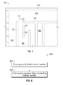
- FIG. 6 is a flow process of forming an airfoil for a gas turbine engine in accordance with an embodiment of the present disclosure.
- FIG. 1A schematically illustrates a gas turbine engine 20 .
- the exemplary gas turbine engine 20 is a two-spool turbofan engine that generally incorporates a fan section 22 , a compressor section 24 , a combustor section 26 , and a turbine section 28 .
- Alternative engines might include an augmenter section (not shown) among other systems for features.
- the fan section 22 drives air along a bypass flow path B, while the compressor section 24 drives air along a core flow path C for compression and communication into the combustor section 26 .
- Hot combustion gases generated in the combustor section 26 are expanded through the turbine section 28 .
- FIG. 1A schematically illustrates a gas turbine engine 20 .
- the exemplary gas turbine engine 20 is a two-spool turbofan engine that generally incorporates a fan section 22 , a compressor section 24 , a combustor section 26 , and a turbine section 28 .
- Alternative engines might include an augmenter section (not shown) among other systems for features.
- the gas turbine engine 20 generally includes a low speed spool 30 and a high speed spool 32 mounted for rotation about an engine centerline longitudinal axis A.
- the low speed spool 30 and the high speed spool 32 may be mounted relative to an engine static structure 33 via several bearing systems 31 . It should be understood that other bearing systems 31 may alternatively or additionally be provided.
- the low speed spool 30 generally includes an inner shaft 34 that interconnects a fan 36 , a low pressure compressor 38 and a low pressure turbine 39 .
- the inner shaft 34 can be connected to the fan 36 through a geared architecture 45 to drive the fan 36 at a lower speed than the low speed spool 30 .
- the high speed spool 32 includes an outer shaft 35 that interconnects a high pressure compressor 37 and a high pressure turbine 40 .
- the inner shaft 34 and the outer shaft 35 are supported at various axial locations by bearing systems 31 positioned within the engine static structure 33 .
- a combustor 42 is arranged between the high pressure compressor 37 and the high pressure turbine 40 .
- a mid-turbine frame 44 may be arranged generally between the high pressure turbine 40 and the low pressure turbine 39 .
- the mid-turbine frame 44 can support one or more bearing systems 31 of the turbine section 28 .
- the mid-turbine frame 44 may include one or more airfoils 46 that extend within the core flow path C.
- the inner shaft 34 and the outer shaft 35 are concentric and rotate via the bearing systems 31 about the engine centerline longitudinal axis A, which is co-linear with their longitudinal axes.
- the core airflow is compressed by the low pressure compressor 38 and the high pressure compressor 37 , is mixed with fuel and burned in the combustor 42 , and is then expanded over the high pressure turbine 40 and the low pressure turbine 39 .
- the high pressure turbine 40 and the low pressure turbine 39 rotationally drive the respective high speed spool 32 and the low speed spool 30 in response to the expansion.
- the pressure ratio of the low pressure turbine 39 can be pressure measured prior to the inlet of the low pressure turbine 39 as related to the pressure at the outlet of the low pressure turbine 39 and prior to an exhaust nozzle of the gas turbine engine 20 .
- the bypass ratio of the gas turbine engine 20 is greater than about ten (10:1)
- the fan diameter is significantly larger than that of the low pressure compressor 38
- the low pressure turbine 39 has a pressure ratio that is greater than about five (5:1). It should be understood, however, that the above parameters are only examples of one embodiment of a geared architecture engine and that the present disclosure is applicable to other gas turbine engines, including direct drive turbofans.
- TSFC Thrust Specific Fuel Consumption
- Fan Pressure Ratio is the pressure ratio across a blade of the fan section 22 without the use of a Fan Exit Guide Vane system.
- the low Fan Pressure Ratio according to one non-limiting embodiment of the example gas turbine engine 20 is less than 1.45.
- Low Corrected Fan Tip Speed is the actual fan tip speed divided by an industry standard temperature correction of [(Tram ° R)/(518.7° R)] 0.5 , where T represents the ambient temperature in degrees Rankine.
- the Low Corrected Fan Tip Speed according to one non-limiting embodiment of the example gas turbine engine 20 is less than about 1150 fps (351 m/s).
- Each of the compressor section 24 and the turbine section 28 may include alternating rows of rotor assemblies and vane assemblies (shown schematically) that carry airfoils that extend into the core flow path C.
- the rotor assemblies can carry a plurality of rotating blades 25
- each vane assembly can carry a plurality of vanes 27 that extend into the core flow path C.
- the blades 25 of the rotor assemblies create or extract energy (in the form of pressure) from the core airflow that is communicated through the gas turbine engine 20 along the core flow path C.
- the vanes 27 of the vane assemblies direct the core airflow to the blades 25 to either add or extract energy.
- Various components of a gas turbine engine 20 may be subjected to repetitive thermal cycling under widely ranging temperatures and pressures.
- the hardware of the turbine section 28 is particularly subjected to relatively extreme operating conditions. Therefore, some components may require internal cooling circuits for cooling the parts during engine operation.
- Example cooling circuits that include features such as airflow bleed ports are discussed below.
- FIG. 1B is a schematic view of a turbine section that may employ various embodiments disclosed herein.
- Turbine 100 includes a plurality of airfoils, including, for example, one or more blades 101 and vanes 102 .
- the airfoils 101 , 102 may be hollow bodies with internal cavities defining a number of channels or cavities, hereinafter airfoil cavities, formed therein and extending from an inner diameter 106 to an outer diameter 108 , or vice-versa.
- the airfoil cavities may be separated by partitions within the airfoils 101 , 102 that may extend either from the inner diameter 106 or the outer diameter 108 of the airfoil 101 , 102 .
- the partitions may extend for a portion of the length of the airfoil 101 , 102 , but may stop or end prior to forming a complete wall within the airfoil 101 , 102 .
- each of the airfoil cavities may be fluidly connected and form a fluid path within the respective airfoil 101 , 102 .
- the blades 101 and the vanes may include platforms 110 located proximal to the inner diameter thereof. Located below the platforms 110 may be airflow ports and/or bleed orifices that enable air to bleed from the internal cavities of the airfoils 101 , 102 .
- a root of the airfoil may connected to or be part of the platform 110 .
- FIGS. 2A and 2B views of an airfoil interior structure in accordance with a non-limiting embodiment of the present invention are shown.
- FIG. 2A is a cross-sectional view of airflow passages within an airfoil, such as a blade, having flow path structures in accordance with an embodiment of the present disclosure.
- FIG. 2B is another view of the airfoil of FIG. 2A , but showing the airflow path within the airfoil (without optional leading edge film cooling holes, flag tip film cooling holes, or trip strips).
- airflow passages as described herein may be applied to any type of airfoil or other component, such as blades, vanes, blade outer air seals, mid-turbine frames, turbine exhaust cases, etc.
- an airfoil 201 such as a turbine blade in a gas turbine engine, may define an airfoil body extending axially (with respect to an engine) from a leading edge 212 to a trailing edge 214 . Further, the airfoil body may extend radially from a root 216 at an inner diameter 206 to a tip 218 at an outer diameter 208 . The airfoil body may define one or more cavities therein that are configured to enable cooling of the airfoil 201 .
- a first flow path may be at the leading edge 212 of the airfoil and include a leading edge feed cavity 220 .
- Air may enter the leading edge cavity 220 at one or more leading feed cavity apertures 222 that are formed in the root 216 . The air may then flow from the root 216 toward the tip 218 . As the air flows through the leading edge cavity 220 a portion of the air may flow into one or more impingement cavities 224 positioned along the leading edge 212 of the airfoil 201 .
- the airflow path is shown by the arrows indicated in FIG. 2B .
- the leading edge cavity 220 is configured substantially vertical or radially extending within the airfoil 201 .
- Air from the leading edge cavity 220 may then turn and enter a flag tip cavity 226 .
- the flag tip cavity 226 may be a horizontally or axially oriented cooling air cavity configured at the tip 218 of the airfoil 201 .
- the flag tip cavity 226 may extend axially along the tip 218 of the airfoil 201 from the leading edge 212 to the trailing edge 214 .
- the airfoil 201 may also include one or more internal serpentine cavity 228 .
- the serpentine cavity 228 may be configured to provide cooling to an interior or central portion of the airfoil 201 that is between the leading edge cavity 220 and a trailing edge cavity 230 .
- a first partition or first rib 232 may separate the leading edge cavity 220 and the serpentine cavity 228 .
- a second partition or second rib 234 may separate the trailing edge cavity 230 and the serpentine cavity 228 .
- the serpentine cavity 228 may be separated from the flag tip cavity 226 by a third partition or third rib 236 .
- the serpentine cavity 228 may be configured in a serpentine manner that is configured to distribute air from one or more serpentine cavity apertures 238 through the serpentine cavity 228 as shown in FIG. 2B .
- the first rib 232 and the second rib 234 may extend radially within the airfoil 201 , e.g., with respect to an orientation as installed in an engine.
- a portion of the air within the serpentine cavity 228 may flow through a bypass aperture 240 located at an outer diameter of the serpentine cavity 228 and proximal to the leading edge cavity 220 and into the flag tip cavity 226 .
- the bypass aperture 240 may be formed in the axially extending third rib 236 , i.e., the bypass aperture 240 may be formed in the partition that separates the serpentine cavity 228 from the flag tip cavity 226 .
- the axially extending partition 236 may include a divider portion 242 that may extended radially inward from the axially extending partition 236 into the serpentine cavity 228 .
- the divider portion 242 may be configured to aid in the airflow separation at the bypass aperture 240 .
- An airfoil configured with a bypass aperture as shown may have a dual-fed flag tip cavity that may receive more air and air pressure than a traditional configuration that may have the flag tip cavity fed only from the leading edge cavity.
- air may enter the airfoil 201 through a trailing edge cavity aperture 244 .
- the air within the trailing edge cavity 230 may flow out of the tip trailing edge section of the airfoil 201 through one or more exit ports, as shown in FIG. 2B .
- higher pressure and colder cooling air supplied from serpentine cavity 228 can be mixed with the lower pressure, hotter fluid from the leading edge cavity 220 .
- the higher pressure air supplied to the flag tip cavity 226 back pressures the mass flow in the leading edge cavity 220 .
- the reduction in the velocity of the cooling flow in the leading edge cavity 220 enables an increase in pressure ratio across the leading edge cavity 220 which enables more cooling flow to be passed through operational leading edge showerhead holes 225 , providing increased convective and film cooling to the highest external heat flux location on the airfoil surface.
- the higher static pressure in the leading edge cavity 220 also ensures that minimum pressure ratio requirements are maintained across the leading showerhead holes 225 in order to prevent entrainment or ingestion of the hot external gas fluid into the leading edge showerhead holes 225 .
- the colder higher pressure cooling fluid flow that is provided from serpentine cavity 228 through bypass aperture 240 results in an increase in both the total and static pressure in the flag tip cavity 226 .
- the higher pressure in the flag tip cavity 226 enables more cooling flow to be exhausted through optional local tip film cooling holes 227 A and/or optional pressure side tip film cooling holes 227 B and a tip trailing edge section of airfoil 201 , thereby increasing the local convective heat transfer, film cooling, and thermal cooling effectiveness of tip 218 .
- the lower airfoil tip metal temperatures of tip 218 result in increased airfoil tip durability, capability, and improved retention of the blade airfoil tip clearance necessary for maintaining engine performance characteristics throughout the operating life of the propulsion system.
- trip strips 235 may be configured in one or more of the cavities 220 , 228 , 230 of the airfoil 201 . Further, although shown as located in a part of the serpentine cavity 228 , those of skill in the art will appreciate that the trip strips 235 can be located in various portions or subportions of any of the cavities 220 , 228 , 230 . As shown, the trip strips 235 have a chevron configuration but those of skill in the art will appreciate that other geometries for trip strips may be used without departing from the scope of the present disclosure. The trip strips 235 may be provided to increase internal convective heat transfer and direct airflow at the wall within the thermal boundary layer toward the bypass aperture 240 .
- FIG. 3 an enlarged schematic illustration of a bypass aperture in accordance with an embodiment of the present disclosure is shown.
- the configuration shown in FIG. 3 is of an airfoil similar to that shown and described with respect to FIGS. 2A and 2B .
- an airfoil 301 includes a leading edge cavity 320 , a serpentine cavity 328 , a trailing edge cavity 330 , and a flag tip cavity 326 .
- the cavities 320 , 326 , 328 , and 330 are defined in part, by a leading edge 312 , a first rib 332 , a second rib 334 , a third rib 336 , and a tip 318 .
- the leading edge cavity 320 is in fluid communication with the flag tip cavity 326 .
- the serpentine cavity 328 is in fluid communication with the flag tip cavity 326 through a bypass aperture 340 .
- the bypass aperture 340 is partially defined by a portion of the first rib 332 and a divider portion 342 .
- the divider portion 342 may be configured to better control the distribution of coolant flow between the serpentine cavity 328 and the flag tip cavity 326 .
- the curvature of divider portion 342 allows the coolant flow from the serpentine cavity 328 to diffuse as it is mixed with the coolant flow from the leading edge cavity 320 .
- Air flowing within the serpentine cavity 328 along the first rib 332 may be defined in part by a first width W 1 of the serpentine cavity 328 .
- the first width W 1 may be a width or distance between the first rib 332 and a portion of the second rib 334 near the bypass aperture 340 .
- the air within the serpentine cavity 328 may then split at the bypass aperture 340 with a first portion of air flowing through the bypass aperture 340 into the flag tip cavity 326 and a second portion of air flowing within the serpentine cavity 328 .
- a volume of the first portion of air may be defined in part by a second width W 2 that is a distance between the first rib 332 and the divider portion 342 .
- a volume of the second portion of air may be defined in part by a third width W 3 that is a distance between the divider portion 342 and a part of the second rib 334 .
- the first portion of air may flow from the serpentine cavity 328 into the flag tip cavity 326 through the bypass aperture and the second portion of air may continue flow within the serpentine cavity 328 .
- the second portion of air may turn within the serpentine cavity 328 and enter another part of the serpentine cavity 328 defined in part by two portions of the second rib 334 and having a fourth width W 4 .
- the third width W 3 and the fourth width W 4 may be equal.
- the second width W 2 and the third width W 3 may be equal.
- the divider portion 342 may be an extension of the third (or axially extending) rib 336 located close to the tip of the airfoil 301 .
- the third rib 336 may have a thickness T 1 .
- the divider portion 342 may have the same thickness as the third rib 336 .
- the divider portion 342 may have a length L 1 and extend into the serpentine cavity 328 .
- the second width W 2 may be less than the first width W 2 .
- first width W 1 may be equal to the second width W 1 , the third width W 3 , and the thickness T 1 .
- FIG. 4A an alternative configuration of an airfoil is shown having example features that may be employed in one or more embodiments of the present disclosure.
- the structure of the airfoil 400 is substantially similar to that shown in FIG. 3 , with the airfoil 400 including a leading edge cavity 420 that is configured to supply air to a flag tip cavity 426 at a tip 418 of the airfoil 400 .
- a bypass aperture 440 may be formed between a first rib 432 and portion of a third or axially extending rib 436 . As shown, the bypass aperture 440 may be defined in part by a directional portion 444 of the first rib 432 .
- the directional portion 444 may be an end of the first rib 432 having a curvature or other structure, geometry, and/or shape that is configured to aid in directing air from the serpentine cavity 428 into the flag tip cavity 426 .
- Such structure, geometry, and/or shape may be selected to provide an axial velocity component to a coolant flow entering the flag tip cavity 426 .
- the direction portion may be angled away from the bypass aperture 440 .
- a direction portion 445 of the first rib 432 is shown.
- the first rib 432 may have a canted end or tip that is proximate the bypass aperture 440 (e.g., direction portions 444 , 445 , etc.).
- the canted rib allows for velocity of flow through the bypass aperture 440 to diffuse to reduce mixing loss from the leading edge cavity 420 .
- the directional component of the flow emanating from the serpentine cavity 428 through the bypass aperture 440 may be aligned in the axial direction as it is combined with the coolant flow from the leading edge cavity 420 .
- the improved alignment between the two flow streams reduces the momentum mixing and pressure loss that would be incurred as the two flows are mixed in flag tip cavity 426
- the coolant flow exiting bypass aperture 440 from the serpentine cavity 428 has sufficiently greater velocity with respect to the coolant flow from the leading edge cooling cavity 420 .
- the mixed cooling flow in the flag tip cavity 426 is accelerated due to jet pump characteristics associated with the high velocity cooling flow exiting through the bypass aperture 440 supplied from the serpentine cavity 428 .
- the acceleration of the cooling flow increases the internal convective heat transfer improving the local thermal cooling effectiveness adjacent to the flag tip cavity 426 .
- a divider portion 442 of the third rib 436 may be angled relative to a direction normal to the third rib 436 .
- the angle of the divider portion 442 may be configured to aid in air flow both within the serpentine cavity 428 and through the bypass aperture 440 .
- the divider portion 442 of the third rib 436 and the direction portion 444 of the first rib 432 may be configured parallel to each other or otherwise angled and configured with respect to each other.
- the divider portion 442 may include a tapered tip 446 .
- the tapered tip 446 may be configured to aid in air flow both within the serpentine cavity 428 and through the bypass aperture 440 .
- the tapering of the tapered tip 446 may form a point or defined point, edge, or end.
- the tapered tip 446 may be rounded, as shown, for example, in FIG. 4A .
- trip strips 437 are shown.
- the trip strips 437 of FIG. 4A are skewed and segmented (as compared to the chevron trip strips 235 of FIG. 2A ).
- a particular configuration e.g., geometry, length, skew angle, etc.
- those of skill in the art will appreciate that other orientations and/or configurations can be used without departing from the scope of the present disclosure.
- the skew angle of the trip strips 437 can be reversed.
- Various configurations and/or orientations of trip strips can be incorporated in various embodiments described herein, and may be configured based on, for example, flow and pressure loss requirements of the particular airfoil.
- a leading edge cavity 420 B includes a convective leading edge feature 421 B, such as a plurality of trip strips and/or film cooling. Further, as shown, a convective flag tip feature 429 B is shown.
- the convective flag tip feature 429 B may be, for example, trip strips and/or film cooling, as known in the art.
- a leading edge cavity 420 C includes a convective leading edge feature 421 C, such as a plurality of trip strips and/or film cooling.
- a convective flag tip feature 429 C is shown.
- the convective flag tip feature 429 C may be, for example, trip strips and/or film cooling, as known in the art.
- a bypass aperture 440 C is formed between a first rib and a portion (e.g., divider portion 442 C) of a third or axially extending rib 436 C.
- the axially extending (or third) rib 436 C is not parallel with a tip 418 C, but rather is angled with respect to the tip 418 C.
- the airfoil 401 C includes a convective leading edge with tip film cooling and convective tip flag cooling (i.e., there is no tip film cooling).
- FIG. 5 an alternative configuration of a bypass aperture in accordance with an embodiment of the present disclosure is shown.
- the structure of the airfoil 500 is substantially similar to that shown in FIG. 3 , with the airfoil 500 including a leading edge cavity 520 that is configured to supply air to a flag tip cavity 526 at a tip 518 of the airfoil 500 .
- a bypass aperture 540 may be formed between a first rib 532 and portion of a third or axially extending rib 536 .
- the third or axially extending rib 536 does not include a divider portion as in the prior embodiments. That is, the bypass aperture 540 may be defined by a space between an end of the first rib 532 and an end of the third or axially extending rib 536 .
- the trip strips 548 are located within a portion of the serpentine cavity 528 near the bypass aperture 540 .
- the optional trip strips may be heat transfer augmentation device, which may be located in any of the passages 520 , 526 , 528 and/or within the bypass aperture 540 .
- the size, pitch, and/or configuration of the trip strips can be configured in conjunction with the various widths and/or dimensions of the cavities and/or ribs such that the flow split enabled by the bypass aperture 540 may be optimized.
- a triangular divider portion may be used.
- the divider portion may not be physically connected to the third or axially extending rib, but rather may be a discrete feature within the serpentine cavity of the airfoil.
- an end of the first rib may form a structure that is configured to aid in the air flow within the airfoil.
- various features and/or structures shown and described above in the example embodiments e.g., FIGS. 2A-5
- an airfoil may be formed with internal cavities, including a leading edge cavity, a flag tip cavity, and a serpentine cavity.
- a bypass aperture is formed to fluidly connect the serpentine cavity with the flag tip cavity such that the flag tip cavity is provided with air and/or airflow from both the leading edge cavity and the serpentine cavity.
- the steps of the flow process 900 may be performed simultaneously and/or nearly simultaneously, or as separate discrete steps.
- blocks 902 and 904 may be performed simultaneously in a casting, molding, or additive manufacturing process.
- embodiments described herein provide an airfoil having fluidly connected internal cavities such that the airflow may be increased into a flag tip cavity at a tip of the airfoil.
- bypass apertures as provided herein may enable a reduction in Mach number in leading edge cavity feed into the flag tip cavity, thereby reducing a risk of flow disturbances and viscous losses while optimizing heat transfer in airfoil and improve pressure availability downstream within the flag tip cavity.
- embodiments provided herein my enable improved back-flow margins for cooling holes fed by the leading edge cavity, which may be related to an increased pressure in the leading edge because the air within the flag tip cavity is supplemented and supplied in part from the serpentine cavity.
- embodiments provided here may increase casting producibility of both the serpentine cavity and the flag tip cavity by directly and fluidly tying the two cavities together.
- embodiments provided herein may reduce casting cost by eliminating a tip rod from a serpentine up-pass.
Landscapes
- Engineering & Computer Science (AREA)
- Mechanical Engineering (AREA)
- General Engineering & Computer Science (AREA)
- Physics & Mathematics (AREA)
- Thermal Sciences (AREA)
- Turbine Rotor Nozzle Sealing (AREA)
Abstract
Description
Claims (15)
Priority Applications (2)
| Application Number | Priority Date | Filing Date | Title |
|---|---|---|---|
| US15/143,717 US10502067B2 (en) | 2016-01-22 | 2016-05-02 | Dual-fed airfoil tip |
| EP17152351.7A EP3196414B1 (en) | 2016-01-22 | 2017-01-20 | Dual-fed airfoil tip |
Applications Claiming Priority (2)
| Application Number | Priority Date | Filing Date | Title |
|---|---|---|---|
| US201662281954P | 2016-01-22 | 2016-01-22 | |
| US15/143,717 US10502067B2 (en) | 2016-01-22 | 2016-05-02 | Dual-fed airfoil tip |
Publications (2)
| Publication Number | Publication Date |
|---|---|
| US20170211396A1 US20170211396A1 (en) | 2017-07-27 |
| US10502067B2 true US10502067B2 (en) | 2019-12-10 |
Family
ID=57868084
Family Applications (1)
| Application Number | Title | Priority Date | Filing Date |
|---|---|---|---|
| US15/143,717 Active 2037-12-04 US10502067B2 (en) | 2016-01-22 | 2016-05-02 | Dual-fed airfoil tip |
Country Status (2)
| Country | Link |
|---|---|
| US (1) | US10502067B2 (en) |
| EP (1) | EP3196414B1 (en) |
Cited By (3)
| Publication number | Priority date | Publication date | Assignee | Title |
|---|---|---|---|---|
| US20200291789A1 (en) * | 2019-03-12 | 2020-09-17 | United Technologies Corporation | Airfoils having tapered tip flag cavity and cores for forming the same |
| US12467368B1 (en) | 2025-01-07 | 2025-11-11 | Honeywell International Inc. | Turbine blade double tip flag cooling system |
| US12553350B2 (en) | 2024-02-20 | 2026-02-17 | Rtx Corporation | Combined tip flag blade core |
Families Citing this family (7)
| Publication number | Priority date | Publication date | Assignee | Title |
|---|---|---|---|---|
| US10519782B2 (en) * | 2017-06-04 | 2019-12-31 | United Technologies Corporation | Airfoil having serpentine core resupply flow control |
| US10753207B2 (en) * | 2017-07-13 | 2020-08-25 | General Electric Company | Airfoil with tip rail cooling |
| US10655476B2 (en) * | 2017-12-14 | 2020-05-19 | Honeywell International Inc. | Gas turbine engines with airfoils having improved dust tolerance |
| US10458253B2 (en) | 2018-01-08 | 2019-10-29 | United Technologies Corporation | Gas turbine engine components having internal hybrid cooling cavities |
| WO2020167598A1 (en) * | 2019-02-08 | 2020-08-20 | United Technologies Corporation | Turbine blade trailing edge cooling feed |
| CN112383252B (en) * | 2020-10-30 | 2022-05-06 | 华北电力科学研究院有限责任公司 | Method and device per unit for excitation control system of doubly-fed generator set |
| US12006836B2 (en) * | 2021-07-02 | 2024-06-11 | Rtx Corporation | Cooling arrangement for gas turbine engine component |
Citations (8)
| Publication number | Priority date | Publication date | Assignee | Title |
|---|---|---|---|---|
| WO1994012766A1 (en) | 1992-11-30 | 1994-06-09 | United Technologies Corporation | Coolable airfoil structure |
| EP1510653A2 (en) | 2003-07-29 | 2005-03-02 | Siemens Aktiengesellschaft | Cooled turbine blade |
| US20060153678A1 (en) * | 2005-01-07 | 2006-07-13 | Siemens Westinghouse Power Corp. | Cooling system with internal flow guide within a turbine blade of a turbine engine |
| US20070041835A1 (en) * | 2005-08-16 | 2007-02-22 | Charbonneau Robert A | Turbine blade including revised trailing edge cooling |
| US20100226789A1 (en) | 2009-03-04 | 2010-09-09 | Siemens Energy, Inc. | Turbine blade dual channel cooling system |
| WO2011161188A1 (en) | 2010-06-23 | 2011-12-29 | Siemens Aktiengesellschaft | Gas turbine blade |
| US20130280080A1 (en) | 2012-04-23 | 2013-10-24 | Jeffrey R. Levine | Gas turbine engine airfoil with dirt purge feature and core for making same |
| US9546554B2 (en) * | 2012-09-27 | 2017-01-17 | Honeywell International Inc. | Gas turbine engine components with blade tip cooling |
-
2016
- 2016-05-02 US US15/143,717 patent/US10502067B2/en active Active
-
2017
- 2017-01-20 EP EP17152351.7A patent/EP3196414B1/en active Active
Patent Citations (8)
| Publication number | Priority date | Publication date | Assignee | Title |
|---|---|---|---|---|
| WO1994012766A1 (en) | 1992-11-30 | 1994-06-09 | United Technologies Corporation | Coolable airfoil structure |
| EP1510653A2 (en) | 2003-07-29 | 2005-03-02 | Siemens Aktiengesellschaft | Cooled turbine blade |
| US20060153678A1 (en) * | 2005-01-07 | 2006-07-13 | Siemens Westinghouse Power Corp. | Cooling system with internal flow guide within a turbine blade of a turbine engine |
| US20070041835A1 (en) * | 2005-08-16 | 2007-02-22 | Charbonneau Robert A | Turbine blade including revised trailing edge cooling |
| US20100226789A1 (en) | 2009-03-04 | 2010-09-09 | Siemens Energy, Inc. | Turbine blade dual channel cooling system |
| WO2011161188A1 (en) | 2010-06-23 | 2011-12-29 | Siemens Aktiengesellschaft | Gas turbine blade |
| US20130280080A1 (en) | 2012-04-23 | 2013-10-24 | Jeffrey R. Levine | Gas turbine engine airfoil with dirt purge feature and core for making same |
| US9546554B2 (en) * | 2012-09-27 | 2017-01-17 | Honeywell International Inc. | Gas turbine engine components with blade tip cooling |
Non-Patent Citations (1)
| Title |
|---|
| European Search Report, European Application No. 17152351.7, dated May 19, 2017, European Patent Office; European Search Report 7 pages. |
Cited By (4)
| Publication number | Priority date | Publication date | Assignee | Title |
|---|---|---|---|---|
| US20200291789A1 (en) * | 2019-03-12 | 2020-09-17 | United Technologies Corporation | Airfoils having tapered tip flag cavity and cores for forming the same |
| US10914178B2 (en) * | 2019-03-12 | 2021-02-09 | Raytheon Technologies Corporation | Airfoils having tapered tip flag cavity and cores for forming the same |
| US12553350B2 (en) | 2024-02-20 | 2026-02-17 | Rtx Corporation | Combined tip flag blade core |
| US12467368B1 (en) | 2025-01-07 | 2025-11-11 | Honeywell International Inc. | Turbine blade double tip flag cooling system |
Also Published As
| Publication number | Publication date |
|---|---|
| EP3196414A1 (en) | 2017-07-26 |
| EP3196414B1 (en) | 2018-11-28 |
| US20170211396A1 (en) | 2017-07-27 |
Similar Documents
| Publication | Publication Date | Title |
|---|---|---|
| US10502067B2 (en) | Dual-fed airfoil tip | |
| US11148191B2 (en) | Core arrangement for turbine engine component | |
| US10808546B2 (en) | Gas turbine engine airfoil trailing edge suction side cooling | |
| US20190085705A1 (en) | Component for a turbine engine with a film-hole | |
| US10337332B2 (en) | Airfoil having pedestals in trailing edge cavity | |
| US20200024951A1 (en) | Component for a turbine engine with a cooling hole | |
| US10465542B2 (en) | Gas turbine engine turbine vane baffle and serpentine cooling passage | |
| EP3034793B1 (en) | Gas turbine engine component with increased cooling capacity | |
| US20180051566A1 (en) | Airfoil for a turbine engine with a porous tip | |
| US20170268346A1 (en) | Component for a turbine engine with a film hole | |
| US20190071977A1 (en) | Component for a turbine engine with a cooling hole | |
| EP3112596A1 (en) | Gas turbine engine airfoil with bi-axial skin cooling passage and corresponding gas turbine engine | |
| US10760431B2 (en) | Component for a turbine engine with a cooling hole | |
| US20160003152A1 (en) | Gas turbine engine multi-vaned stator cooling configuration | |
| EP3453831B1 (en) | Airfoil having contoured pedestals | |
| US20200024967A1 (en) | Airfoil having angled trailing edge slots | |
| US20180051571A1 (en) | Airfoil for a turbine engine with porous rib | |
| US20160251968A1 (en) | Gas turbine engine airfoil cooling configuration with pressure gradient separators | |
| EP2977557B1 (en) | Cooled airfoil structure and corresponding cooling method | |
| US10655496B2 (en) | Platform flow turning elements for gas turbine engine components | |
| US20190169995A1 (en) | Double wall turbine gas turbine engine blade cooling configuration |
Legal Events
| Date | Code | Title | Description |
|---|---|---|---|
| AS | Assignment |
Owner name: UNITED TECHNOLOGIES CORPORATION, CONNECTICUT Free format text: ASSIGNMENT OF ASSIGNORS INTEREST;ASSIGNORS:MONGILLO, DOMINIC J.;JARIWALA, PARTH;TELLER, BRET M.;AND OTHERS;SIGNING DATES FROM 20160426 TO 20160429;REEL/FRAME:038433/0040 |
|
| STPP | Information on status: patent application and granting procedure in general |
Free format text: FINAL REJECTION MAILED |
|
| STPP | Information on status: patent application and granting procedure in general |
Free format text: DOCKETED NEW CASE - READY FOR EXAMINATION |
|
| STPP | Information on status: patent application and granting procedure in general |
Free format text: NOTICE OF ALLOWANCE MAILED -- APPLICATION RECEIVED IN OFFICE OF PUBLICATIONS |
|
| STPP | Information on status: patent application and granting procedure in general |
Free format text: AWAITING TC RESP., ISSUE FEE NOT PAID |
|
| STPP | Information on status: patent application and granting procedure in general |
Free format text: NOTICE OF ALLOWANCE MAILED -- APPLICATION RECEIVED IN OFFICE OF PUBLICATIONS |
|
| STCF | Information on status: patent grant |
Free format text: PATENTED CASE |
|
| AS | Assignment |
Owner name: RAYTHEON TECHNOLOGIES CORPORATION, MASSACHUSETTS Free format text: CHANGE OF NAME;ASSIGNOR:UNITED TECHNOLOGIES CORPORATION;REEL/FRAME:054062/0001 Effective date: 20200403 |
|
| AS | Assignment |
Owner name: RAYTHEON TECHNOLOGIES CORPORATION, CONNECTICUT Free format text: CORRECTIVE ASSIGNMENT TO CORRECT THE AND REMOVE PATENT APPLICATION NUMBER 11886281 AND ADD PATENT APPLICATION NUMBER 14846874. TO CORRECT THE RECEIVING PARTY ADDRESS PREVIOUSLY RECORDED AT REEL: 054062 FRAME: 0001. ASSIGNOR(S) HEREBY CONFIRMS THE CHANGE OF ADDRESS;ASSIGNOR:UNITED TECHNOLOGIES CORPORATION;REEL/FRAME:055659/0001 Effective date: 20200403 |
|
| MAFP | Maintenance fee payment |
Free format text: PAYMENT OF MAINTENANCE FEE, 4TH YEAR, LARGE ENTITY (ORIGINAL EVENT CODE: M1551); ENTITY STATUS OF PATENT OWNER: LARGE ENTITY Year of fee payment: 4 |
|
| AS | Assignment |
Owner name: RTX CORPORATION, CONNECTICUT Free format text: CHANGE OF NAME;ASSIGNOR:RAYTHEON TECHNOLOGIES CORPORATION;REEL/FRAME:064714/0001 Effective date: 20230714 |