US1049852A - Headlight-shifter. - Google Patents
Headlight-shifter. Download PDFInfo
- Publication number
- US1049852A US1049852A US68658612A US1912686586A US1049852A US 1049852 A US1049852 A US 1049852A US 68658612 A US68658612 A US 68658612A US 1912686586 A US1912686586 A US 1912686586A US 1049852 A US1049852 A US 1049852A
- Authority
- US
- United States
- Prior art keywords
- pendulum
- platform
- rack
- teeth
- notch
- Prior art date
- Legal status (The legal status is an assumption and is not a legal conclusion. Google has not performed a legal analysis and makes no representation as to the accuracy of the status listed.)
- Expired - Lifetime
Links
- 230000003137 locomotive effect Effects 0.000 description 5
- 238000010276 construction Methods 0.000 description 2
- 230000005484 gravity Effects 0.000 description 2
- 239000000779 smoke Substances 0.000 description 2
- 208000027418 Wounds and injury Diseases 0.000 description 1
- 230000006378 damage Effects 0.000 description 1
- 230000003467 diminishing effect Effects 0.000 description 1
- 208000014674 injury Diseases 0.000 description 1
- 230000002787 reinforcement Effects 0.000 description 1
Images
Classifications
-
- B—PERFORMING OPERATIONS; TRANSPORTING
- B60—VEHICLES IN GENERAL
- B60Q—ARRANGEMENT OF SIGNALLING OR LIGHTING DEVICES, THE MOUNTING OR SUPPORTING THEREOF OR CIRCUITS THEREFOR, FOR VEHICLES IN GENERAL
- B60Q1/00—Arrangement of optical signalling or lighting devices, the mounting or supporting thereof or circuits therefor
- B60Q1/02—Arrangement of optical signalling or lighting devices, the mounting or supporting thereof or circuits therefor the devices being primarily intended to illuminate the way ahead or to illuminate other areas of way or environments
- B60Q1/04—Arrangement of optical signalling or lighting devices, the mounting or supporting thereof or circuits therefor the devices being primarily intended to illuminate the way ahead or to illuminate other areas of way or environments the devices being headlights
- B60Q1/06—Arrangement of optical signalling or lighting devices, the mounting or supporting thereof or circuits therefor the devices being primarily intended to illuminate the way ahead or to illuminate other areas of way or environments the devices being headlights adjustable, e.g. remotely-controlled from inside vehicle
- B60Q1/068—Arrangement of optical signalling or lighting devices, the mounting or supporting thereof or circuits therefor the devices being primarily intended to illuminate the way ahead or to illuminate other areas of way or environments the devices being headlights adjustable, e.g. remotely-controlled from inside vehicle by mechanical means
Definitions
- MOSES W. HARVEY OF CLEAR CREEK, WEST VIRGINIA, ASSIGNOR; OF ONE-HALF TO HENRY F. WEST, OF PAINTSVILLE, WEST VIRGINIA.
- Patented J an. 7, 1913.
- the device forming the subject-matter of this application is adapted to be mounted upon a locomotive engine, to carry the headlight thereof, the device being so constructed that when the locomotive rounds a curve, a
- pendulum will swing toward the inside of the curve, owing to the elevation of the outer rail, the headlight of the locomotive being thereby swung laterally, to follow the curve.
- the objects of'the invention are to provide a device of this type in which the center of gravity of the pendulum may be shifted readily, to provide resilient means for limiting the movement of the pendulum; to provide positive means whereby the swinging movement of the member which carries the lamp, may be adjusted'to take place within a predetermined are only; to provide novel means for. protecting the teeth of the member which carries the lamp; and to improve generally, and to increase the efliciency of, devices of the type to which the present invention appertains.
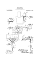
- FIG. 1 is a fragmental side elevation of a locomotive engine, equipped with the device of my invention
- Fig. 2 shows the invention in rear elevation
- Fig. 3 is a section on the line CD of Fig. 2
- Fig. 4 is a top plan
- Fig. 5 is a fragmental section upon the line A-B of Fig. 4
- Fig. 6 is a detail perspective of the platform.
- a platform 1 having in its rear edge, a notch 2.
- a tongue 3 is fixed to the base 4 of the notch 2, and depends below theplane of the platform 1.
- the invention further includes a segmental rack 5, across which extends a pendulum 6, the upper end of the pendulum 6 being disposed in close relation to the teeth of the rack, the pedulum and the rack being fastened together by means of securing elements 7. Owing ,to the fact that the pendulum 6 extends entirely across the rack 5, into close relation to the teeth 8 of the rack, the upper portion of the pendulum 6 serves to reinforce and to strengthen the rack.- A pivot element 9 extends through the pendulum 6 and through the rack 5, into engagement with the tongue 3, and thus the rack and the pendulum are supported for vertical swinging movement, adjacent the rear of the platform 1.
- the rack 5 and the upper end of the pendulum 6 are adapted to move in the notch 2, within the contour of the platform 1.
- the platform 1 may be placed in close relation to the forward end face of the smoke box 24 of the boiler, and be supported upon the usual brackets 25, without jeopardizing the operation of the invention, through engagement between the upper end of the pendulum 6 and the smoke box 24 of the engine.
- retractile springs '12 preferably of helical configuration, are secured at their upper ends tothe platform 1, the springs 12 converging downwardly into union with the pendulum 6, below its pivotal mounting 9.
- a washer 15 superposed upon the platform 1 is a washer 15, and upon the washer 15 rests a toothed member 14, the washer constituting a means for spacing the member 14 apart from the upper surface of the platform 1.
- a pivot element 16 is extended through the washer 15 and through the member 14, whereby the latter is rotatably connected with the platform 1.
- the upper surface of the member 14 carries means for holding the lamp 26, the lamp-holding means being of any desired form, and being indicated at 17.
- the member 14 is formed in it periphery, and adjacent its rear edge, with anotch 18, from the base 19 of'which, teeth 20 outstand, the teeth 20 being adapted to mesh int-o the teeth 8 of the rack 5. It is to be noted that, owing to the fact'that the teeth 20 project from the base 19 of the notch 18, the major portion of the periphery of the member 14 outstands beyond the outer ends of the teeth 20, and thus the teeth are protected against injury.
- the member 14 is equipped in its periphery, and adjacent its forward edge, with a notch 21,the ends of which define shoulders 22. Threaded into the platform 1, is a screw 23. This screw 23 is manipulated, so that its upper end will be located between the shoulders 22, to engage the shoulders 22 successively, when the member 14 is rotating; or, if desired, thescrew 23 may be retracted, so that the member 14 may rotate freely, as though the screw 23 were not included in the structure.
- the screw 23 may be. moved by the engagement between the screw 23 and the shoulders 22.
- the notch 2l may be of any desired extent, thus adjusting the space between the shoulders 22, and thereby enlarging or diminishing 'the extent of the largest are through which the lamp 26 can swing.
- the operation of the device is as follows: When the locomotive engine rounds a curve in the track, the weight 11, owing to the elevation of the outside rail, will swing the pendulum 6, the rack 5 rotating the member 14 and causing the lamp 26 to follow the curve.
- a device of the class described comprising a platform; a toothed member journaled upon the platform and provided with spaced shoulders; a movable element in the platform and located between the shoulders, said element being engageable by the shoulders successively, thereby to limit the movement of the toothed member in op- 2.
- a device of the class described comprising a platform; a toothed member jour-,
- a pendulum supported to oscillate adjacent the toothed member; a rack-upon the pendulum, adapted to mesh into the toothed member; and means upon the toothed member for receiving a 3.
- a device of the class described comprising a platform having a notch in its edge andprovided with a tongue depending from the base of the notch; a rack; a pendulum pivoted to the tongue and extended entirely across the rack into close relation to the teeth of the rack, to serve as a reinforcement for the rack, the rack and the upper end of the pendulum moving in the notch, within the contour of the platform; a toothed member journaled upon'the platform and meshing into the rack; and means upon the toothed member for engaging a lamp.
- a device of the class described comprising a platform; a member journaled upon the platform and having a notch in itsperiphery, from the base of which notch teeth outstand, the major portion of the pe riphery of the member, on both sides of the
- notch teeth outstand, the major portion of the pe riphery of the member, on both sides of the
Landscapes
- Engineering & Computer Science (AREA)
- Mechanical Engineering (AREA)
- Devices For Conveying Motion By Means Of Endless Flexible Members (AREA)
Description
M. W. HARVEY.
HEADLIGHT SHIFTER.
APPLIGATION FILED MAR. 27, 1912.
1 ,049,852. Patented Jam, 1913.
Attorneys UNITED STATES PATENT OFFICE.
MOSES W. HARVEY, OF CLEAR CREEK, WEST VIRGINIA, ASSIGNOR; OF ONE-HALF TO HENRY F. WEST, OF PAINTSVILLE, WEST VIRGINIA.
HEADLIGHT-SHIFTER.
Specification of Letters Patent.
Patented J an. 7, 1913.
I To all whom it may concern:
Be. it known that I, Mosns W. HARVEY, a citizen of the United States, residing at Clear Creek, in thecounty of Raleigh and State of West Virginia, have invente a new and useful Headlight-Shifter, of w ich the following is a specification.
The device forming the subject-matter of this application, is adapted to be mounted upon a locomotive engine, to carry the headlight thereof, the device being so constructed that when the locomotive rounds a curve, a
pendulum will swing toward the inside of the curve, owing to the elevation of the outer rail, the headlight of the locomotive being thereby swung laterally, to follow the curve.
The objects of'the invention are to provide a device of this type in which the center of gravity of the pendulum may be shifted readily, to provide resilient means for limiting the movement of the pendulum; to provide positive means whereby the swinging movement of the member which carries the lamp, may be adjusted'to take place within a predetermined are only; to provide novel means for. protecting the teeth of the member which carries the lamp; and to improve generally, and to increase the efliciency of, devices of the type to which the present invention appertains.
With'the foregoing and other objects inview, which will appear as the description proceeds, the invention resides in the combination and arrangement of parts and in the details-of construction hereinafter described and claimed, it being understood that changes in..the precise embodiment of invention herein disclosed can be madewithin the scope of what is claimed without departing from the spirit of the invention.
In the accompanying drawings,-Figure 1 is a fragmental side elevation of a locomotive engine, equipped with the device of my invention; Fig. 2 shows the invention in rear elevation; Fig. 3 is a section on the line CD of Fig. 2; Fig. 4 is a top plan; Fig. 5 is a fragmental section upon the line A-B of Fig. 4; and Fig. 6 is a detail perspective of the platform.
In carrying out the invention there is provided a platform 1, having in its rear edge, a notch 2. A tongue 3 is fixed to the base 4 of the notch 2, and depends below theplane of the platform 1.
The invention further includesa segmental rack 5, across which extends a pendulum 6, the upper end of the pendulum 6 being disposed in close relation to the teeth of the rack, the pedulum and the rack being fastened together by means of securing elements 7. Owing ,to the fact that the pendulum 6 extends entirely across the rack 5, into close relation to the teeth 8 of the rack, the upper portion of the pendulum 6 serves to reinforce and to strengthen the rack.- A pivot element 9 extends through the pendulum 6 and through the rack 5, into engagement with the tongue 3, and thus the rack and the pendulum are supported for vertical swinging movement, adjacent the rear of the platform 1.
Noting particularly Fig. 4, it will be seen that the rack 5 and the upper end of the pendulum 6 are adapted to move in the notch 2, within the contour of the platform 1. Owing to this fact, the platform 1 may be placed in close relation to the forward end face of the smoke box 24 of the boiler, and be supported upon the usual brackets 25, without jeopardizing the operation of the invention, through engagement between the upper end of the pendulum 6 and the smoke box 24 of the engine.
The lower end of the pendulum 6 .is threaded, as shown at 10, and a weight 11 is threaded to engage with the portion 10 of the pendulum, the construction, obviously,
being such that the weight 11 may be moved longitudinally of the pendulum, thereby shifting the center of gravity of the pendu- I lum and the weight. In order to prevent' the pendulum 6 and the rack 5 from having a sudden and violent movement, transversely of the track, when the engine rounds a curve, retractile springs '12, preferably of helical configuration, are secured at their upper ends tothe platform 1, the springs 12 converging downwardly into union with the pendulum 6, below its pivotal mounting 9.
superposed upon the platform 1 is a washer 15, and upon the washer 15 rests a toothed member 14, the washer constituting a means for spacing the member 14 apart from the upper surface of the platform 1. A pivot element 16 is extended through the washer 15 and through the member 14, whereby the latter is rotatably connected with the platform 1. The upper surface of the member 14 carries means for holding the lamp 26, the lamp-holding means being of any desired form, and being indicated at 17.
The member 14 is formed in it periphery, and adjacent its rear edge, with anotch 18, from the base 19 of'which, teeth 20 outstand, the teeth 20 being adapted to mesh int-o the teeth 8 of the rack 5. It is to be noted that, owing to the fact'that the teeth 20 project from the base 19 of the notch 18, the major portion of the periphery of the member 14 outstands beyond the outer ends of the teeth 20, and thus the teeth are protected against injury.
The member 14 is equipped in its periphery, and adjacent its forward edge, with a notch 21,the ends of which define shoulders 22. Threaded into the platform 1, is a screw 23. This screw 23 is manipulated, so that its upper end will be located between the shoulders 22, to engage the shoulders 22 successively, when the member 14 is rotating; or, if desired, thescrew 23 may be retracted, so that the member 14 may rotate freely, as though the screw 23 were not included in the structure.
It frequently happens that it isyde'sirable to limit the movement of" the member 14 to a certain, predetermined arc, and in such instances, the screw 23 may be. moved by the engagement between the screw 23 and the shoulders 22. Obviously, the notch 2lmay be of any desired extent, thus adjusting the space between the shoulders 22, and thereby enlarging or diminishing 'the extent of the largest are through which the lamp 26 can swing.
It is a common practice upon railroads, to limit the curvature of the track, to a certain, fixed degree. Thus, a six degree curve is fixed by many railroads, as the maximum curve for a main line track, upon which the trains move with a maximum speed. The sh0uldersi22 may be spaced apart, therefore to permit the lamp 26 to swing no farther than will be necessary to follow the maximum curve. It is obvious that upon these maximum curves, the danger is greatest, and it is also obvious that at these lamp.
great utility of the mechanism comprising the shoulders 22 and screw 23, will be seen readily.
Generally considered, the operation of the device is as follows: When the locomotive engine rounds a curve in the track, the weight 11, owing to the elevation of the outside rail, will swing the pendulum 6, the rack 5 rotating the member 14 and causing the lamp 26 to follow the curve.
' Having thus described the invention, what is claimed is 1. A device of the class described comprising a platform; a toothed member journaled upon the platform and provided with spaced shoulders; a movable element in the platform and located between the shoulders, said element being engageable by the shoulders successively, thereby to limit the movement of the toothed member in op- 2. A device of the class described comprising a platform; a toothed member jour-,
naled upon the platform and having a notch in its periphery defining spaced shoulders; a screw threaded into the platform and located between the shoulders, the screw being engageable by the shoulders successively,
thereby to limit the movement of the toothed member in opposite directions; a pendulum supported to oscillate adjacent the toothed member; a rack-upon the pendulum, adapted to mesh into the toothed member; and means upon the toothed member for receiving a 3. A device of the class described comprising a platform having a notch in its edge andprovided with a tongue depending from the base of the notch; a rack; a pendulum pivoted to the tongue and extended entirely across the rack into close relation to the teeth of the rack, to serve as a reinforcement for the rack, the rack and the upper end of the pendulum moving in the notch, within the contour of the platform; a toothed member journaled upon'the platform and meshing into the rack; and means upon the toothed member for engaging a lamp.
.4. A device of the class described comprising a platform; a member journaled upon the platform and having a notch in itsperiphery, from the base of which notch teeth outstand, the major portion of the pe riphery of the member, on both sides of the In testimony that I claim the foregoing teeth, outstanding beyond the teeth to serve as my own, I have hereto afiixed my signaas a protection for the same; means upon ture 1n the presence of two witnesses.
the member for receiving a lamp; a pendu- MOSES W. HARVEY. 5 lum supported to oscillate adjacent the Witnesses:
member; and a rack upon the pendulum, M. L. MORIARTY,
adapted to mesh into the teeth. H. R. WILSON.
Priority Applications (1)
| Application Number | Priority Date | Filing Date | Title |
|---|---|---|---|
| US68658612A US1049852A (en) | 1912-03-27 | 1912-03-27 | Headlight-shifter. |
Applications Claiming Priority (1)
| Application Number | Priority Date | Filing Date | Title |
|---|---|---|---|
| US68658612A US1049852A (en) | 1912-03-27 | 1912-03-27 | Headlight-shifter. |
Publications (1)
| Publication Number | Publication Date |
|---|---|
| US1049852A true US1049852A (en) | 1913-01-07 |
Family
ID=3118120
Family Applications (1)
| Application Number | Title | Priority Date | Filing Date |
|---|---|---|---|
| US68658612A Expired - Lifetime US1049852A (en) | 1912-03-27 | 1912-03-27 | Headlight-shifter. |
Country Status (1)
| Country | Link |
|---|---|
| US (1) | US1049852A (en) |
Cited By (1)
| Publication number | Priority date | Publication date | Assignee | Title |
|---|---|---|---|---|
| US2594150A (en) * | 1949-11-04 | 1952-04-22 | John A Gearon | Movable lens mechanism for signal lamps |
-
1912
- 1912-03-27 US US68658612A patent/US1049852A/en not_active Expired - Lifetime
Cited By (1)
| Publication number | Priority date | Publication date | Assignee | Title |
|---|---|---|---|---|
| US2594150A (en) * | 1949-11-04 | 1952-04-22 | John A Gearon | Movable lens mechanism for signal lamps |
Similar Documents
| Publication | Publication Date | Title |
|---|---|---|
| US677294A (en) | Revolving door. | |
| US1186388A (en) | Coal-car cover. | |
| US1796994A (en) | Mast arm | |
| US1009973A (en) | Headlight-operating device. | |
| US966427A (en) | Revolving headlight. | |
| US1471166A (en) | Headlight | |
| US518642A (en) | Car-wheel fender | |
| US1376225A (en) | Controlling device for headlights | |
| US1389118A (en) | Snowplow | |
| US2445835A (en) | Gravity actuated dirigible headlight | |
| US1233225A (en) | Gate-raiser. | |
| US1078236A (en) | Gate. | |
| US829418A (en) | Track-cleaner. | |
| US781238A (en) | Steering apparatus for motor-vehicles. | |
| US984693A (en) | Sweep-blade for conveyers. | |
| US850673A (en) | Station-indicator. | |
| US643267A (en) | Swinging cradle. | |
| US740656A (en) | Driving mechanism for motor-vehicles. | |
| US1166285A (en) | Locomotive-headlight. | |
| US1087028A (en) | Headlight. | |
| US959700A (en) | Headlight. | |
| US1176021A (en) | Device for cleaning rails. | |
| US1034935A (en) | Car-stake. | |
| US844267A (en) | Ash-pan for locomotives. | |
| US551742A (en) | baker |