US10497195B2 - Radiofrequency identification device in the form of a ring provided with a system for deteriorating personal data in the event of loss or theft - Google Patents
Radiofrequency identification device in the form of a ring provided with a system for deteriorating personal data in the event of loss or theft Download PDFInfo
- Publication number
- US10497195B2 US10497195B2 US16/074,772 US201716074772A US10497195B2 US 10497195 B2 US10497195 B2 US 10497195B2 US 201716074772 A US201716074772 A US 201716074772A US 10497195 B2 US10497195 B2 US 10497195B2
- Authority
- US
- United States
- Prior art keywords
- ring
- identification device
- photosensitive element
- data
- memory
- Prior art date
- Legal status (The legal status is an assumption and is not a legal conclusion. Google has not performed a legal analysis and makes no representation as to the accuracy of the status listed.)
- Expired - Fee Related
Links
Images


Classifications
-
- G—PHYSICS
- G06—COMPUTING OR CALCULATING; COUNTING
- G06K—GRAPHICAL DATA READING; PRESENTATION OF DATA; RECORD CARRIERS; HANDLING RECORD CARRIERS
- G06K19/00—Record carriers for use with machines and with at least a part designed to carry digital markings
- G06K19/04—Record carriers for use with machines and with at least a part designed to carry digital markings characterised by the shape
-
- G07C9/00111—
-
- G—PHYSICS
- G06—COMPUTING OR CALCULATING; COUNTING
- G06F—ELECTRIC DIGITAL DATA PROCESSING
- G06F21/00—Security arrangements for protecting computers, components thereof, programs or data against unauthorised activity
- G06F21/30—Authentication, i.e. establishing the identity or authorisation of security principals
- G06F21/31—User authentication
- G06F21/34—User authentication involving the use of external additional devices, e.g. dongles or smart cards
- G06F21/35—User authentication involving the use of external additional devices, e.g. dongles or smart cards communicating wirelessly
-
- G—PHYSICS
- G06—COMPUTING OR CALCULATING; COUNTING
- G06K—GRAPHICAL DATA READING; PRESENTATION OF DATA; RECORD CARRIERS; HANDLING RECORD CARRIERS
- G06K19/00—Record carriers for use with machines and with at least a part designed to carry digital markings
- G06K19/06—Record carriers for use with machines and with at least a part designed to carry digital markings characterised by the kind of the digital marking, e.g. shape, nature, code
- G06K19/067—Record carriers with conductive marks, printed circuits or semiconductor circuit elements, e.g. credit or identity cards also with resonating or responding marks without active components
- G06K19/07—Record carriers with conductive marks, printed circuits or semiconductor circuit elements, e.g. credit or identity cards also with resonating or responding marks without active components with integrated circuit chips
- G06K19/073—Special arrangements for circuits, e.g. for protecting identification code in memory
- G06K19/07309—Means for preventing undesired reading or writing from or onto record carriers
- G06K19/07345—Means for preventing undesired reading or writing from or onto record carriers by activating or deactivating at least a part of the circuit on the record carrier, e.g. ON/OFF switches
-
- G—PHYSICS
- G06—COMPUTING OR CALCULATING; COUNTING
- G06K—GRAPHICAL DATA READING; PRESENTATION OF DATA; RECORD CARRIERS; HANDLING RECORD CARRIERS
- G06K19/00—Record carriers for use with machines and with at least a part designed to carry digital markings
- G06K19/06—Record carriers for use with machines and with at least a part designed to carry digital markings characterised by the kind of the digital marking, e.g. shape, nature, code
- G06K19/067—Record carriers with conductive marks, printed circuits or semiconductor circuit elements, e.g. credit or identity cards also with resonating or responding marks without active components
- G06K19/07—Record carriers with conductive marks, printed circuits or semiconductor circuit elements, e.g. credit or identity cards also with resonating or responding marks without active components with integrated circuit chips
- G06K19/077—Constructional details, e.g. mounting of circuits in the carrier
- G06K19/07749—Constructional details, e.g. mounting of circuits in the carrier the record carrier being capable of non-contact communication, e.g. constructional details of the antenna of a non-contact smart card
- G06K19/07758—Constructional details, e.g. mounting of circuits in the carrier the record carrier being capable of non-contact communication, e.g. constructional details of the antenna of a non-contact smart card arrangements for adhering the record carrier to further objects or living beings, functioning as an identification tag
- G06K19/07762—Constructional details, e.g. mounting of circuits in the carrier the record carrier being capable of non-contact communication, e.g. constructional details of the antenna of a non-contact smart card arrangements for adhering the record carrier to further objects or living beings, functioning as an identification tag the adhering arrangement making the record carrier wearable, e.g. having the form of a ring, watch, glove or bracelet
-
- G—PHYSICS
- G07—CHECKING-DEVICES
- G07C—TIME OR ATTENDANCE REGISTERS; REGISTERING OR INDICATING THE WORKING OF MACHINES; GENERATING RANDOM NUMBERS; VOTING OR LOTTERY APPARATUS; ARRANGEMENTS, SYSTEMS OR APPARATUS FOR CHECKING NOT PROVIDED FOR ELSEWHERE
- G07C9/00—Individual registration on entry or exit
- G07C9/20—Individual registration on entry or exit involving the use of a pass
- G07C9/28—Individual registration on entry or exit involving the use of a pass the pass enabling tracking or indicating presence
-
- H—ELECTRICITY
- H04—ELECTRIC COMMUNICATION TECHNIQUE
- H04W—WIRELESS COMMUNICATION NETWORKS
- H04W12/00—Security arrangements; Authentication; Protecting privacy or anonymity
- H04W12/40—Security arrangements using identity modules
- H04W12/47—Security arrangements using identity modules using near field communication [NFC] or radio frequency identification [RFID] modules
-
- G—PHYSICS
- G07—CHECKING-DEVICES
- G07C—TIME OR ATTENDANCE REGISTERS; REGISTERING OR INDICATING THE WORKING OF MACHINES; GENERATING RANDOM NUMBERS; VOTING OR LOTTERY APPARATUS; ARRANGEMENTS, SYSTEMS OR APPARATUS FOR CHECKING NOT PROVIDED FOR ELSEWHERE
- G07C9/00—Individual registration on entry or exit
- G07C9/00174—Electronically operated locks; Circuits therefor; Nonmechanical keys therefor, e.g. passive or active electrical keys or other data carriers without mechanical keys
- G07C2009/00579—Power supply for the keyless data carrier
- G07C2009/00595—Power supply for the keyless data carrier by solar energy
-
- G—PHYSICS
- G07—CHECKING-DEVICES
- G07C—TIME OR ATTENDANCE REGISTERS; REGISTERING OR INDICATING THE WORKING OF MACHINES; GENERATING RANDOM NUMBERS; VOTING OR LOTTERY APPARATUS; ARRANGEMENTS, SYSTEMS OR APPARATUS FOR CHECKING NOT PROVIDED FOR ELSEWHERE
- G07C9/00—Individual registration on entry or exit
- G07C9/00174—Electronically operated locks; Circuits therefor; Nonmechanical keys therefor, e.g. passive or active electrical keys or other data carriers without mechanical keys
- G07C2009/00753—Electronically operated locks; Circuits therefor; Nonmechanical keys therefor, e.g. passive or active electrical keys or other data carriers without mechanical keys operated by active electrical keys
- G07C2009/00769—Electronically operated locks; Circuits therefor; Nonmechanical keys therefor, e.g. passive or active electrical keys or other data carriers without mechanical keys operated by active electrical keys with data transmission performed by wireless means
- G07C2009/00793—Electronically operated locks; Circuits therefor; Nonmechanical keys therefor, e.g. passive or active electrical keys or other data carriers without mechanical keys operated by active electrical keys with data transmission performed by wireless means by Hertzian waves
-
- G—PHYSICS
- G07—CHECKING-DEVICES
- G07C—TIME OR ATTENDANCE REGISTERS; REGISTERING OR INDICATING THE WORKING OF MACHINES; GENERATING RANDOM NUMBERS; VOTING OR LOTTERY APPARATUS; ARRANGEMENTS, SYSTEMS OR APPARATUS FOR CHECKING NOT PROVIDED FOR ELSEWHERE
- G07C9/00—Individual registration on entry or exit
- G07C9/00174—Electronically operated locks; Circuits therefor; Nonmechanical keys therefor, e.g. passive or active electrical keys or other data carriers without mechanical keys
- G07C2009/00968—Electronically operated locks; Circuits therefor; Nonmechanical keys therefor, e.g. passive or active electrical keys or other data carriers without mechanical keys shape of the data carrier
-
- H—ELECTRICITY
- H04—ELECTRIC COMMUNICATION TECHNIQUE
- H04W—WIRELESS COMMUNICATION NETWORKS
- H04W12/00—Security arrangements; Authentication; Protecting privacy or anonymity
- H04W12/30—Security of mobile devices; Security of mobile applications
- H04W12/33—Security of mobile devices; Security of mobile applications using wearable devices, e.g. using a smartwatch or smart-glasses
-
- Y—GENERAL TAGGING OF NEW TECHNOLOGICAL DEVELOPMENTS; GENERAL TAGGING OF CROSS-SECTIONAL TECHNOLOGIES SPANNING OVER SEVERAL SECTIONS OF THE IPC; TECHNICAL SUBJECTS COVERED BY FORMER USPC CROSS-REFERENCE ART COLLECTIONS [XRACs] AND DIGESTS
- Y04—INFORMATION OR COMMUNICATION TECHNOLOGIES HAVING AN IMPACT ON OTHER TECHNOLOGY AREAS
- Y04S—SYSTEMS INTEGRATING TECHNOLOGIES RELATED TO POWER NETWORK OPERATION, COMMUNICATION OR INFORMATION TECHNOLOGIES FOR IMPROVING THE ELECTRICAL POWER GENERATION, TRANSMISSION, DISTRIBUTION, MANAGEMENT OR USAGE, i.e. SMART GRIDS
- Y04S40/00—Systems for electrical power generation, transmission, distribution or end-user application management characterised by the use of communication or information technologies, or communication or information technology specific aspects supporting them
- Y04S40/20—Information technology specific aspects, e.g. CAD, simulation, modelling, system security
Definitions
- the invention relates to an identification device provided with a radio-frequency transponder, for example of the RFID (or “Radio-Frequency Identification”) type and/or the NFC (or “Near Field Communication”) type in the shape of a ring.
- a radio-frequency transponder for example of the RFID (or “Radio-Frequency Identification”) type and/or the NFC (or “Near Field Communication”) type in the shape of a ring.
- the invention can be implemented in all areas requiring an identification, or a password, to unlock the operation of a system, to secure access controls such as, but not limited to, automobile, home automation, for example for opening doors, IT, and the field of banking transactions.
- the applicant has developed an identification device comprising a passive radio-frequency transponder integrated into a ring that can be worn every day, such as a finger ring.
- This passive device described in document FR1554360 is able to emit information, notably identification information, when an antenna emits electromagnetic waves within range.
- the device comprises a memory storing certain personal information of the user.
- the device in the event that the device is stolen or lost, another person could usurp the use, which leads to a risk of a diversion of the object and therefore a lack of security.
- the invention aims to effectively remedy this drawback by proposing an identification device comprising a ring integrating at least one radio-frequency transponder comprising a microcontroller provided with at least one memory comprising areas storing data and at least one antenna for emitting an electromagnetic field carrying identification data, characterized in that said identification device further comprises at least one photosensitive element positioned on an inner face of said ring, said photosensitive element being able to generate or to authorize the delivery of a current when said photosensitive element is illuminated to cause a deterioration of said data.
- the deterioration of the data may consist for example of a total or partial erasure of these data in the memory areas corresponding or in a total or partial encryption or ciphering of these data by a suitable mathematical algorithm. So, the information can be encrypted using for example a symmetric encryption algorithm of AES (“Advanced Encryption Standard”) 256 bits type.
- AES Advanced Encryption Standard
- the invention thus improves the security of the identification device while guaranteeing the erasure of data, confidential or not, sensitive or not, stored in the transponder memory when removing the ring from the finger of the carrier.
- said device comprises a plurality of photovoltaic cells.
- said photovoltaic cells are angularly spaced apart in a regular manner around said ring. This enables to optimize the distribution of the cells.
- said photosensitive element is associated with an electronic circuit comprising at least one resistor for setting a triggering threshold for a change of state of said photosensitive element and a capacitor for setting a duration before triggering said change of state.
- said photosensitive element is connected to an electronic switch capable of causing the erasure or encryption of said data when said electronic switch is powered by said photosensitive element.
- said ring comprises at least one anti-rotation means for locking the rotation of said ring around the finger of the user. It enables to index the rotation the device around the finger for ensuring a correct positioning of the antenna relative to a corresponding target (such as a reader).
- said anti-rotation means is formed by a flat part or an ovoid shape formed in said inner face of said ring.
- a ratio between the largest thickness of a ring portion comparison the flat part or ovoid shape and the thickness of a portion ring without any flat part or ovoid shape is between 1 and 5.
- the data contained in the memory in said microcontroller are encrypted.
- said photosensitive element does not provide enough power to erase the data or to power the microcontroller that will perform this operation. It is therefore necessary to add an energy recovery system.
- the energy recovery system recovers energy which can then be transformed and stored by this or another system.
- the photosensitive elements inside the ring are only used as a trigger for erasing the data.
- the erasure is then performed directly or indirectly by the energy stored in the identification device.
- the recovery system may be able to directly or indirectly transform thermal or light energy into electric energy.
- the cells need to be responsive enough to quickly produce electric energy.
- these cells are tailor-made for the ring. In one exemplary embodiment, they do not exceed 1 mm thick and can be flexible.
- a photovoltaic cell which is responsive to both solar radiation and a wide variety of artificial light radiation.
- the cell can advantageously have a maximum spectral sensitivity about the wavelength of 580 nm and a wider sensitivity spectrum than that of the human eye.
- the energy recovery system can also be formed by an antenna. It then recovers the electromagnetic energy from electromagnetic fields surrounding it, so as to produce an electric energy. These fields may depend on NFC frequencies as other frequencies such as Wi-Fi or radiotelephone frequencies.
- the energy recovery system can also be a system based on a nano-generator, using a superposition of different flexible piezoelectric materials (e.g. polyvinylidene fluoride (PVDF), rigid plastic that can also be treated with zinc oxide).
- PVDF polyvinylidene fluoride
- This piezoelectric device has the ability to bend while generating electricity when subjected to vibrations, even weak vibrations.
- This recovery system can be integrated into the inside or outside of the ring so to generate electricity when significant friction occurs between the ring and the finger or, when integrated on the external part, to generate electricity with the different mechanical contacts impacts that the ring will undergo during a daily use.
- the energy storage system can be formed by one or a plurality of capacitors.
- the type of capacitor can be based on aluminum foil, metalized paper, Mica, unpolarized electrochemical ceramic, polarized electrochemical ceramic and more specifically tantalums.
- the selected capacitor can be of variable type.
- the storage device is formed by one or more batteries located in the periphery of the ring.
- These batteries can have a circular shape so that they can be easily integrated into the ring. They can be flexible, semi-flexible, hard or locally foldable.
- the ring can be placed in a secure module associated with an NFC controller that enables to use the ring in the banking sector, for example for authorizing transactions.
- a user interface such as a diode, can also be inserted into the ring so as to inform the user that the memory is erased or not.
- FIGS. 1A and 1B are respectively side and sectional views in the plane A-A of an identification device according to the invention equipped with a system for deteriorating personal data according to the present invention
- FIG. 2 is a block diagram of the microcontroller integrated in the device according to the present invention.
- FIGS. 3A and 3B are respectively side and sectional views in the plane B-B illustrating a variant embodiment of the identification device according to the invention
- FIG. 4 is a front view of an identification device according to the invention integrating several photovoltaic cells
- FIG. 5 is a block diagram of the logic associated with the command interpreter when using several photovoltaic cells
- FIGS. 7A to 7E illustrate possible variant embodiments of the indexing device having an internal ovoid shape or a flat part
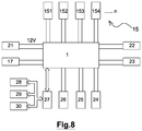
- FIG. 8 is a block diagram of the various interactions of the identification device according to the present invention with elements in its environment as in an automobile application;
- FIGS. 9A to 9D are respectively side, top, back and front views of a vehicle equipped with a radio reader for interacting with the identification device according to the present invention.
- FIG. 10 is a block diagram of a preferential embodiment of the identification device according to the invention.
- FIGS. 1A and 1B show an identification device 1 comprising a ring-shaped body 2 with an axis X incorporating a radio-frequency transponder 3 comprising a microcontroller (or chip 7 ) and an antenna 8 capable of emitting an electromagnetic field carrying identification data for communicating with a corresponding radio reader 15 (see FIG. 8 ).
- the transponder 3 is for example of the NFC or RFID type or can be any other autonomous remote communication transponder without any integrated power supply. Alternatively, several transponders 3 can be integrated into the annular body 2 so as to be identified by different types of radio readers 15 .
- the device 1 can be tightly sealed (or not), impermeable (or not), insensitive to granules, dust (or not) or any other substance/material that can generate an electromagnetic mask, or a deterioration of the assembly.
- the microcontroller 7 for example of the “MFOICU2” type of the company NXP Semiconductors comprises a radio-frequency interface 71 composed of a modulator/demodulator, a rectifier, a clock regenerator and a voltage regulator.
- the microcontroller 7 also includes cryptographic processors 72 for data for example with triple encryption and a cryptographic control unit 73 associated for controlling the operations of the cryptographic processors.
- a command interpreter 74 makes it possible to manage the commands for access the memory interface 75 in communication with a memory 76 .
- the memory 76 is a read-only memory. As an example and in a non-restrictive way, it can be of ROM, EPROM, EEPROM, or SSD type.
- the set of elements 72 , 73 , 74 , 75 is controlled by the digital control unit 77 .
- the memory 76 has 1536 bits organized in 48 pages with 32 bits each. 80 bits are reserved for the data of the manufacturer. 32 bits are used for the read-only locking mechanism. The 32 bits on pages 4 to 39 correspond to areas 761 storing personal data of a user. The areas of the memory 76 are considered as written in the logical state “1” and empty in the logic state “0”.
- the information contained in the memory 76 can be encrypted by using for example a symmetric encryption algorithm of AES (for “Advanced Encrypt ion Standard”) 256 bits type.
- the high-speed radio-frequency communication interface 71 enables the transmission of data at a speed of 106 kbit/s.
- Energy and data are transferred through the antenna 8 formed for example by a coil having some turns directly connected to the microcontroller 7 . No other external component is necessary.
- components of the diode, coil, and capacitor type could be used to process the signal before reception by the microcontroller 7 .
- the identification device 1 further comprises at least one photosensitive element 9 capable of generating a current when said element 9 is illuminated.
- the photosensitive element 9 is positioned on an inner face 19 of the ring 2 .
- the photosensitive element 9 is preferably a photovoltaic cell.
- the photovoltaic cell 9 can be replaced with a phototransistor, a photoresistor, or more generally any optoelectronic component capable of generating an electric current.
- the photovoltaic cell 9 can be integrated in different ways into the ring 2 .
- the cell 9 can be fixed on the surface, for example by gluing, or molded into the ring 2 .
- a window is provided in the ring next to the cell 9 .
- the cell 9 has a maximum spectral sensitivity at the wavelength of 580 nm and a wider sensitivity spectrum than that of the human eye.
- the photovoltaic cell 9 may be of different types, for example and in a non-limiting manner, the photovoltaic cell 9 used is made of monocrystalline, multi-crystalline (or polycrystalline) silicon, amorphous silicon, tandem, in CGIS (“Copper, Indium, Gallium, and Selenium”), cadmium telluride, and is of organic and/or multi junction type.
- CGIS Copper, Indium, Gallium, and Selenium
- cadmium telluride is of organic and/or multi junction type.
- All of these components are interconnected via wired connections 10 or a printed circuit board of the PCB (“Printed Circuit Board”) type.
- PCB printed Circuit Board
- the photovoltaic cell 9 is at least partially masked by the finger and does not produce a current sufficient to modify the memory areas 761 storing personal data of the user.
- the photovoltaic cell 9 When the ring 2 is removed from the user's finger, the photovoltaic cell 9 receives a light that can be either a natural light or an artificial light and produces a corresponding current, so as to generate a state logic causing deterioration of at least a part of the memory areas 761 storing the personal data of the user.
- the deterioration of the personal data of the user may consist for example of a total or partial erasure of these data in the corresponding memory areas or of a total or partial encryption of these data by an appropriate mathematical algorithm. So, the data can be encrypted by using for example a symmetric encryption algorithm of the AES (“Advanced Encryption Standard”) 256 bits type.
- the photovoltaic cell 9 can be indirectly responsible for the erasure of the data. For example, when the cell 9 is illuminated, the cell 9 controls the delivery of a current from another source of energy integrated in the ring 2 , for example one or more photovoltaic cells 9 on the outer periphery of ring 2 .
- the photosensitive element 9 does not provide enough current for erasing the data or to power the microcontroller 7 performing this operation.
- the photosensitive elements 9 provide a triggering function causing an energy storage system 31 to power the microcontroller 7 performing directly or indirectly the erasure, complete or not, of the data in the memory zones 761 .
- the photosensitive element 9 can for example cause the closure of an associated switch establishing an electrical connection between the storage system 31 and the microcontroller 7 so as to power this latter and erase the data.
- the energy stored in the system 31 comes from an energy recovery system 32 .
- the recovery system 32 may be suitable for directly or indirectly transform thermal or light energy into electric energy.
- the cells need to be reactive enough to quickly produce electric energy. According to ONE particular embodiment, these cells are tailor-made for the ring 2 .
- the cells do not exceed 1 mm thick and can be flexible.
- the cell can advantageously have a maximum spectral sensitivity at the wavelength of 580 nm and a wider sensitivity spectrum than that of the human eye.
- the energy recovery system 32 can also be formed by a mechanical system which, when in motion, can produce directly or indirectly an electric current. According to another embodiment of this mechanical device, a “small wheel” rubs against the finger when removing the ring and then produces electricity.
- the energy recovery system 32 can also be composed of an antenna. It recovers the electromagnetic energy from electromagnetic fields surrounding it so as to produce electric energy. These fields may depend on NFC frequencies as other frequencies such as WI-FI or radiotelephone frequencies.
- the energy recovery system 32 can also be able to recover the static electricity from the human body by means of electrodes in contact with the skin of the wearer. By holding a (very) negatively or (very) positively charged material, a difference in electrical potential will then be observed between the material and the body that carries the ring 2 .
- the electricity produced can be used directly or indirectly for erasing data. In this case of indirect use, it is stored in the energy storage system 31 .
- the energy recovery system 32 can also be a system based on a nano-generator, using a superposition of various flexible piezoelectric materials (e.g. polyvinylidene fluoride (PVDF), rigid plastic that can also be treated with zinc oxide).
- PVDF polyvinylidene fluoride
- This piezoelectric device has the ability to bend while generating electricity when subjected to vibrations, even weak vibrations.
- This recovery system 32 can be integrated into the inside or outside of the ring 2 so to generate electricity when significant friction occurs between the ring 2 and the finger or, when integrated on the external part, to generate electricity with the different mechanical contacts impacts that the ring 2 will undergo during a daily use.
- the energy storage system 31 can be formed by one or a plurality of capacitors 33 .
- the type of capacitor 33 can be based on aluminum foil, metalized paper, Mica, unpolarized electrochemical ceramic, polarized electrochemical ceramic and more specifically tantalums.
- the selected capacitor 33 can be of variable type.
- the identification device 1 can comprise a secure module 34 associated with an NFC controller that enables the use of the device 1 in the banking sector, in particular for secure transactions.
- a user interface 35 such as a diode, can also be inserted onto the ring 2 so as to inform the user that memory zones 761 are erased or not. For example, if the user removes the ring 2 and then put it again without copying her personal data when using it later, the electroluminescent diode 35 is illuminated in one color, for example red, for informing that the device 1 is not operational. Otherwise, the diode 35 illuminates in another color, for example in white or green, to inform that the device 1 is operational.
- the photovoltaic element 9 can be associated with an electronic switch 13 , shown in FIG. 5 , able to cause the erasure or encryption (deterioration) of the data from the zones 761 .
- the device 1 becomes unusable due to the deletion of the identification data.
- the user will have to make a copy of the data through a communicating device, such as a mobile phone or a tablet, in the memory the transponder 3 .
- a communicating device such as a mobile phone or a tablet
- the ring 2 will be worn by the user during the operation otherwise the copying would have no effect insofar the data would be instantly delete due to the illumination of the photovoltaic cell 9 .
- some user data is kept and associated with a customer account. In that case, only the original user is likely to be able to copy the missing data after deletion in the memory 76 of the transponder 3 . If the application of the communicating device observes that the user account does not match the device 1 then the copy of the data is blocked by the application.
- the photosensitive element 9 can be covered with a layer 91 of translucent protective varnish (see FIG. 1B ).
- the translucency of the varnish is a selection criterion for adjusting the sensitivity threshold of the cell 9 , so that the data are not erased with the slightest movement away from the cell 9 relative to the user's finger.
- the size of cell 9 will also be adapted according to the application for adjusting the sensitivity of the device 1 . Indeed, the larger the cell 9 , the more the cell 9 will capture light and thus the more the cell 9 will be sensitive. Thus, in the embodiment in FIGS. 3A and 3B , the size of the cell 9 is reduced relative to that of the cell in FIGS. 1A and 1B .
- the device 1 comprises a plurality of photovoltaic cells 9 , 9 ′, 9 ′′.
- a logic 14 is used, which integrates a system that is or can be similar to an “AND” type logical gate and whose output is in communication with the switch 13 .
- the cells 9 , 9 ′, 9 ′′ are preferably angularly spaced from each other in a regular manner around the ring 2 .
- the three cells 9 , 9 ′, and 9 ′′ are arranged so that the angles A 1 , A 2 , and A 3 between two consecutive cells are equal to 120 degrees.
- the ring 2 comprises an anti-rotation means 180 for locking the rotation of the ring 2 around a finger of the user.
- This anti-rotation means 180 has in this case an ovoid shape in the inner face 19 of the ring 2 and the side of the antenna 8 .
- the center of the oval shape coincides for example with the center of the ring 2 .
- the ratio R′ between the largest thickness E 1 of a ring portion having the ovoid shape and the basis thickness E 2 of the ring 2 is variable and comprised for example between 1 and 5, preferably between 1 and 3.
- the ratio R′ can thus be for example 1, 4 (see FIG. 7A ), 2.2 (see FIG. 7B ), or 2.6 (see FIG. 7C ).
- the ovoid shape can be replaced with a flat shape in the inner face 19 and in the outer face 200 (see FIG. 7D ), or only in the inner face 19 (see FIG. 7E ).
- the ratio R′ can also be variable and equal for example to 1 ( FIG. 7D ), or 3 ( FIG. 7E ).
- a flat or ovoid shape is provided along two diametrically opposite sides of the ring 2 . The specific shape of the ring 2 for correctly indexing the antenna 8 could be protected independently of the previously-described data erasure system.
- the energy storage system 31 has capacities 33 in the form of capacitors fixed to the PCB 10 .
- the photosensitive cell 9 which performs detection when the ring 2 is removed from the finger is covered by the varnish layer 91 .
- the elements 38 , 39 located on either side of the cell 9 are NFC controllers, as well as the secure module for working in the payment sector, allowing in particular banking transactions via the device 1 according to the invention.
- the transponder 3 can for example communicate with N directional radio readers 15 (N being an integer superior or equal to 1) in a vehicle 20 . This communication enables a carrier of the identification device 1 to access rights and/or services.
- each radio frequency reader 15 comprises a receiving antenna for the transponder 3 .
- This antenna is preferably in the form of a coil of rectangular section associated with a capacitor to form a resonant antenna.
- Such an antenna concentrates its energy in certain directions and is designed to operate optimally at a certain resonant frequency and for a precise adaptation resistance. To make this antenna less sensitive to the surrounding metallic elements, its resonance frequency and its adaptation resistance have been adapted.
- a coil of about 3 mH having a matching resistance of about 250 to 500 ohms provides the radio reader 15 with an optimal quality signal.
- the resonance frequency is not necessarily set at the frequency of the electromagnetic field emitted by the transponder 3 . Indeed, a better reception of the electromagnetic field is obtained when the resonance frequency of the antenna of the radio reader 15 is superior to 5 to 20% of the frequency of the electromagnetic field.
- the power supply for the radio reader 15 is provided by a battery 21 in the vehicle 20 and generally delivers a voltage of 12 volts.
- This type of radio reader 15 is placed so as to optimize the reading of the electromagnetic field emitted by the transponder 3 .
- the radio readers 15 were in this case integrated in a door handle 151 , in a trunk handle 152 , in a gearshift knob 153 , and near a safety belt buckle 154 .
- the radio readers 15 can be integrated onto the fuel tank or into the acceleration handle.
- the electromagnetic field is slightly attenuated by a glove-type textile interposed between the transponder 3 and the radio reader 15 .
- the radio readers 15 are in the form of a solenoid comprising about 400 turns having an inductance of about 3 mH.
- the form, their adaptation resistance, their resonance frequency, and the number N of radio readers 15 are not limited.
- the device 1 when the wearer grasps the handle of a vehicle door 20 to open it with his hand carrying the identification device 1 in an activated state, the device 1 undergoes an electromagnetic induction from the radio reader 151 integrated in the handle.
- the induced current of about 10 A and 5V, is sufficient to power the transponder 3 which sends back to the antenna of the radio reader 151 a high security identification code preprogrammed during the manufacture thereof or a copy made by the communicating device.
- This identification code is then filtered, demodulated and analyzed by a microcontroller in an electronic circuit near the radio reader 153 .
- the identification device 1 is then recognized, the vehicle 20 is instantly unlocked and an adaptation of the driving position is quickly carried out within a time of about 4 to 6 seconds.
- a switch 17 controls the powering up of the electronic circuit in the vehicle under the control of the housing 18 , thereby enabling a radio reader 153 to emit a strong magnetic field.
- an ignition switch 17 controlling the preheating, starting and stopping of the engine in the vehicle 20 is associated with an starting radio reader 153 in the gearshift knob.
- the switch 17 may be placed in the cockpit, at hand of the driver such as on the side of gearshift knob, close to the hand brake, or on the dashboard.
- Such a switch 17 can be parallel to the conventional starting system by connecting preheating and starting control wires to relevant actuators of the engine or by connecting them to a key switch 23 .
- the vehicle 20 starts.
- the vehicle 20 remains in operating condition until a further press on the switch 17 .
- the starting radio reader 153 detects the identification device 1 and when the user presses the switch 17 , the associated reader 153 switches to an unpowered state. In this state, the reader 153 no longer needs identification to keep the engine running.
- the radio reader 153 will be stopped simultaneously. The radio reader 153 will then request the high security identification code from the identification device 1 .
- the N readers generally move from one powered state to another depending on the state of locking or unlocking of the vehicle 20 , with the exception of the starting radio reader 153 and the reader 152 in the trunk handle. Indeed, whatever the locking or unlocking of the vehicle 20 , the reader 152 can actuate cylinders for opening the trunk automatically.
- each radio reader 15 can also be associated with a switch 17 .
- the identification device 1 can operate a central locking and unlocking control 22 on a key switch 23 , on various accessories 24 , on a driver's seat 25 , on rear-view mirrors 26 , and on an interface 27 controlling an on-board computer 28 , a GPS 29 , and a vehicle configuration.
- These various commands operate via actuators controlling for example the position and orientation of the mirrors 26 , the position, the height, the inclination of the driver's seat 25 and its headrest, the position of the steering wheel.
- the device 1 can also control the display of a computer screen 28 , the radio station heard, the voice of the GPS 29 , the height of the suspensions and their hardness, the power steering hardness, the driver assistance electronics, the driving profile, the vehicle power, and a possible restraining of the engine for young drivers.
- the identification device 1 is synchronized with the absolute time clock sent by the GPS.
- the identification device 1 can also be connected to the Internet via a cellular data connection, by Wi-Fi or Bluetooth, thereby enabling interaction with the database.
- the identification devices 1 containing a certain number of its characteristics, for example and without limitation: the identification profiles, the configuration of the driving position, the driving history, the driving scheduling, the consumption of fuel, the mileage carried out or to carried out, the route programmed in GPS the 29, and the route really taken.
- identification devices 1 can be synchronized to the same vehicle 20 .
- the registration of the identification devices 1 , the driving position, and the engine configuration is carried out by actuating a specific command of the electronic circuit 18 interacting with the microcontroller.
- each wearer using the vehicle 20 can be identified.
- the entire driving position, as well as the characteristics of the engine can be adapted, hours of use, as well as history can be recorded.
- the specific control of the electronic circuit 18 can be in the form of a switch, a code keypad, or an Internet-type remote access.
- an identification device 1 thus enables a simplified and secure identification.
- this device 1 which does not require a battery, does not risk oxidization. More advantageously, the device 1 enables the wearer to operate her/his identification device 1 , when s/he wants to, there avoiding any inadvertent operation without control of the wearer.
- the radio frequency transponder 3 can comprise, in a variant, several microcontrollers 7 and several antennas 8 . Furthermore, the exemplary embodiment has been given with reference to a user's personal data, but the invention can of course be implemented with any type of data stored in the memory 76 in the microcontroller.
Landscapes
- Engineering & Computer Science (AREA)
- Physics & Mathematics (AREA)
- General Physics & Mathematics (AREA)
- Computer Hardware Design (AREA)
- Theoretical Computer Science (AREA)
- Computer Security & Cryptography (AREA)
- Microelectronics & Electronic Packaging (AREA)
- General Engineering & Computer Science (AREA)
- Computer Networks & Wireless Communication (AREA)
- Software Systems (AREA)
- Signal Processing (AREA)
- Lock And Its Accessories (AREA)
Abstract
Description
Claims (12)
Applications Claiming Priority (3)
| Application Number | Priority Date | Filing Date | Title |
|---|---|---|---|
| FR1650866A FR3047369B1 (en) | 2016-02-03 | 2016-02-03 | RING-TYPE RADIO FREQUENCY IDENTIFICATION DEVICE HAVING A SYSTEM FOR DETERIORATING PERSONAL DATA IN THE EVENT OF LOSS OR THEFT |
| FR1650866 | 2016-02-03 | ||
| PCT/EP2017/052276 WO2017134174A1 (en) | 2016-02-03 | 2017-02-02 | Radiofrequency identification device in the form of a ring provided with a system for deteriorating personal data in the event of loss or theft |
Publications (2)
| Publication Number | Publication Date |
|---|---|
| US20190043284A1 US20190043284A1 (en) | 2019-02-07 |
| US10497195B2 true US10497195B2 (en) | 2019-12-03 |
Family
ID=56511636
Family Applications (1)
| Application Number | Title | Priority Date | Filing Date |
|---|---|---|---|
| US16/074,772 Expired - Fee Related US10497195B2 (en) | 2016-02-03 | 2017-02-02 | Radiofrequency identification device in the form of a ring provided with a system for deteriorating personal data in the event of loss or theft |
Country Status (4)
| Country | Link |
|---|---|
| US (1) | US10497195B2 (en) |
| EP (1) | EP3411855B1 (en) |
| FR (1) | FR3047369B1 (en) |
| WO (1) | WO2017134174A1 (en) |
Cited By (1)
| Publication number | Priority date | Publication date | Assignee | Title |
|---|---|---|---|---|
| USD1063935S1 (en) * | 2022-11-30 | 2025-02-25 | Oura Health Oy | Biometric ring wearable device |
Families Citing this family (2)
| Publication number | Priority date | Publication date | Assignee | Title |
|---|---|---|---|---|
| FR3088743B1 (en) * | 2018-11-21 | 2021-11-12 | Icare Tech | communicating ring fitted with a mechanical failure ZONE and / or a fuse TO INHIBIT AT LEAST ONE FUNCTIONALITY IN THE EVENT OF AN ASSAULT |
| CN111768523B (en) * | 2020-06-10 | 2022-07-26 | 福建新大陆通信科技股份有限公司 | CTID-based NFC intelligent door lock unlocking method, system, equipment and medium |
Citations (13)
| Publication number | Priority date | Publication date | Assignee | Title |
|---|---|---|---|---|
| US3919596A (en) * | 1973-01-31 | 1975-11-11 | Robert Elliott Bellis | Touch sensitive power control system |
| US20080171915A1 (en) * | 2005-03-10 | 2008-07-17 | Momoe Kawajiri | Biological Signal Measurement Device, Biological Signal Measurement Method, And Computer Program |
| US20110271053A1 (en) | 2008-10-07 | 2011-11-03 | Asmag-Holding Gmbh | Mobile data memory with automatic delete function |
| US20120036758A1 (en) * | 2010-08-16 | 2012-02-16 | Steffens David A | Fish landing net |
| US20120152310A1 (en) * | 2010-12-17 | 2012-06-21 | Greenvolts, Inc. | Structurally breaking up a solar array of a two-axis tracker assembly in a concentrated photovoltaic system |
| US20120229487A1 (en) * | 2011-03-11 | 2012-09-13 | Nokia Corporation | Method and Apparatus for Reflection Compensation |
| US20150028996A1 (en) * | 2013-07-25 | 2015-01-29 | Bionym Inc. | Preauthorized wearable biometric device, system and method for use thereof |
| US20150178532A1 (en) * | 2012-06-20 | 2015-06-25 | David Allen Brulé | Wearable rfid storage devices |
| US20150220109A1 (en) | 2013-11-29 | 2015-08-06 | Mechio Inc. | Wearable computing device |
| US20160156603A1 (en) * | 2014-11-28 | 2016-06-02 | Craig Janik | Low Power Secure User Identity Authentication Ring |
| US20160334110A1 (en) * | 2014-01-10 | 2016-11-17 | BSH Hausgeräte GmbH | Operating device for domestic appliance |
| FR3036213A1 (en) | 2015-05-13 | 2016-11-18 | Jeremy Neyrou | RING IDENTIFICATION DEVICE PROVIDED WITH A RADIOFREQUETIAL TRANSPONDER |
| US20170020191A1 (en) * | 2015-07-24 | 2017-01-26 | R. J. Reynolds Tobacco Company | Radio-frequency identification (rfid) authentication system for aerosol delivery devices |
Family Cites Families (1)
| Publication number | Priority date | Publication date | Assignee | Title |
|---|---|---|---|---|
| CH463874A (en) | 1967-02-14 | 1968-10-15 | Hegglin Emil | Oil cooling device on an internal combustion engine |
-
2016
- 2016-02-03 FR FR1650866A patent/FR3047369B1/en not_active Expired - Fee Related
-
2017
- 2017-02-02 WO PCT/EP2017/052276 patent/WO2017134174A1/en not_active Ceased
- 2017-02-02 US US16/074,772 patent/US10497195B2/en not_active Expired - Fee Related
- 2017-02-02 EP EP17702388.4A patent/EP3411855B1/en not_active Not-in-force
Patent Citations (14)
| Publication number | Priority date | Publication date | Assignee | Title |
|---|---|---|---|---|
| US3919596A (en) * | 1973-01-31 | 1975-11-11 | Robert Elliott Bellis | Touch sensitive power control system |
| US20080171915A1 (en) * | 2005-03-10 | 2008-07-17 | Momoe Kawajiri | Biological Signal Measurement Device, Biological Signal Measurement Method, And Computer Program |
| US20110271053A1 (en) | 2008-10-07 | 2011-11-03 | Asmag-Holding Gmbh | Mobile data memory with automatic delete function |
| US20120036758A1 (en) * | 2010-08-16 | 2012-02-16 | Steffens David A | Fish landing net |
| US20120152310A1 (en) * | 2010-12-17 | 2012-06-21 | Greenvolts, Inc. | Structurally breaking up a solar array of a two-axis tracker assembly in a concentrated photovoltaic system |
| US20120229487A1 (en) * | 2011-03-11 | 2012-09-13 | Nokia Corporation | Method and Apparatus for Reflection Compensation |
| US20150178532A1 (en) * | 2012-06-20 | 2015-06-25 | David Allen Brulé | Wearable rfid storage devices |
| US20150028996A1 (en) * | 2013-07-25 | 2015-01-29 | Bionym Inc. | Preauthorized wearable biometric device, system and method for use thereof |
| US20150220109A1 (en) | 2013-11-29 | 2015-08-06 | Mechio Inc. | Wearable computing device |
| US20160334110A1 (en) * | 2014-01-10 | 2016-11-17 | BSH Hausgeräte GmbH | Operating device for domestic appliance |
| US20160156603A1 (en) * | 2014-11-28 | 2016-06-02 | Craig Janik | Low Power Secure User Identity Authentication Ring |
| FR3036213A1 (en) | 2015-05-13 | 2016-11-18 | Jeremy Neyrou | RING IDENTIFICATION DEVICE PROVIDED WITH A RADIOFREQUETIAL TRANSPONDER |
| US20180089478A1 (en) | 2015-05-13 | 2018-03-29 | I Care Technologies | Identification device in the form of a ring provided with a radiofrequency transponder |
| US20170020191A1 (en) * | 2015-07-24 | 2017-01-26 | R. J. Reynolds Tobacco Company | Radio-frequency identification (rfid) authentication system for aerosol delivery devices |
Cited By (1)
| Publication number | Priority date | Publication date | Assignee | Title |
|---|---|---|---|---|
| USD1063935S1 (en) * | 2022-11-30 | 2025-02-25 | Oura Health Oy | Biometric ring wearable device |
Also Published As
| Publication number | Publication date |
|---|---|
| FR3047369A1 (en) | 2017-08-04 |
| FR3047369B1 (en) | 2019-06-21 |
| WO2017134174A1 (en) | 2017-08-10 |
| EP3411855A1 (en) | 2018-12-12 |
| EP3411855B1 (en) | 2021-12-08 |
| US20190043284A1 (en) | 2019-02-07 |
Similar Documents
| Publication | Publication Date | Title |
|---|---|---|
| US10943000B2 (en) | System and method for supplying security information | |
| JP5908588B2 (en) | Security system and device | |
| ES2816201T3 (en) | Biometric registration | |
| US6992565B1 (en) | Electronic communications system | |
| US9134956B2 (en) | In-vehicle system, vehicle control method, and vehicle control system | |
| ES2734367T3 (en) | Closing unit, closing device and procedure for unlocking and / or locking a lock | |
| US10497195B2 (en) | Radiofrequency identification device in the form of a ring provided with a system for deteriorating personal data in the event of loss or theft | |
| US20180089478A1 (en) | Identification device in the form of a ring provided with a radiofrequency transponder | |
| EP0767286A2 (en) | Remote keyless entry and immobilization system for automotive use | |
| US10244396B2 (en) | Ring-shaped identification device equipped with a radiofrequency transponder controlled by a light-sensitive element | |
| CN104813368A (en) | Radio key for a vehicle | |
| US20190217817A1 (en) | Control device and method for unlocking a motor vehicle with integrated nfc-control device | |
| US20220156544A1 (en) | Key Fob | |
| EP3680865A1 (en) | Control system for interconnecting electric bike and electronic lock | |
| US10341863B2 (en) | Method and system for authenticating a user and a motor vehicle | |
| CN118736706A (en) | Hidden security key using Near Field Communication | |
| US11713022B1 (en) | NFC-based enclosure access using passive energy harvesting | |
| KR102514994B1 (en) | Method for operating lock device | |
| WO2018002367A1 (en) | Biometric device with low power usage | |
| KR102664698B1 (en) | Fingerprint authentification controller for vehicle and method using thereof | |
| JP2005226284A (en) | Operation management system and portable operation management device used therefor | |
| JP2597044B2 (en) | IC card | |
| JP4486016B2 (en) | Communication terminal | |
| WO2024029285A1 (en) | User authentication method, user authentication digital key system, and mobile device program | |
| WO2011043245A1 (en) | Data communication system |
Legal Events
| Date | Code | Title | Description |
|---|---|---|---|
| FEPP | Fee payment procedure |
Free format text: ENTITY STATUS SET TO UNDISCOUNTED (ORIGINAL EVENT CODE: BIG.); ENTITY STATUS OF PATENT OWNER: SMALL ENTITY |
|
| AS | Assignment |
Owner name: ICARE TECHNOLOGIES, FRANCE Free format text: ASSIGNMENT OF ASSIGNORS INTEREST;ASSIGNORS:NEYROU, JEREMY;RAIOLA, FABIEN;REEL/FRAME:046545/0788 Effective date: 20180725 |
|
| FEPP | Fee payment procedure |
Free format text: ENTITY STATUS SET TO SMALL (ORIGINAL EVENT CODE: SMAL); ENTITY STATUS OF PATENT OWNER: SMALL ENTITY |
|
| STPP | Information on status: patent application and granting procedure in general |
Free format text: NON FINAL ACTION MAILED |
|
| STPP | Information on status: patent application and granting procedure in general |
Free format text: RESPONSE TO NON-FINAL OFFICE ACTION ENTERED AND FORWARDED TO EXAMINER |
|
| STPP | Information on status: patent application and granting procedure in general |
Free format text: NOTICE OF ALLOWANCE MAILED -- APPLICATION RECEIVED IN OFFICE OF PUBLICATIONS |
|
| STPP | Information on status: patent application and granting procedure in general |
Free format text: PUBLICATIONS -- ISSUE FEE PAYMENT VERIFIED |
|
| STCF | Information on status: patent grant |
Free format text: PATENTED CASE |
|
| FEPP | Fee payment procedure |
Free format text: MAINTENANCE FEE REMINDER MAILED (ORIGINAL EVENT CODE: REM.); ENTITY STATUS OF PATENT OWNER: SMALL ENTITY |
|
| LAPS | Lapse for failure to pay maintenance fees |
Free format text: PATENT EXPIRED FOR FAILURE TO PAY MAINTENANCE FEES (ORIGINAL EVENT CODE: EXP.); ENTITY STATUS OF PATENT OWNER: SMALL ENTITY |
|
| STCH | Information on status: patent discontinuation |
Free format text: PATENT EXPIRED DUE TO NONPAYMENT OF MAINTENANCE FEES UNDER 37 CFR 1.362 |
|
| FP | Lapsed due to failure to pay maintenance fee |
Effective date: 20231203 |