US10487875B2 - Magnetic bearing device - Google Patents
Magnetic bearing device Download PDFInfo
- Publication number
- US10487875B2 US10487875B2 US15/686,790 US201715686790A US10487875B2 US 10487875 B2 US10487875 B2 US 10487875B2 US 201715686790 A US201715686790 A US 201715686790A US 10487875 B2 US10487875 B2 US 10487875B2
- Authority
- US
- United States
- Prior art keywords
- tpwm
- signal
- cycle
- magnetic bearing
- current
- Prior art date
- Legal status (The legal status is an assumption and is not a legal conclusion. Google has not performed a legal analysis and makes no representation as to the accuracy of the status listed.)
- Active, expires
Links
Images


Classifications
-
- F—MECHANICAL ENGINEERING; LIGHTING; HEATING; WEAPONS; BLASTING
- F16—ENGINEERING ELEMENTS AND UNITS; GENERAL MEASURES FOR PRODUCING AND MAINTAINING EFFECTIVE FUNCTIONING OF MACHINES OR INSTALLATIONS; THERMAL INSULATION IN GENERAL
- F16C—SHAFTS; FLEXIBLE SHAFTS; ELEMENTS OR CRANKSHAFT MECHANISMS; ROTARY BODIES OTHER THAN GEARING ELEMENTS; BEARINGS
- F16C32/00—Bearings not otherwise provided for
- F16C32/04—Bearings not otherwise provided for using magnetic or electric supporting means
- F16C32/0406—Magnetic bearings
- F16C32/044—Active magnetic bearings
- F16C32/0444—Details of devices to control the actuation of the electromagnets
- F16C32/0451—Details of controllers, i.e. the units determining the power to be supplied, e.g. comparing elements, feedback arrangements with P.I.D. control
- F16C32/0455—Details of controllers, i.e. the units determining the power to be supplied, e.g. comparing elements, feedback arrangements with P.I.D. control including digital signal processing [DSP] and analog/digital conversion [A/D, D/A]
-
- F—MECHANICAL ENGINEERING; LIGHTING; HEATING; WEAPONS; BLASTING
- F16—ENGINEERING ELEMENTS AND UNITS; GENERAL MEASURES FOR PRODUCING AND MAINTAINING EFFECTIVE FUNCTIONING OF MACHINES OR INSTALLATIONS; THERMAL INSULATION IN GENERAL
- F16C—SHAFTS; FLEXIBLE SHAFTS; ELEMENTS OR CRANKSHAFT MECHANISMS; ROTARY BODIES OTHER THAN GEARING ELEMENTS; BEARINGS
- F16C32/00—Bearings not otherwise provided for
- F16C32/04—Bearings not otherwise provided for using magnetic or electric supporting means
- F16C32/0406—Magnetic bearings
- F16C32/044—Active magnetic bearings
- F16C32/0444—Details of devices to control the actuation of the electromagnets
- F16C32/0446—Determination of the actual position of the moving member, e.g. details of sensors
- F16C32/0448—Determination of the actual position of the moving member, e.g. details of sensors by using the electromagnet itself as sensor, e.g. sensorless magnetic bearings
-
- F—MECHANICAL ENGINEERING; LIGHTING; HEATING; WEAPONS; BLASTING
- F16—ENGINEERING ELEMENTS AND UNITS; GENERAL MEASURES FOR PRODUCING AND MAINTAINING EFFECTIVE FUNCTIONING OF MACHINES OR INSTALLATIONS; THERMAL INSULATION IN GENERAL
- F16C—SHAFTS; FLEXIBLE SHAFTS; ELEMENTS OR CRANKSHAFT MECHANISMS; ROTARY BODIES OTHER THAN GEARING ELEMENTS; BEARINGS
- F16C32/00—Bearings not otherwise provided for
- F16C32/04—Bearings not otherwise provided for using magnetic or electric supporting means
- F16C32/0406—Magnetic bearings
- F16C32/044—Active magnetic bearings
- F16C32/0474—Active magnetic bearings for rotary movement
- F16C32/0489—Active magnetic bearings for rotary movement with active support of five degrees of freedom, e.g. two radial magnetic bearings combined with an axial bearing
- F16C32/0491—Active magnetic bearings for rotary movement with active support of five degrees of freedom, e.g. two radial magnetic bearings combined with an axial bearing with electromagnets acting in axial and radial direction, e.g. with conical magnets
-
- H—ELECTRICITY
- H02—GENERATION; CONVERSION OR DISTRIBUTION OF ELECTRIC POWER
- H02K—DYNAMO-ELECTRIC MACHINES
- H02K7/00—Arrangements for handling mechanical energy structurally associated with dynamo-electric machines, e.g. structural association with mechanical driving motors or auxiliary dynamo-electric machines
- H02K7/08—Structural association with bearings
- H02K7/09—Structural association with bearings with magnetic bearings
-
- F—MECHANICAL ENGINEERING; LIGHTING; HEATING; WEAPONS; BLASTING
- F16—ENGINEERING ELEMENTS AND UNITS; GENERAL MEASURES FOR PRODUCING AND MAINTAINING EFFECTIVE FUNCTIONING OF MACHINES OR INSTALLATIONS; THERMAL INSULATION IN GENERAL
- F16C—SHAFTS; FLEXIBLE SHAFTS; ELEMENTS OR CRANKSHAFT MECHANISMS; ROTARY BODIES OTHER THAN GEARING ELEMENTS; BEARINGS
- F16C2360/00—Engines or pumps
- F16C2360/44—Centrifugal pumps
- F16C2360/45—Turbo-molecular pumps
-
- F—MECHANICAL ENGINEERING; LIGHTING; HEATING; WEAPONS; BLASTING
- F16—ENGINEERING ELEMENTS AND UNITS; GENERAL MEASURES FOR PRODUCING AND MAINTAINING EFFECTIVE FUNCTIONING OF MACHINES OR INSTALLATIONS; THERMAL INSULATION IN GENERAL
- F16C—SHAFTS; FLEXIBLE SHAFTS; ELEMENTS OR CRANKSHAFT MECHANISMS; ROTARY BODIES OTHER THAN GEARING ELEMENTS; BEARINGS
- F16C32/00—Bearings not otherwise provided for
- F16C32/04—Bearings not otherwise provided for using magnetic or electric supporting means
- F16C32/0406—Magnetic bearings
- F16C32/044—Active magnetic bearings
- F16C32/0442—Active magnetic bearings with devices affected by abnormal, undesired or non-standard conditions such as shock-load, power outage, start-up or touchdown
-
- F—MECHANICAL ENGINEERING; LIGHTING; HEATING; WEAPONS; BLASTING
- F16—ENGINEERING ELEMENTS AND UNITS; GENERAL MEASURES FOR PRODUCING AND MAINTAINING EFFECTIVE FUNCTIONING OF MACHINES OR INSTALLATIONS; THERMAL INSULATION IN GENERAL
- F16C—SHAFTS; FLEXIBLE SHAFTS; ELEMENTS OR CRANKSHAFT MECHANISMS; ROTARY BODIES OTHER THAN GEARING ELEMENTS; BEARINGS
- F16C32/00—Bearings not otherwise provided for
- F16C32/04—Bearings not otherwise provided for using magnetic or electric supporting means
- F16C32/0406—Magnetic bearings
- F16C32/044—Active magnetic bearings
- F16C32/0474—Active magnetic bearings for rotary movement
- F16C32/0489—Active magnetic bearings for rotary movement with active support of five degrees of freedom, e.g. two radial magnetic bearings combined with an axial bearing
Definitions
- the present invention relates to a magnetic bearing device.
- magnetic suction power of an electromagnet is, for levitating a rotor to a predetermined target position, controlled in real time based on a deviation (a displacement) between a rotor levitation position and the target position.
- electromagnet current i.e., electromagnet current
- a sensorless method also called a “self-sensing method”
- an electromagnet has both of a typical actuator function (generation of magnetic levitation suction power) and a sensing function.
- an inductance method is employed for the sensing function.
- a high-frequency carrier (a sensor carrier) is applied to a sensor coil or an electromagnet coil, and the amplitude of the sensor carrier is modulated according to an inductance change due to a levitation gap.
- the resultant is demodulated, and as a result, a levitation gap signal (a displacement signal) is obtained.
- the actuator function for generating the magnetic suction power it is configured such that a switching voltage is applied from a PWM amplifier to the electromagnet coil to supply an excitation current.
- the electromagnet has not only the actuator function but also the sensing function, and levitation position information (displacement information) of the rotor body is obtained by detection of the electromagnet current.
- the PWM amplifier is driven with voltage.
- the control of feeding back the value of current flowing through the electromagnet after detection thereof is required.
- spike-shaped noise due to, e.g., surge voltage is caused in the electromagnet current at switching timing, leading to a problem that the noise is superimposed on a detected current signal.
- spike-shaped noise is also superimposed on a detected current signal or displacement signal for other axes via ground line current.
- the frequency fpwm of the PWM carrier signal, the frequency fc of a sensor carrier signal, and the frequency fs in AD sampling are set to an integral multiple relationship. With such settings, current detection signals and sum signals (detection signals corresponding to a displacement) of electromagnets for multiple axes are simultaneously and collectively AD-sampled.
- a magnetic bearing device comprises: a pair of electromagnets provided for each of multiple control axes and arranged to face each other with respect to a rotor shaft;
- a plurality of excitation amplifiers configured to supply an electromagnet current to each electromagnet; a plurality of current sensors each configured to detect the electromagnet current to output a current detection signal; and a controller configured to AD-sample (i) the current detection signal based on the electromagnet current on which a carrier signal for detecting a change in a levitation position of the rotor shaft is superimposed, and a sum signal of the current detection signals of the pair of electromagnets, or (ii) the current detection signal, and a modulated signal produced by modulating a carrier signal based on the levitation position, in a predetermined AD sampling period to obtain displacement information on the levitation position change, thereby performing PWM control of each excitation amplifier based on the displacement information.
- the AD sampling period includes a first AD sampling period between a point after a lapse of the time Td after a start of the cycle Tpwm and a point after a lapse of a time (Tpwm ⁇ Tonu) from the start of the cycle Tpwm, and a second AD sampling period between a point after a lapse of a time (Tpwm ⁇ Tonl+Td) from the start of the cycle Tpwm and an end point of the cycle Tpwm.
- the magnetic bearing device further comprises a carrier generator configured to generate the carrier signal for detecting the change in the levitation position of the rotor shaft; and a displacement sensor configured to modulate the carrier signal based on the levitation position change to output the modulated signal.
- the controller AD-samples each current detection signal and the modulated signal in the predetermined AD sampling period to obtain displacement information on the levitation position change, thereby performing PWM control of each excitation amplifier based on the displacement information.
- the plurality of excitation amplifiers supply, to each electromagnet, the electromagnet current on which the carrier signal for detecting the change in the levitation position of the rotor shaft is superimposed.
- the magnetic bearing device further comprising a sum signal obtainer configured to add up the current detection signals of the pair of electromagnets to obtain the sum signal.
- the controller AD-samples each current detection signal and the sum signal in the predetermined AD sampling period to obtain displacement information on the levitation position change, thereby performing PWM control of each excitation amplifier based on the displacement information.
- the first AD sampling period is set to a period between the point after the lapse of the time Td from the start of the cycle Tpwm and a point after a lapse of a time (Td+Tmin) from the start of the cycle Tpwm
- the second AD sampling period is set to a period between a point after a lapse of a time (Tpwm ⁇ Tmin) from the start of the cycle Tpwm and the end point of the cycle Tpwm.
- the first AD sampling period is set to a period between a point after a lapse of 10% of the cycle Tpwm from the start of the cycle Tpwm and a point after a lapse of 40% of the cycle Tpwm from the start of the cycle Tpwm
- the second AD sampling period is set to a period between a point after a lapse of 70% of the cycle Tpwm from the start of the cycle Tpwm and a point after a lapse of 90% of the cycle Tpwm from the start of the cycle Tpwm.
- a frequency of the PWM carrier signal is fpwm
- a frequency of the carrier signal is fc
- a frequency in the AD sampling is fs
- the magnetic bearing device further comprises: an obtainer configured to obtain such a frequency that an on-duty duration in the PWM carrier signal is equal to or shorter than (Td+Tmin) or equal to or longer than (Tpwm ⁇ Td ⁇ Tmin); and a warner configured to emit a warning when the frequency exceeds a predetermined frequency threshold.
- the magnetic bearing device further comprises: a holder configured to hold multiple different frequency thresholds. Any of the multiple frequency thresholds is alternatively set.
- the AD converter employing the method for collectively taking the multiple signals is not necessary for AD sampling, and there is no probability that the variable duty range in PWM control is limited more than necessary.
- FIG. 1 is a sectional view of an outline configuration of a magnetic bearing turbo-molecular pump
- FIG. 2 is a block diagram of an outline configuration of a control unit
- FIG. 3 is a schematic diagram of a magnetic bearing electromagnet for a single control axis
- FIG. 4 is a diagram of an excitation amplifier configuration
- FIG. 5 is a graph of an example of voltage applied to an electromagnet coil and current flowing through the electromagnet coil
- FIG. 6 is a graph of an enlarged portion indicated by a reference character “B” of FIG. 5 ;
- FIGS. 7A and 7B are graphs for describing a relationship between PWM-modulated electromagnet current (a line L 10 ) and spike noise C;
- FIG. 8 is a graph for describing the ranges of Expressions (A) to (D);
- FIG. 9 is a graph of an example of sampling timing in the case of setting the ranges as in Expressions (C) and (D);
- FIG. 10 is a chart of sampling timing of each current detection signal
- FIG. 11 is a chart of an example of sampling timing of each sum signal
- FIG. 12 is a functional block diagram in magnetic bearing control in a controller
- FIG. 13 is a block diagram of a control system in a second embodiment
- FIG. 14 is a functional block diagram in magnetic bearing control in the case of providing displacement sensors
- FIG. 15 is a chart of sampling timing of each displacement sensor
- FIG. 16 is a chart of sampling timing
- FIG. 17 is a chart for describing a third embodiment of the present invention.
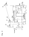
- FIG. 1 is a sectional view of an outline configuration of a turbo-molecular pump to which a magnetic bearing device of a first embodiment of the present invention is applied.
- the turbo-molecular pump includes a pump main body 1 illustrated in FIG. 1 , and a control unit (not shown) configured to drive the pump main body 1 .
- the pump main body 1 includes a turbo pump stage having rotor blades 4 a and stationary blades 62 , and a drag pump stage (a screw groove pump) having a cylindrical portion 4 b and a screw stator 64 .
- a screw groove is formed at the screw stator 64 , but may be formed at the cylindrical portion 4 b.
- the rotor blades 4 a and the cylindrical portion 4 b are formed at a pump rotor 4 .
- the pump rotor 4 is fastened to a shaft 5 .
- the pump rotor 4 and the shaft 5 form a rotor unit R.
- the stationary blades 62 and the rotor blades 4 a are alternately arranged in an axial direction. Each stationary blade 62 is placed on a base 60 with a spacer ring 63 being interposed therebetween.
- the shaft 5 is non-contact supported by magnetic bearings 67 , 68 , 69 .
- the magnetic bearings 67 , 68 , 69 form a five-axis magnetic bearing. Electromagnets forming the magnetic bearing 69 are arranged to sandwich a rotor disc 55 in the axial direction, the rotor disc 55 being configured to rotate together with the shaft 5 .
- the magnetic bearings 67 , 68 , 69 are self-sensing magnetic bearings configured to estimate a change in a levitation position based on electromagnet current on which a sensor carrier component is superimposed.
- a motor 42 is a synchronous motor, and in the present embodiment, a DC brushless motor is used.
- the motor 42 has a motor stator 42 a disposed at the base 60 , and a motor rotor 42 b provided at the shaft 5 .
- a permanent magnet is provided at the motor rotor 42 b .
- the shaft 5 is supported by emergency mechanical bearings 66 a , 66 b.
- An exhaust port 65 is provided at an exhaust port 60 a of the base 60 , and a back pump is connected to the exhaust port 65 .
- the rotor unit R is magnetically levitated while being rotatably driven at high speed by the motor 42 , and in this manner, gas molecules are exhausted from a suction port 61 a to the exhaust port 65 .
- FIG. 2 is a block diagram of an outline configuration of a control system (the control unit).
- AC input from the outside is converted from AC into DC by a DC power supply 40 provided at the control unit.
- the DC power supply 40 forms a power supply for an inverter 41 , a power supply for each excitation amplifier 43 , and a power supply for the controller 44 .
- the inverter 41 configured to supply current to the motor 42 includes a plurality of switching elements.
- the motor 42 is driven in such a manner that the controller 44 controls ON/OFF of these switching elements.
- Ten magnetic bearing electromagnets 45 illustrated in FIG. 2 indicate magnetic bearing electromagnets provided for the magnetic bearings 67 , 68 , 69 .
- the magnetic bearings used for the turbo-molecular pump illustrated in FIG. 1 form the five-axis control magnetic bearing.
- the radial magnetic bearings 67 , 68 are each a biaxial magnetic bearing, and each include two pairs of magnetic bearing electromagnets 45 (four magnetic bearing electromagnets 45 ).
- the axial magnetic bearing 69 is a uniaxial magnetic bearing, and includes a pair of magnetic bearing electromagnets 45 (two magnetic bearing electromagnets 45 ).
- the excitation amplifier 43 configured to supply current to the magnetic bearing electromagnets 45 is provided for each of ten magnetic bearing electromagnets 45 .
- the controller 44 configured to control driving of the motor 42 and driving of the magnetic bearings includes, for example, a digital arithmetic unit such as a field programmable gate array (FPGA), and a peripheral circuit thereof.
- a PWM control signal 441 for controlling ON/OFF of the plurality of switching elements provided at the inverter 41 is input from the controller 44 to the inverter 41 .
- a signal 442 on the phase voltage and phase current of the motor 42 is input from the inverter 41 to the controller 44 .
- a PWM gate drive signal 443 for controlling ON/OFF of a switching element included in each excitation amplifier 43 is input from the controller 44 to each excitation amplifier 43 .
- a current detection signal 444 on a current value of each magnetic bearing electromagnet 45 is input from each excitation amplifier 43 to the controller 44 .
- FIG. 3 is a schematic diagram of the magnetic bearing electromagnets 45 for a single control axis as provided at the magnetic bearings 67 , 68 .
- the two magnetic bearing electromagnets 45 are arranged facing each other to sandwich a levitation center axis (a levitation target position) J.
- the excitation amplifier 43 is provided for each magnetic bearing electromagnet 45 .
- a displacement d toward the P-side (the right side as viewed in the figure) magnetic bearing electromagnet 45 is a positive displacement.
- the magnetic bearing electromagnet 45 on a negative displacement side will be referred to as a “M-side magnetic bearing electromagnet 45 .”
- the electromagnet current of each magnetic bearing electromagnet 45 is, when categorized into components according to functions, a bias current ib, a levitation control current ic, and a current is for the sensor carrier component for position detection.
- a current flowing through the P-side magnetic bearing electromagnet 45 is Ip
- a current flowing through the M-side magnetic bearing electromagnet 45 is Im
- Expression (1) is represented as follows.
- “isp” represents a sensor carrier component on a P-side
- “ism” represents a sensor carrier component on an M-side. Note that isp and ism represent amplitudes with opposite signs.
- the bias current ib is a DC or extremely-low frequency, and is used as a bias for force for balancing with the gravity acting on the rotor unit R, linear improvement of levitation force, displacement sensing.
- the levitation control current ic is a current used as control force for levitating the shaft 5 (i.e., the rotor unit R) to a predetermined position.
- the levitation control current ic changes according to fluctuation in the levitation position, and therefore, a frequency band thereof is from DC to about 1 kHz.
- the sensor carrier component is is a current component used for detection of levitation position displacement of the shaft 5 (i.e., levitation position displacement of the rotor unit R).
- a frequency in a frequency band of several kHz to several tens of kHz (1 kHz ⁇ fc ⁇ 100 kHz) is typically used for the sensor carrier component is.
- a voltage control type PWM amplifier is applied as the excitation amplifier 43 in an industrial magnetic bearing. That is, the electromagnet current is controlled in such a manner that voltage applied to an electromagnet coil of the magnetic bearing electromagnet 45 is controlled.
- a gap (see FIG. 3 ) between the magnetic bearing electromagnet 45 and the shaft 5 is inversely proportional to the inductance of the electromagnet coil.
- Expression (3) is satisfied for the inductances Lp, Lm of the P-side electromagnet coil and the M-side electromagnet coil.
- D represents a gap when the shaft 5 is on the levitation center axis (the levitation target position), and “d” represents a displacement from the levitation target position.
- a relationship between the voltage applied to the electromagnet coil and a current flowing through the electromagnet coil is as in Expression (4) below.
- vsp Lp ⁇ d ( isp )/ dt
- vsm Lm ⁇ d ( ism )/ dt (4)
- the sensor carrier components isp, ism are subjected to amplitude modulation by a time change in the displacement d.
- the bias current ib and the levitation control current is have low frequencies, and therefore, displacement fluctuation influence can be ignored.
- a sum signal (Ip+Im) of the currents Ip, Im as in Expression (7) below is considered herein.
- a sum signal (Ip+Im) passes through a high-pass filter, a bias component (2 ⁇ ib) contained in the sum signal (Ip+Im) is removed.
- the second term on the right side in Expression (7) remains, and the sum signal (Ip+Im) can be used as a displacement signal.
- Ip+Im 2 ⁇ ib+ 2 ⁇ B ⁇ d ⁇ sin( ⁇ c ⁇ t ⁇ / 2) (7)
- FIG. 4 is a diagram of the configuration of the excitation amplifier 43 provided for a corresponding magnetic bearing electromagnet 45 .
- the excitation amplifier 43 is configured such that two pairs of the switching element and a diode connected in series are further connected in parallel.
- the magnetic bearing electromagnet 45 is connected in between the switching element SW 10 and the diode D 10 and between the switching element SW 11 and the diode D 11 .
- the PWM control signal (the PWM gate drive signal 443 of FIG. 2 ) for controlling the bias current ib, the levitation control current ic, and the sensor carrier component is is, as a gate signal (a gate drive voltage) from the controller 44 , input to the switching elements SW 10 , SW 11 .
- the switching elements SW 10 , SW 11 are simultaneously turned on/off. In a case where both elements are ON, current (the above-described currents Ip, Im) flows as indicated by solid arrows. In a case where both elements are OFF, current (the above-described currents Ip, Im) flows as indicated by dashed arrows.
- a current value in an ON state is measured by a current sensor 101 A
- a current value in an OFF state is measured by a current sensor 101 B.
- shunt resistors are used as the current sensors 101 A, 101 B, and the voltage of the shunt resistor is used as the current detection signal.
- the current detection signal is input to the controller 44 .
- FIG. 5 is a graph of an example of the voltage (a line L 1 ) applied to the electromagnet coil by the excitation amplifier 43 and the current (a line L 2 ) flowing through the electromagnet coil.
- the two switching elements SW 10 , SW 11 are turned on, voltage is applied to the electromagnet coil, and accordingly, current increases.
- the switching elements SW 10 , SW 11 are turned off, reverse voltage is applied to the electromagnet coil due to conduction of the diodes D 10 , D 11 , and accordingly, current decreases.
- the current line L 2 shows both of current increase and decrease in a single PWM carrier cycle and a sinusoidal change with a longer cycle. Such a sinusoidal change corresponds to a sensor carrier component change.
- FIG. 6 is a graph of an enlarged portion indicated by a reference character “B” of FIG. 5 . It can be seen that when the switching elements SW 10 , SW 11 are switched from the ON state (an upward line) to the OFF state (a downward line) and when the switching elements SW 10 , SW 11 are switched from the OFF state (the downward line) to the ON state (the upward line), spike-shaped noise C due to, e.g., surge voltage is caused. In a typical magnetic bearing device, such noise component influence results in a lower S/N ratio in displacement detection. For this reason, in the present embodiment, control as described below is performed for suppressing the noise component influence in magnetic bearing control.
- FIGS. 7A and 7B are graphs for describing a relationship between a PWM-modulated electromagnet voltage (a line L 10 ) and the spike noise C.
- the PWM-modulated electromagnet voltage is a rectangular voltage changing between a voltage H and a voltage L according to ON/OFF of the PWM control signal.
- “Tpwm” represents a PWM modulation cycle (a PWM cycle).
- FIGS. 7A and 7B show a voltage change in a single PWM cycle Tpwm.
- a line L 20 shows the current detection signal, and portions indicated by reference numerals C 1 , C 2 are spike noise.
- the spike noise C 1 , C 2 is caused at rising timing T 1 (L to H) and trailing timing T 2 (H to L) of the rectangular voltage.
- Ton represents a duration of an on-duty zone of the rectangular voltage.
- the duration Ton of the on-duty zone is controlled so that the shaft 5 can be held at a desired levitation position.
- FIG. 7A shows the fluctuation range of the on-duty zone Ton under quiet environment where external vibration received by the turbo-molecular pump (i.e., the magnetic bearing device) is small.
- FIG. 7B shows the fluctuation range of the on-duty zone Ton in the case of great external vibration (non-quiet environment).
- the on-duty fluctuation range When vibration is applied to the turbo-molecular pump from the outside, the levitation position of the rotor unit R in the pump changes, leading to great amplitude fluctuation of the control current. Thus, as shown in FIG. 7B , the on-duty fluctuation range also becomes greater.
- the on-duty fluctuation range is greater as shown in FIG. 7B , and the rising timing T 1 from OFF (L) to ON (H) greatly shifts right to left.
- Reference numerals ST 1 , ST 2 each indicate the sampling timing of the current detection signal.
- the current detection signal when the current detection signal is AD-sampled at the sampling timing ST 1 , the current detection signal with less influence of the spike noise C 2 can be obtained. That is, the spike noise C 2 caused at the trailing timing T 2 before the sampling timing ST 1 is sufficiently attenuated before the sampling timing ST 1 .
- the sampling timing ST 1 does not come after the rising timing T 1 in terms of time. Thus, the spike noise at the rising timing T 1 provides no influence on the current detection signal AD-sampled at the sampling timing ST 1 .
- the sampling timing ST 1 might come, in terms of time, after the rising timing T 1 at the on-duty upper limit Tonu 2 , as shown in FIG. 7B .
- the spike noise C 1 caused at the rising timing T 1 is not sufficiently attenuated even at the sampling timing ST 1 .
- the spike noise C 1 provides influence on the current detection signal to be AD-sampled.
- the on-duty upper limit Tonu 2 and lower limit Tonl 2 as shown in FIG. 7B satisfy, in relation to Tonu and Tonl of FIG. 7A , Tonu 2 >Tonu and Tonl 2 ⁇ Tonl.
- a situation as in FIG. 7B is caused due to action of disturbance such as earthquake, for example.
- disturbance such as earthquake, for example.
- the influence of the spike noise superimposed on the electromagnet current is fed back via the current detection signal, such influence is converted into vibration force at the electromagnet, leading to pump vibration.
- the sampling timing ST 1 is set such that AD sampling is performed within a zone satisfying Expression (A) below.
- Expression (A) At least under the quiet environment, the influence of the spike noise on the AD-sampled current detection signal can be prevented.
- Td represents a time (an attenuation time) after occurrence of the spike noise until the noise component influence no longer becomes a problem by attenuation thereof. Td ⁇ ST 1 ⁇ Tpwm ⁇ Tonu (A)
- Expression (A) represents a condition for the sampling timing ST 1 in the case of performing AD sampling in an off-duty zone.
- AD sampling may be performed at the sampling timing ST 2 within a zone satisfying Expression (B) below. Tpwm ⁇ Tonl+Td ⁇ ST 2 ⁇ Tpwm (B)
- the sampling timing may be set as in Expressions (C) and (D) below instead of Expressions (A) and (B).
- Tmin represents the minimum intake zone for taking a signal into an AD converter upon AD sampling.
- Td Td ⁇ ST 1 ⁇ Td+T min (C)
- FIG. 8 is a graph for describing the ranges of Expressions (A) to (D).
- the sampling timing ST 1 in the off-duty zone is set to the vicinity of a time of Tpwm ⁇ Tonu within the range of Expression (A).
- the AD-sampled current detection signal shows the spike noise influence.
- no spike noise influence is shown even when the on-duty zone changes to the on-duty fluctuation range shown as the non-quiet environment.
- the sampling timing ST 2 in the on-duty zone is set to the vicinity of a time of Tpwm ⁇ Tonl+Td within the range of Expression (B), when the actual on-duty fluctuation range is greater than that under the quiet environment, the AD-sampled current detection signal shows the spike noise influence.
- the sampling timing ST 2 in the on-duty zone is set to the vicinity of a time of Tpwm ⁇ Tonl+Td within the range of Expression (B)
- the AD-sampled current detection signal shows the spike noise influence.
- no spike noise influence is shown even when the on-duty zone changes to the on-duty fluctuation range shown as the non-quiet environment.
- FIG. 9 is a graph of an example of the sampling timing ST 1 , ST 2 in the case of setting the ranges as in Expressions (C) and (D).
- the sampling timing ST 1 , ST 2 is set in the cycle Tsnpl obtained by division of the PWM cycle Tpwm by n.
- “ ⁇ ” represents a phase adjustment amount for setting the sampling timing ST 1 , ST 2 within the zone Tmin, and is an amount corresponding to about Tmin.
- AD sampling can be performed without the spike noise influence even in the case of setting as in the zones (C) and (D) of FIG. 8 . Further, the AD sampling timing can be entirely adjusted by ⁇ (corresponding to about Tmin), and therefore, the sampling timing ST 1 , ST 2 can be easily set within the zone Tmin.
- AD sampling is performed at the same timing as the zone (A) or (C) as the off-duty zone and the same timing as the zone (B) or (D) as the on-duty zone, as shown in FIG. 9 .
- FIGS. 10 and 11 are charts of an example of the sampling timing of each of the current detection signals and the sum signals as the displacement signals.
- FIG. 10 is the chart of the sampling timing of the current detection signals, and shows ten signals (lx 1 p , lx 1 m , ly 1 p , ly 1 m , lx 2 p , lx 2 m , ly 2 p , ly 2 m , lzp, lzm) for five axes (lx 1 , ly 1 , lx 2 , ly 2 , lz).
- FIG. 11 is the chart of the sampling timing of each sum signal (five signals) as the displacement signal. In FIG.
- X 1 is lx 1 p +lx 1 m
- Y 1 is ly 1 p +ly 1 m
- X 2 is lx 2 p +lx 2 m
- Y 2 is ly 2 p +ly 2 m
- Z is lzp+lzm.
- three AD converters (eight channels) for analog-to-digital conversion are used for 15 signals.
- two AD converters (ADC 1 , ADC 2 ) are used for the current detection signals
- ADC 3 is used for the sum signals.
- the sensor carrier frequency fc is 10 kHz
- the above-described cycle Tsnpl is set to a cycle obtained by division of the PWM cycle Tpwm by eight.
- FIG. 10 shows, on an upper side thereof, a sawtooth wave of the cycle Tpwm and a rectangular wave showing the on/off-duty zone. Each hatched region of the rectangular wave shows the on-duty fluctuation range. The sampling timing indicated by a black circle is set to avoid the hatched regions. The frequencies fpwm, fc, fs, fsnpl are synchronized with each other for all axes. Thus, FIG. 10 shows only a pair of the sawtooth wave and the rectangular wave for 10 signals.
- the sampling timing which can be used as the sampling timing ST 1 , ST 2 of performing AD sampling is at 16 points (indicated by black circles) during a cycle Tc.
- the sampling timing of AD sampling of five signals (lx 1 p , lx 1 m , ly 1 p , ly 1 m , lzp) in ADC 1 is dispersedly disposed at any of these 16 points.
- AD sampling is, for the current detection signal lx 1 p , performed at the first sampling timing from the left and the sampling timing apart from the first sampling timing by Ts, 2 Ts, . . . .
- AD sampling is, for the current detection signal lx 1 m , performed at the third sampling timing from the left and the sampling timing apart from the third sampling timing by Ts, 2 Ts, . . . .
- the cycle Tsnpl is obtained by division of the PWM cycle Tpwm by n, and therefore, the sampling points at Ts, 2 Ts, . . . after a certain sampling point are surely present.
- AD sampling of five signals (lx 2 p , lx 2 m , ly 2 p , ly 2 m , lzm) in ADC 2 is also performed as in the case of ADC 1 .
- FIG. 11 is a chart for describing AD sampling of the sum signals (X 1 , Y 1 , X 2 , Y 2 , Z).
- a sum signal section the waveforms of the X-axis sum signal, the Y-axis sum signal, and the Z-axis sum signal are shown.
- the frequency of the sum signal is the same as the frequency fc of the sensor carrier component.
- the phase of the Y-axis sum signal shifts 90 degrees from that of the X-axis sum signal.
- the five sum signals are dispersedly arranged at any of 16 points of the sampling timing in the sensor carrier cycle Tc, and are AD-sampled by the single AD converter (ADC 3 ).
- the sum signal X 1 data at a point shifted from a waveform peak to the right by the cycle Tsnpl as viewed in the figure is AD-sampled as indicated by a black circle on the X-axis sum signal waveform.
- the sum signal X 2 data at a point shifted from the waveform peak to the left by the cycle Tsnpl as viewed in the figure is AD-sampled as indicated by a white circle.
- the sum signals Y 1 , Y 2 data at a point of a waveform peak is AD-sampled.
- FIG. 12 is a functional block diagram in magnetic bearing control in the controller 44 , and shows one of the five control axes.
- a pair (the P-side and the M-side) of magnetic bearing electromagnets 45 is provided for a single control axis, and the excitation amplifier 43 ( 43 p , 43 m ) is provided for each magnetic bearing electromagnet 45 .
- the excitation amplifier 43 is provided with the current sensors 101 A, 101 B configured to detect the electromagnet current, and the current detection signal is output from each of the ten excitation amplifiers 43 .
- a gate signal generation unit 401 p is configured to generate, based on a PWM control signal generated by a PWM arithmetic unit 412 p , a gate drive voltage (a gate signal) for driving the switching element of the P-side excitation amplifier 43 p .
- a gate signal generation unit 401 m is configured to generate, based on a PWM control signal generated by a PWM arithmetic unit 412 m , a gate signal for driving the switching element of the M-side excitation amplifier 43 m.
- each excitation amplifier 43 ( 43 p , 43 m ) is controlled based on the gate signal, voltage is applied to the electromagnet coil of the magnetic bearing electromagnet, and therefore, the currents Ip, Im flow.
- the current value of the current Ip flowing through the P-side magnetic bearing electromagnet is detected from the current sensors 101 A, 101 B of the P-side excitation amplifier 43 p , and the current detection signal (indicated by the same reference characters “Ip” as those of the current) is output as a detection result.
- the current detection signal (indicated by the same reference characters “Im” as those of the current) of the current Im flowing through the M-side magnetic bearing electromagnet is output from the current sensors 101 A, 101 B of the M-side excitation amplifier 43 m.
- the current detection signals Ip, Im output from the excitation amplifiers 43 p , 43 m are taken by the corresponding AD converters 400 p , 400 m . Moreover, the current detection signals Ip, Im are added together by an addition unit 414 , and the sum signal (Ip+Im) is output from the addition unit 414 . Subsequently, the sum signal (Ip+Im) is input to an AD converter 400 via a bandpass filter 405 using the sensor carrier frequency fc as a center frequency, and is taken by the AD converter 400 .
- the AD converter 400 takes data by synchronous sampling based on a sensor carrier signal (a sensor carrier component) generated by a sensor carrier generation circuit 411 .
- the sum signal (Ip+Im) taken by the AD converter 400 is input to a demodulation arithmetic unit 406 .
- demodulation arithmetic unit 406 demodulation arithmetic processing is performed based on the data taken by sampling, and therefore, displacement information is obtained.
- a levitation control current setting is, based on the displacement information from the demodulation arithmetic unit 406 , generated by proportional control, integral control, derivative control, phase correction, etc.
- a result obtained by subtraction of the levitation control current setting from a bias current setting amount is used for P-side control, and a result obtained by addition of the levitation control current setting to the bias current setting amount is used for M-side control.
- the current detection signals Ip, Im taken by the AD converters 400 p , 400 m are input respectively to corresponding moving average arithmetic units 409 p , 409 m .
- the moving average arithmetic units 409 p , 409 m are configured to perform moving average processing for the sampling data (lx 1 p , lx 1 m , ly 1 p , ly 1 m , lx 2 p , lx 2 m , ly 2 p , ly 2 m , lzp, lzm) taken by the converters 400 p , 400 m .
- the bias current ib, the levitation control current ic contributing to levitation control force is obtained.
- An arithmetic result of the moving average arithmetic unit 409 p passes through an amplifier controller 410 p , and then, is subjected to subtraction processing for the result obtained by subtraction of the levitation control current setting from the bias current setting amount. Further, the sensor carrier component (v ⁇ sin ( ⁇ c ⁇ t)) from the sensor carrier generation circuit 411 is subtracted from such a subtraction processing result, and then, the PWM control signal is generated in the PWM arithmetic unit 412 p based on such a subtraction result.
- the gate signal generation unit 401 p generates the gate drive voltage (the PWM gate signal) based on the PWM control signal generated in the PWM arithmetic unit 412 p.
- an arithmetic result of the moving average arithmetic unit 409 m passes through an amplifier controller 410 m , and then, is subjected to subtraction processing for the result obtained by addition of the levitation control current setting to the bias current setting amount. Further, the sensor carrier component (v ⁇ sin ( ⁇ c ⁇ t)) from the sensor carrier generation circuit 411 is added to such a subtraction processing result, and then, the PWM control signal is generated in the PWM arithmetic unit 412 m based on such an addition result.
- the gate signal generation unit 401 m generates the gate drive voltage based on the PWM control signal generated in the PWM arithmetic unit 412 m.
- the magnetic bearing device of the present embodiment includes the pair of magnetic bearing electromagnets 45 provided for each of the multiple control axes and arranged to face each other with respect to the rotor shaft; the plurality of excitation amplifiers 43 configured to supply, to each magnetic bearing electromagnet 45 , the electromagnet current on which the carrier signal for detecting a change in the levitation position of the rotor shaft is superimposed; the plurality of current sensors 101 A, 101 B configured to detect the electromagnet current to output the current detection signals Im, Ip; the addition unit 414 configured to add up the current detection signals Im, Ip for the pair of magnetic bearing electromagnets 45 to obtain the sum signal (Im+Ip); and the controller 44 configured to AD-sample the current detection signals Im, Ip and the sum signal (Im+Ip) in a predetermined AD sampling period (the zones (A), (B) of FIG.
- the AD sampling period includes a first AD sampling period (the zone (A) of FIG.
- the AD sampling points can be dispersedly arranged, and an AD converter configured to collectively take data is not necessarily used. Note that there is no limitation on duty fluctuation as in a typical case, and therefore, there is no probability that the duty variable range in PWM control is limited more than necessary.
- the sampling period in the off-duty zone may be, as in the zone (C) of FIG. 8 , set to a period between the point after the lapse of the time Td from the start of the cycle Tpwm and a point after a lapse of the time (Td+Tmin) from the start of the cycle Tpwm
- the sampling period in the on-duty zone may be, as in the zone (D) of FIG. 8 , set to a period between a point after a lapse of a time (Tpwm ⁇ Tmin) from the start of the cycle Tpwm and the end point of the cycle Tpwm.
- the sampling period is set to a period between a point after a lapse of 10% of the cycle Tpwm from the start of the cycle Tpwm and a point after a lapse of 40% of the cycle Tpwm from the start of the cycle Tpwm and a period between a point after a lapse of 70% of the cycle Tpwm from the start of the cycle Tpwm and a point after a lapse of 90% of the cycle Tpwm from the start of the cycle Tpwm.
- the sensorless (self-sensing) magnetic bearing turbo-molecular pump has been described, which is configured such that the sensor carrier signal is superimposed on the electromagnetic current and the sum signal (Ip+Im) of the current detection signals Ip, Im is utilized as the displacement signal.
- a magnetic bearing turbo-molecular pump will be described, which is configured such that displacement sensors are provided to detect displacement of a levitation position of a shaft 5 .
- FIG. 13 is a block diagram of a control system, and corresponds to FIG. 2 described above.
- the same reference numerals as those of FIG. 2 are used to represent equivalent elements.
- displacement sensors 50 x 1 , 50 y 1 , 50 x 2 , 50 y 2 , 51 are provided at a pump main body.
- the displacement sensors 50 x 1 , 50 y 1 are provided corresponding to two axes of a radial magnetic bearing 67 (see FIG. 1 ).
- the displacement sensors 50 x 2 , 50 y 2 are provided corresponding to two axes of a radial magnetic bearing 68 (see FIG. 1 ).
- the displacement sensors 51 are provided corresponding to an axial magnetic bearing 69 (a single axis).
- the displacement sensors are configured as a pair of sensors for each axis.
- Each of the displacement sensors 50 x 1 , 50 y 1 , 50 x 2 , 50 y 2 , 51 is provided with a sensor circuit 33 .
- a sensor carrier signal (a carrier signal) 305 is input from a controller 44 to each sensor circuit 33 .
- a sensor signal 306 modulated by displacement is input from each sensor circuit 33 to the controller 44 .
- Other configurations are similar to those illustrated in FIG. 2 , and therefore, description thereof will not be repeated.
- FIG. 14 is a functional block diagram in magnetic bearing control in the case of providing the displacement sensors. As in the case of FIG. 12 described above, FIG. 14 illustrates one of five control axes.
- a sensor carrier signal (a digital signal) generated in a sensor carrier generation circuit 411 is converted from the digital signal into an analog signal, and then, is applied to a pair of displacement sensors 50 (e.g., a pair of displacement sensors 50 x 1 ) via a phase adjustment filter circuit.
- a differential signal is, by a difference amplifier 501 , obtained from the sensor signal modulated by the displacement sensors 500 . After bandpass filter processing of the differential signal, the resultant is AD-sampled by an AD converter 413 .
- a demodulation arithmetic unit 406 demodulation arithmetic processing is performed based on sampling data. Further, gain adjustment and offset adjustment are performed for the demodulated signal (a gain/offset adjustment unit 415 ).
- a levitation control current setting is, based on the signal (displacement information) output from the gain/offset adjustment unit 415 , generated by proportional control, integral control, derivative control, phase correction, etc. As in the case of FIG. 12 , a result obtained by subtraction of the levitation control current setting from a bias current setting amount is used for P-side control, and a result obtained by addition of the levitation control current setting to the bias current setting amount is used for M-side control.
- FIG. 15 is a chart of sampling timing in a case where the signals from the displacement sensors are AD-sampled in the AD converter 413 .
- a sensor carrier frequency fc is 10 kHz
- a cycle Tsnpl as described above is set to a cycle obtained by division of a PWM cycle Tpwm by eight. Note that AD sampling similar to that of FIG.
- the sensor signals shown in a middle section of FIG. 15 show signals (signals after differential processing) for five axes, the signals being input to the AD converter 413 .
- the signals for an X 1 axis and a Y 1 axis are sensor signals corresponding to the displacement sensors 50 x 1 , 50 y 1
- the signals for an X 2 axis and a Y 2 axis are sensor signals corresponding to the displacement sensors 50 x 2 , 50 y 2
- the signal for a Z-axis is a sensor signal corresponding to the displacement sensors 51 .
- AD sampling is, for the sensor signal X 1 , performed at the first sampling timing from the left and the sampling timing apart from the first sampling timing by Ts, 2 Ts, . . . .
- AD sampling is, for the sensor signal Y 1 , performed at the fifth sampling timing from the left and the sampling timing apart from the fifth sampling timing by Ts, 2 Ts, . . . .
- Eight-channel AD converters are used as three AD converters ADC 1 , ADC 2 , ADC 3 .
- the AD converter ADC 1 the displacement sensor signals X 1 , Y 1 and the current detection signals lx 1 p , lx 1 m , ly 1 p , ly 1 m are sampled.
- the displacement sensor signals X 2 , Y 2 and the current detection signals lx 2 p , lx 2 m , ly 2 p , ly 2 m are sampled.
- the displacement sensor signal Z is sampled.
- the magnetic bearing device of the second embodiment includes the pair of magnetic bearing electromagnets 45 provided for each of the multiple control axes and arranged to face each other with respect to the rotor shaft; the plurality of excitation amplifiers 43 configured to supply, to each magnetic bearing electromagnet 45 , electromagnet current for generating suction power between each magnetic bearing electromagnet 45 and the rotor shaft; the plurality of current sensors 101 A, 101 B configured to detect the electromagnet current to output the current detection signals Im, Ip; the controller 44 configured to generate the carrier signal (the PWM carrier signal) for detecting a change in the levitation position of the rotor shaft; and the displacement sensors 50 x 1 , 50 y 1 , 50 x 2 , 50 y 2 , 51 configured to modulate the PWM carrier signal based on the levitation position change to output the modulated signal.
- the controller 44 AD-samples the current detection signals Im, Ip and the modulated signal in a predetermined AD sampling period (zones (A) and (B) of FIG. 8 ) to obtain the displacement information on the levitation position change, thereby performing PWM control of each excitation amplifier 43 based on the displacement information.
- a predetermined AD sampling period zones (A) and (B) of FIG. 8
- the AD sampling period includes a first AD sampling period (the zone (A) of FIG.
- a sampling period in an off-duty zone may be, as in a zone (C) of FIG. 8 , set to a period between a point after the lapse of the time Td from the start of the cycle Tpwm and a point after a lapse of a time (Td+Tmin) from the start of the cycle Tpwm
- a sampling period in an on-duty zone may be, as in an interval (D) of FIG. 8 , set to a period between a point after a lapse of a time (Tpwm ⁇ Tmin) from the start of the cycle Tpwm and the end point of the cycle Tpwm.
- the sampling period is set to a period between a point after a lapse of 10% of the cycle Tpwm and a point after a lapse of 40% of the cycle Tpwm and to a period between a point after a lapse of 70% of the cycle Tpwm and a point after a lapse of 90% of the cycle Tpwm.
- FIG. 17 is a chart for describing a third embodiment of the present invention.
- PWM control is also used for driving control of a motor 42 .
- the motor 42 is driven with power higher than that of a magnetic bearing.
- the present embodiment aims to prevent superimposing of switching noise of a motor drive system on a magnetic bearing control system, specifically a displacement signal, via a GND line.
- displacement sensors are used for the magnetic bearing as in the second embodiment.
- FIG. 17 shows an example of AD sampling.
- the PWM switching timing of the motor drive system is between upper and lower peaks of a PWM carrier of FIG. 17 , and such a position varies according to an output status.
- motor phase currents (Iu, Iv, Iw) and motor phase voltages (Vu, Vv, Vw) required for driving control are detected at points avoiding such switching timing in the vicinity of the upper and lower peaks of the PWM carrier.
- AD sampling timing is also set for signals relating to the magnetic bearing for the purpose of avoiding influence of noise of the high-power motor drive system. Note that in the case of a sensorless (self-sensing) configuration, displacement signals of the special displacement sensors may be replaced with sum-signals as described above.
- the controller 44 when great disturbance leading to an on-duty duration of equal to or shorter than (Td+Tmin) or equal to or longer than (Tpwm ⁇ Td ⁇ Tmin) in a PWM carrier signal is caused, there is a probability that noise constantly influences the sensor signals and the current detection signals, resulting in unstable magnetic bearing control. For this reason, in the controller 44 , the frequency (the number of times per predetermined time) of reaching a PWM carrier signal on-duty duration of equal to or shorter than (Td+Tmin) or equal to or longer than (Tpwm ⁇ Td ⁇ Tmin) may be measured, and when the frequency exceeds a predetermined frequency threshold, a warning signal may be output.
- a display device is provided at the control unit, and when the warning signal is output, a warning is displayed on the display device.
- the warning signal is output from the control unit to the outside.
- a rough indication of 2 ⁇ (about 10%) in normal distribution may be used as the frequency threshold.
- multiple different frequency thresholds may be held in the controller 44 , and any one of the multiple frequency thresholds may be selected according to a pump use condition. For example, in a case where a device strict about vibration, such as an electron microscope, is equipped with a pump, a lower frequency threshold is set.
Landscapes
- Engineering & Computer Science (AREA)
- General Engineering & Computer Science (AREA)
- Physics & Mathematics (AREA)
- Electromagnetism (AREA)
- Mechanical Engineering (AREA)
- Signal Processing (AREA)
- Power Engineering (AREA)
- Magnetic Bearings And Hydrostatic Bearings (AREA)
Abstract
Description
Ip=ib+ic+isp
Im=ib−ic+ism (1)
vsp=−v×sin(ωc×t)
vsm=v×sin(ωc×t) (2)
1/Lp=A×(D−d)
1/Lm=A×(D+d) (3)
vsp=Lp×d(isp)/dt
vsm=Lm×d(ism)/dt (4)
From Expressions (2), (3), and (4) above, the sensor carrier components isp, ism of the current flowing through the electromagnet coil are represented as in Expression (5) below. Note that B=v×A/ωc is satisfied. As described above, the sensor carrier components isp, ism are subjected to amplitude modulation by a time change in the displacement d. On the other hand, the bias current ib and the levitation control current is have low frequencies, and therefore, displacement fluctuation influence can be ignored.
Ip=ib+ic−B(D−d)×sin(ωc×t−π/2)
Im=ib−ic+B(D+d)×sin(ωc×t−π/2) (6)
Ip+Im=2×ib+2×B×d×sin(ωc×t−π/2) (7)
Td<ST1<Tpwm−Tonu (A)
Tpwm−Tonl+Td<ST2<Tpwm (B)
Td<ST1<Td+Tmin (C)
Tpwm−Tmin<ST2<Tpwm (D)
Claims (8)
Priority Applications (1)
| Application Number | Priority Date | Filing Date | Title |
|---|---|---|---|
| US15/686,790 US10487875B2 (en) | 2017-08-25 | 2017-08-25 | Magnetic bearing device |
Applications Claiming Priority (1)
| Application Number | Priority Date | Filing Date | Title |
|---|---|---|---|
| US15/686,790 US10487875B2 (en) | 2017-08-25 | 2017-08-25 | Magnetic bearing device |
Publications (2)
| Publication Number | Publication Date |
|---|---|
| US20190063494A1 US20190063494A1 (en) | 2019-02-28 |
| US10487875B2 true US10487875B2 (en) | 2019-11-26 |
Family
ID=65437318
Family Applications (1)
| Application Number | Title | Priority Date | Filing Date |
|---|---|---|---|
| US15/686,790 Active 2038-06-05 US10487875B2 (en) | 2017-08-25 | 2017-08-25 | Magnetic bearing device |
Country Status (1)
| Country | Link |
|---|---|
| US (1) | US10487875B2 (en) |
Cited By (3)
| Publication number | Priority date | Publication date | Assignee | Title |
|---|---|---|---|---|
| US20180375418A1 (en) * | 2014-08-01 | 2018-12-27 | Ryan LETTS | Magnetic levitation electrical generator |
| US20190249677A1 (en) * | 2018-02-14 | 2019-08-15 | Shimadzu Corporation | Magnetic levitation control device and vacuum pump |
| US11626225B2 (en) | 2014-08-01 | 2023-04-11 | Ryan LETTS | Magnetic levitation electrical generator |
Families Citing this family (2)
| Publication number | Priority date | Publication date | Assignee | Title |
|---|---|---|---|---|
| US20190089221A1 (en) * | 2017-09-20 | 2019-03-21 | Upwing Energy, LLC | Magnetic thrust load support for downhole-type system |
| EP3879695A1 (en) * | 2020-03-11 | 2021-09-15 | Mitsubishi Electric R & D Centre Europe B.V. | Method and device for estimating the position of a rotor of a motor |
Citations (12)
| Publication number | Priority date | Publication date | Assignee | Title |
|---|---|---|---|---|
| US20020047400A1 (en) * | 2000-01-14 | 2002-04-25 | Hirochika Ueyama | Magnetic bearing device |
| US6604918B2 (en) * | 1999-03-29 | 2003-08-12 | Seiko Instruments Inc. | Turbomolecular pump |
| US20070069598A1 (en) * | 2004-06-04 | 2007-03-29 | Shimadzu Corporation | Magnetic bearing device |
| JP2009275740A (en) | 2008-05-13 | 2009-11-26 | Meidensha Corp | Magnetic bearing device |
| US20130147296A1 (en) * | 2011-12-08 | 2013-06-13 | Shimadzu Corporation | Magnetic levitation type vacuum pump and magnetic levitation device |
| JP2014137116A (en) | 2013-01-17 | 2014-07-28 | Shimadzu Corp | Magnetic bearing device and vacuum pump |
| US20140212312A1 (en) * | 2013-01-28 | 2014-07-31 | Shimadzu Corporation | Magnetic bearing device and vacuum pump |
| US20140219841A1 (en) * | 2013-02-06 | 2014-08-07 | Shimadzu Corporation | Magnetic bearing device and vacuum pump |
| US20140360006A1 (en) * | 2011-12-05 | 2014-12-11 | Kyky Technology Co., Ltd. | Method of dynamic balancing for magnetic levitation molecular pump (5) |
| US20140377106A1 (en) * | 2012-01-06 | 2014-12-25 | Shimadzu Corporation | Sensorless magnetic levitation vacuum pump and sensorless magnetic levitation device |
| US20150050170A1 (en) * | 2013-08-14 | 2015-02-19 | Shimadzu Corporation | Magnetic bearing device and vacuum pump |
| US20150211575A1 (en) * | 2014-01-28 | 2015-07-30 | Samsung Electronics Co., Ltd. | Driving device and bearing including the same |
-
2017
- 2017-08-25 US US15/686,790 patent/US10487875B2/en active Active
Patent Citations (13)
| Publication number | Priority date | Publication date | Assignee | Title |
|---|---|---|---|---|
| US6604918B2 (en) * | 1999-03-29 | 2003-08-12 | Seiko Instruments Inc. | Turbomolecular pump |
| US20020047400A1 (en) * | 2000-01-14 | 2002-04-25 | Hirochika Ueyama | Magnetic bearing device |
| US20070069598A1 (en) * | 2004-06-04 | 2007-03-29 | Shimadzu Corporation | Magnetic bearing device |
| JP2009275740A (en) | 2008-05-13 | 2009-11-26 | Meidensha Corp | Magnetic bearing device |
| US20140360006A1 (en) * | 2011-12-05 | 2014-12-11 | Kyky Technology Co., Ltd. | Method of dynamic balancing for magnetic levitation molecular pump (5) |
| US20130147296A1 (en) * | 2011-12-08 | 2013-06-13 | Shimadzu Corporation | Magnetic levitation type vacuum pump and magnetic levitation device |
| US20140377106A1 (en) * | 2012-01-06 | 2014-12-25 | Shimadzu Corporation | Sensorless magnetic levitation vacuum pump and sensorless magnetic levitation device |
| JP2014137116A (en) | 2013-01-17 | 2014-07-28 | Shimadzu Corp | Magnetic bearing device and vacuum pump |
| US20140212312A1 (en) * | 2013-01-28 | 2014-07-31 | Shimadzu Corporation | Magnetic bearing device and vacuum pump |
| US9624974B2 (en) | 2013-01-28 | 2017-04-18 | Shimadzu Corporation | Magnetic bearing device and vacuum pump |
| US20140219841A1 (en) * | 2013-02-06 | 2014-08-07 | Shimadzu Corporation | Magnetic bearing device and vacuum pump |
| US20150050170A1 (en) * | 2013-08-14 | 2015-02-19 | Shimadzu Corporation | Magnetic bearing device and vacuum pump |
| US20150211575A1 (en) * | 2014-01-28 | 2015-07-30 | Samsung Electronics Co., Ltd. | Driving device and bearing including the same |
Cited By (4)
| Publication number | Priority date | Publication date | Assignee | Title |
|---|---|---|---|---|
| US20180375418A1 (en) * | 2014-08-01 | 2018-12-27 | Ryan LETTS | Magnetic levitation electrical generator |
| US11626225B2 (en) | 2014-08-01 | 2023-04-11 | Ryan LETTS | Magnetic levitation electrical generator |
| US20190249677A1 (en) * | 2018-02-14 | 2019-08-15 | Shimadzu Corporation | Magnetic levitation control device and vacuum pump |
| US11015609B2 (en) * | 2018-02-14 | 2021-05-25 | Shimadzu Corporation | Magnetic levitation control device and vacuum pump |
Also Published As
| Publication number | Publication date |
|---|---|
| US20190063494A1 (en) | 2019-02-28 |
Similar Documents
| Publication | Publication Date | Title |
|---|---|---|
| US9816514B2 (en) | Magnetic bearing device and vacuum pump | |
| US10487875B2 (en) | Magnetic bearing device | |
| US9624974B2 (en) | Magnetic bearing device and vacuum pump | |
| US9347489B2 (en) | Magnetic bearing device and vacuum pump | |
| US10619669B2 (en) | Magnetic bearing control device and vacuum pump | |
| JP6131602B2 (en) | Magnetic bearing device and vacuum pump | |
| US9515589B2 (en) | Motor driving device and vacuum pump | |
| US11015609B2 (en) | Magnetic levitation control device and vacuum pump | |
| CN105823452B (en) | A kind of magnetic bearing displacement transducer displacement signal Opsonizing method | |
| US7679248B2 (en) | Magnetic bearing system | |
| JP2014209016A (en) | Magnetic bearing device, and vacuum pump including magnetic bearing device | |
| Mao et al. | Rotor position estimation of brushless synchronous starter/generators by using the main exciter as a position sensor | |
| EP3783227A1 (en) | Vacuum pump and vacuum pump control device | |
| JP5817546B2 (en) | Magnetic bearing control device | |
| JP6387863B2 (en) | Magnetic bearing device | |
| US9850945B2 (en) | Position detection device of AMB | |
| Hofer et al. | Analysis of a Current Biased Eight-Pole Radial Active Magnetic Bearing Regarding Self-Sensing | |
| EP4559084A1 (en) | Rotor position determination of a multiple winding set generator | |
| WO2015015597A1 (en) | Motor control device | |
| Paek et al. | Design of fault-tolerant inductive position sensor |
Legal Events
| Date | Code | Title | Description |
|---|---|---|---|
| AS | Assignment |
Owner name: SHIMADZU CORPORATION, JAPAN Free format text: ASSIGNMENT OF ASSIGNORS INTEREST;ASSIGNOR:KOZAKI, JUNICHIRO;REEL/FRAME:043427/0967 Effective date: 20170802 |
|
| STPP | Information on status: patent application and granting procedure in general |
Free format text: DOCKETED NEW CASE - READY FOR EXAMINATION |
|
| STPP | Information on status: patent application and granting procedure in general |
Free format text: PUBLICATIONS -- ISSUE FEE PAYMENT RECEIVED |
|
| STPP | Information on status: patent application and granting procedure in general |
Free format text: PUBLICATIONS -- ISSUE FEE PAYMENT VERIFIED |
|
| STCF | Information on status: patent grant |
Free format text: PATENTED CASE |
|
| MAFP | Maintenance fee payment |
Free format text: PAYMENT OF MAINTENANCE FEE, 4TH YEAR, LARGE ENTITY (ORIGINAL EVENT CODE: M1551); ENTITY STATUS OF PATENT OWNER: LARGE ENTITY Year of fee payment: 4 |