US10481364B2 - Imaging lens - Google Patents
Imaging lens Download PDFInfo
- Publication number
- US10481364B2 US10481364B2 US15/925,992 US201815925992A US10481364B2 US 10481364 B2 US10481364 B2 US 10481364B2 US 201815925992 A US201815925992 A US 201815925992A US 10481364 B2 US10481364 B2 US 10481364B2
- Authority
- US
- United States
- Prior art keywords
- lens
- focal length
- imaging lens
- imaging
- satisfied
- Prior art date
- Legal status (The legal status is an assumption and is not a legal conclusion. Google has not performed a legal analysis and makes no representation as to the accuracy of the status listed.)
- Active
Links
Images


Classifications
-
- G—PHYSICS
- G02—OPTICS
- G02B—OPTICAL ELEMENTS, SYSTEMS OR APPARATUS
- G02B9/00—Optical objectives characterised both by the number of the components and their arrangements according to their sign, i.e. + or -
- G02B9/12—Optical objectives characterised both by the number of the components and their arrangements according to their sign, i.e. + or - having three components only
-
- G—PHYSICS
- G02—OPTICS
- G02B—OPTICAL ELEMENTS, SYSTEMS OR APPARATUS
- G02B13/00—Optical objectives specially designed for the purposes specified below
- G02B13/001—Miniaturised objectives for electronic devices, e.g. portable telephones, webcams, PDAs, small digital cameras
- G02B13/0015—Miniaturised objectives for electronic devices, e.g. portable telephones, webcams, PDAs, small digital cameras characterised by the lens design
- G02B13/002—Miniaturised objectives for electronic devices, e.g. portable telephones, webcams, PDAs, small digital cameras characterised by the lens design having at least one aspherical surface
- G02B13/0045—Miniaturised objectives for electronic devices, e.g. portable telephones, webcams, PDAs, small digital cameras characterised by the lens design having at least one aspherical surface having five or more lenses
-
- G—PHYSICS
- G02—OPTICS
- G02B—OPTICAL ELEMENTS, SYSTEMS OR APPARATUS
- G02B13/00—Optical objectives specially designed for the purposes specified below
- G02B13/18—Optical objectives specially designed for the purposes specified below with lenses having one or more non-spherical faces, e.g. for reducing geometrical aberration
-
- G—PHYSICS
- G02—OPTICS
- G02B—OPTICAL ELEMENTS, SYSTEMS OR APPARATUS
- G02B5/00—Optical elements other than lenses
- G02B5/005—Diaphragms
-
- G—PHYSICS
- G02—OPTICS
- G02B—OPTICAL ELEMENTS, SYSTEMS OR APPARATUS
- G02B9/00—Optical objectives characterised both by the number of the components and their arrangements according to their sign, i.e. + or -
- G02B9/64—Optical objectives characterised both by the number of the components and their arrangements according to their sign, i.e. + or - having more than six components
-
- G—PHYSICS
- G02—OPTICS
- G02B—OPTICAL ELEMENTS, SYSTEMS OR APPARATUS
- G02B27/00—Optical systems or apparatus not provided for by any of the groups G02B1/00 - G02B26/00, G02B30/00
- G02B27/0025—Optical systems or apparatus not provided for by any of the groups G02B1/00 - G02B26/00, G02B30/00 for optical correction, e.g. distorsion, aberration
Definitions
- the present invention relates to an imaging lens for forming an image of an object on an imaging element such as a CCD sensor and a CMOS sensor.
- the present invention relates to an imaging lens suitable for mounting in a relatively small camera such as a camera to be built in a cellular phone, a portable information terminal, or the like, a digital still camera, a security camera, a vehicle onboard camera, and a network camera.
- product groups of such smartphones are often composed according to specifications for beginners to advanced users.
- an imaging lens to be mounted in a product designed for the advanced users is required to have a high-resolution lens configuration so as to be also applicable to a high pixel count imaging element of these years.
- Patent Reference Japanese Patent Application Publication No. 2012-155223
- the conventional imaging lens described in Patent Reference includes a first lens that has a shape of a biconvex shape, a second lens that has a shape of a biconcave shape joined to the first lens, a third lens that is negative and has a shape of a meniscus lens directing a convex surface thereof to the object side, a fourth lens that is positive and has a shape of a meniscus lens directing a concave surface thereof to the object side, a fifth lens that is negative and directs a convex surface thereof to the object side, a sixth lens that has a biconvex shape, and a seventh lens that has a biconcave shape, arranged in the order from the object side.
- the first through the fourth lenses compose a first lens group and the fifth through the seventh lenses compose a second lens group.
- the configuration it is designed to restrain a ratio of a focal length of the first lens group relative to that of the second lens group within a certain range, so that it is achievable to downsize the imaging lens and satisfactorily correct aberrations.
- imaging lens to be mounted in cellular phones and smartphones. Rather, it is a common problem for an imaging lens to be mounted in a relatively small camera such as digital still cameras, portable information terminals, security cameras, vehicle onboard cameras, and network cameras.
- an object of the present invention is to provide an imaging lens that can attain both downsizing thereof and satisfactory aberration correction.
- an imaging lens includes a first lens group having positive refractive power; a second lens group having positive refractive power, and a third lens group having negative refractive power, arranged in the order from an object side to an image plane side.
- the first lens group includes a first lens having positive refractive power, a second lens having positive refractive power, and a third lens having negative refractive power.
- the second lens group includes a fourth lens and a fifth lens.
- the third lens group includes a sixth lens having negative refractive power and a seventh lens having negative refractive power.
- the imaging lens of the invention satisfies the following conditional expressions (1) through (5): 40 ⁇ d 1 ⁇ 75 (1) 40 ⁇ d 2 ⁇ 75 (2) 20 ⁇ d 3 ⁇ 35 (3) 40 ⁇ d 7 ⁇ 75 (4) 2.5 ⁇ f 1/ f 2 ⁇ 30 (5)
- the imaging lens of the invention includes the first lens group having positive refractive power, the second lens group having positive refractive power similarly to the first lens group, and the third lens group having negative refractive power, arranged in the order from the object side.
- the arrangement of refractive powers of the respective lens groups is “positive-positive-negative” in the order from the object.
- a chromatic aberration is corrected by arranging the lens group having positive refractive power and the lens group having negative refractive power in the order from the object side.
- the refractive power of the lens group having positive refractive power increases, it is often harder to satisfactorily correct the chromatic aberration.
- the positive refractive power of the whole lens system is shared between the first lens group and the second lens group. For this reason, in comparison with when the number of lens groups having positive refractive power is one, it is achievable to relatively keep weak the refractive powers of the positive lenses that compose the respective lens groups. Therefore, according to the imaging lens of the invention, among the aberrations, especially the chromatic aberration is satisfactorily corrected, and thereby it is achievable to obtain satisfactory image-forming performance, which is necessary for high-resolution imaging lens. In addition, according to the imaging lens of the invention, since the third lens group has negative refractive power, it is achievable to suitably downsize the imaging lens.
- the above-described first lens group is composed of three lenses, in which the arrangement of refractive powers thereof is positive-positive-negative. Those three lenses are respectively formed from lens materials that satisfy the conditional expressions (1) through (3).
- the first lens, the second lens, and the third lens are a combination of low-dispersion materials and a high-dispersion material.
- the positive refractive power is shared between two lenses, i.e., the first lens and the second lens. Therefore, the respective refractive powers of the first lens and the second lens are kept relatively low.
- the seventh lens which is disposed to be the closest to the image plane side in the imaging lens, is made of a low-dispersion material. Therefore, it is achievable to suitably restrain the chromatic aberration in the seventh lens, and in turn it is achievable to suitably restrain the chromatic aberration of the imaging lens.
- the imaging lens When the imaging lens satisfies the conditional expression (5), it is achievable to suitably correct a coma aberration, astigmatism, and a distortion in a balanced manner, while downsizing the imaging lens.
- the value exceeds the upper limit of “30” the refractive power of the second lens is strong relative to that of the first lens. Therefore, the back focal length is long, and it is easier to secure space to dispose an insert such as an infrared cut-off filter.
- the first lens since the first lens has relatively weak refractive power, it is disadvantageous for downsizing of the imaging lens.
- an inner coma aberration easily occurs for off-axis light fluxes and a minus distortion increases, so that it is difficult to obtain satisfactory image-forming performance.
- the first lens has strong refractive power relative to that of the second lens. Therefore, it is advantageous for downsizing of the imaging lens and satisfactory correction of the distortion.
- an outer coma aberration easily occurs for off-axis light fluxes and an astigmatic difference increases. Therefore, it is difficult to obtain satisfactory image-forming performance.
- the imaging lens having the above-described configuration preferably satisfies the following conditional expression (6): 0.5 ⁇ f 12/ f ⁇ 1.1 (6)
- the imaging lens When the imaging lens satisfies the conditional expression (6), it is achievable to restrain the chromatic aberration, the astigmatism, the distortion, and the field curvature within preferred ranges.
- the value exceeds the upper limit of “1.1” the first lens group has weak positive refractive power relative to the refractive power of the whole lens system.
- the third lens has relatively strong negative refractive power. For this reason, in order to satisfactorily correct the aberrations, it is necessary to weaken the negative refractive power of the third lens.
- the axial chromatic aberration is insufficiently corrected (a focal position at a short wavelength moves to the object side relative to that at a reference wavelength) and the chromatic aberration of magnification for off-axis light fluxes at periphery of the image is insufficiently corrected (an image-forming point at a short wavelength moves in a direction to be close to the optical axis relative to that at a reference wavelength).
- minus distortion increases, it is difficult to obtain satisfactory image-forming performance.
- the value is below the lower limit of “0.5”, it is easy to correct the distortion and the chromatic aberration, but it is difficult to secure a back focal length.
- the astigmatic difference increases at off-axis light fluxes at periphery of the image, so that it is difficult to obtain satisfactory image-forming performance.
- the imaging lens having the above-described configuration preferably satisfies the following conditional expression (7): ⁇ 1.0 ⁇ f 2/ f 3 ⁇ 0.2 (7)
- the imaging lens When the imaging lens satisfies the conditional expression (7), it is achievable to satisfactorily correct the chromatic aberration, the distortion, and the field curvature.
- the value exceeds the upper limit of “ ⁇ 0.2” the third lens has weak negative refractive power relative to the positive refractive power of the second lens. Therefore, the axial chromatic aberration is insufficiently corrected and the minus distortion increases.
- an image-forming surface curves towards the object side, i.e., the field curvature is insufficiently corrected. Therefore, it is difficult to obtain satisfactory image-forming performance.
- the imaging lens having the above-described configuration preferably satisfies the following conditional expression (8): ⁇ 1.0 ⁇ f 12/ f 3 ⁇ 0.1 (8)
- the imaging lens When the imaging lens satisfies the conditional expression (8), it is achievable to restrain the off-axis coma aberration, the chromatic aberration, and the astigmatism respectively within preferred ranges in balanced manner.
- an outer coma aberration easily occurs for the off-axis light fluxes, which is more difficult to correct. Therefore, it is difficult to obtain satisfactory image-forming performance.
- the value when the value is below the lower limit of “ ⁇ 1.0”, it is advantageous for satisfactory correction of the axial chromatic aberration and for securing a back focal length.
- spherical aberration is insufficiently corrected and inner coma increases, so that it is difficult to obtain satisfactory image-forming performance.
- the imaging lens having the above-described configuration preferably satisfies the following conditional expression (9): ⁇ 1.5 ⁇ f 67/ f ⁇ 0.5 (9)
- CRA chief ray angle
- the imaging lens having the above-described configuration preferably satisfies the following conditional expression (10): ⁇ 3 ⁇ f 45/ f 67 ⁇ 0.8 (10)
- the imaging lens When the imaging lens satisfies the conditional expression (10), it is achievable to satisfactorily correct a chromatic aberration of magnification, a distortion, and a field curvature, while restraining the incident angle of a light beam emitted from the imaging lens to the image plane within the range of CRA.
- the minus distortion increases.
- a chromatic aberration of magnification is insufficiently corrected at periphery of the image, and the field curvature is insufficiently corrected. Therefore, it is difficult to obtain satisfactory image-forming performance.
- the value when the value is below the lower limit of “ ⁇ 3”, it is advantageous for correction of the chromatic aberration of magnification and the distortion. However, the astigmatic difference increases, so that it is difficult to obtain satisfactory image-forming performance.
- the imaging lens having the above-described configuration preferably satisfies the following conditional expression (11): 0.02 ⁇ f 7/ f 6 ⁇ 0.3 (11)
- the imaging lens When the imaging lens satisfies the conditional expression (11), it is achievable to satisfactorily correct the distortion, the field curvature, and the chromatic aberration of magnification, while securing the back focal length.
- the field curvature is insufficiently corrected and the minus distortion increases. Therefore, it is difficult to obtain satisfactory image-forming performance.
- the value when the value is below the lower limit of “0.02”, it is easy to secure the back focal length.
- the chromatic aberration of magnification increases at periphery of the image. Therefore, also in this case, it is difficult to obtain satisfactory image-forming performance.
- the imaging lens having the above-described configuration preferably satisfies the following expression (12): 0.03 ⁇ D 34/ f ⁇ 0.2 (12)
- the imaging lens When the imaging lens satisfies the conditional expression (12), it is achievable to restrain the distortion, the astigmatism, and the field curvature respectively within satisfactory ranges, while restraining the incident angle of a light beam emitted from the imaging lens to the image plane within the range of CRA.
- the value exceed the upper limit of “0.2” it is easy to restrain the incident angle of a light beam emitted from the imaging lens to the image plane within the range of CRA, and it is also easy to correct the distortion.
- the field curvature is excessively corrected and the astigmatic difference also increases. Therefore, it is difficult to obtain satisfactory image-forming performance.
- the imaging lens of the present invention it is possible to provide a small-sized imaging lens that is especially suitable for mounting in a small-sized camera, while having high resolution with satisfactory correction of aberrations.
- FIG. 1 shows a sectional view of a schematic configuration of an imaging lens in Numerical Data Example 1 according to an embodiment of the present invention
- FIG. 2 is an aberration diagram showing a lateral aberration of the imaging lens of FIG. 1 ;
- FIG. 3 is an aberration diagram showing a spherical aberration, astigmatism, and a distortion of the imaging lens of FIG. 1 ;
- FIG. 4 shows a sectional view of a schematic configuration of an imaging lens in Numerical Data Example 2 according to the embodiment of the present invention
- FIG. 5 is an aberration diagram showing a lateral aberration of the imaging lens of FIG. 4 ;
- FIG. 6 is an aberration diagram showing a spherical aberration, astigmatism, and a distortion of the imaging lens of FIG. 4 ;
- FIG. 7 shows a sectional view of a schematic configuration of an imaging lens in Numerical Data Example 3 according to the embodiment of the present invention.
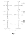
- FIG. 8 is an aberration diagram showing a lateral aberration of the imaging lens of FIG. 7 ;
- FIG. 9 is an aberration diagram showing a spherical aberration, astigmatism, and a distortion of the imaging lens of FIG. 7 ;
- FIG. 10 shows a sectional view of a schematic configuration of an imaging lens in Numerical Data Example 4 according to the embodiment of the present invention
- FIG. 11 is an aberration diagram showing a lateral aberration of the imaging lens of FIG. 10 ;
- FIG. 12 is an aberration diagram showing a spherical aberration, astigmatism, and a distortion of the imaging lens of FIG. 10 ;
- FIG. 13 shows a sectional view of a schematic configuration of an imaging lens in Numerical Data Example 5 according to the embodiment of the present invention
- FIG. 14 is an aberration diagram showing a lateral aberration of the imaging lens of FIG. 13 ;
- FIG. 15 is an aberration diagram showing a spherical aberration, astigmatism, and a distortion of the imaging lens of FIG. 13 .
- FIG. 16 shows a sectional view of a schematic configuration of an imaging lens in Numerical Data Example 6 according to the embodiment of the present invention
- FIG. 17 is an aberration diagram showing a lateral aberration of the imaging lens of FIG. 16 ;
- FIG. 18 is an aberration diagram showing a spherical aberration, astigmatism, and a distortion of the imaging lens of FIG. 16 .
- FIGS. 1, 4, 7, 10, 13, and 16 are schematic sectional views of the imaging lenses in Numerical Data Examples 1 to 6 according to the embodiment, respectively. Since the imaging lenses in those Numerical Data Examples have the same basic configuration, the lens configuration of the embodiment will be described with reference to the illustrative sectional view of Numerical Data Example 1.
- the imaging lens includes a first lens group G 1 having positive refractive power, a second lens group G 2 having positive refractive power, and a third lens group G 3 having negative refractive power, arranged in the order from an object side to an image plane side. Between the third lens group G 3 and an image plane IM of an imaging element, there is provided a filter 10 .
- the filter 10 is omissible.
- the first lens group G 1 includes a first lens L 1 having positive refractive power, an aperture stop ST, a second lens L 2 having positive refractive power, and a third lens L 3 having negative refractive power, arranged in the order from the object side.
- the aperture stop ST is provided on an image plane-side surface of the first lens L 1 .
- the position of the aperture stop ST is not limited to between the first lens L 1 and the second lens L 2 as in the imaging lens of Numerical Data Example 1.
- the aperture stop ST may be disposed on the object side of the first lens L 1 .
- the first lens L 1 is formed in a shape such that a curvature radius r 1 of an object-side surface thereof and a curvature radius r 2 of an image plane-side surface thereof are both positive, so as to have a shape of a meniscus lens directing a convex surface thereof to an object side near an optical axis X.
- the shape of the first lens L 1 is not limited to the one in Numerical Data Example 1.
- the first lens L 1 can be formed in any shape, as long as the curvature radius r 1 of the object-side surface thereof is positive.
- the first lens L 1 can also be formed in a shape such that the curvature radius r 2 is negative, so as to have a shape of a biconvex lens near the optical axis.
- the first lens L 1 is preferably formed to have a shape of a meniscus lens directing a convex surface thereof to the object side near the optical axis X.
- the second lens L 2 is formed in a shape such that a curvature radius r 3 of an object-side surface thereof is positive and a curvature radius r 4 of an image plane-side surface thereof is negative, so as to have a shape of a biconvex lens near the optical axis X.
- the third lens L 3 is formed in a shape such that a curvature radius r 5 of an object-side surface thereof and a curvature radius r 6 of an image plane-side surface thereof are both positive, so as to have a shape of a meniscus lens directing a convex surface thereof to the object side near the optical axis X.
- the shape of the third lens L 3 is not limited to the one in Numerical Data Example 1.
- the third lens can be formed in any shape, as long as the curvature radius r 6 of the image plane-side surface is positive.
- Numerical Data Examples 2 through 4 are examples, in which the third lens L 3 is formed in a shape, such that the curvature radius r 5 of the object side surface thereof is negative, i.e., so as to have a shape of a biconcave lens near the optical axis X.
- the second lens group G 2 includes a fourth lens L 4 having negative refractive power, and a fifth lens L 5 having positive refractive power, arranged in the order from the object side.
- the second lens group G 2 can be configured in any manner as long as the second lens group is composed of the two lenses and the composite refractive power of those two lenses is positive.
- Numerical Data Example 2 through 5 are examples, in which the second lens group G 2 is composed of the fourth lens L 4 having positive refractive power and the fifth lens L 5 having negative refractive power.
- Numerical Data Example 6 is an example, in which the second lens group G 2 is composed of the fourth lens L 4 and the fifth lens L 5 , which have positive refractive powers.
- the fourth lens L 4 is formed in a shape such that a curvature radius r 7 of an object-side surface thereof and a curvature radius r 8 of an image plane-side surface thereof are both negative, so as to have a shape of a meniscus lens directing a concave surface thereof to the object side near the optical axis X.
- the fifth lens L 5 is formed in a shape such that a curvature radius r 9 of an object-side surface thereof is positive and a curvature radius r 10 of an image plane-side surface thereof is negative, so as to have a shape of a biconvex lens near the optical axis X.
- the shape of the fifth lens L 5 is not limited to the one in Numerical Data Example 1.
- Numerical Data Examples 2 through 5 are examples, in which the fifth lens L 5 is formed in a shape, such that the curvature radius r 10 is positive, i.e., so as to have a shape of a meniscus lens directing a convex surface thereof to the object side near the optical axis X.
- Numerical Data Example 6 is an example, in which the fifth lens L 5 is formed in a shape, such that the curvature radius r 9 is negative, i.e., so as to have a shape of a meniscus lens directing a concave surface thereof to the object side near the optical axis X.
- the third lens group G 3 includes a sixth lens L 6 having negative refractive power, and a seventh lens L 7 having negative refractive power, arranged in the order from the object side.
- the sixth lens L 6 is formed in a shape such that a curvature radius r 11 of an object-side surface thereof and a curvature radius r 12 of an image plane-side surface thereof are both positive, so as to have a shape of a meniscus lens directing a convex surface thereof to the object side near the optical axis X.
- the seventh lens L 7 is formed in a shape such that a curvature radius r 13 of an object-side surface thereof is negative and a curvature radius r 14 of an image plane-side surface thereof is positive, so as to have a shape of a biconcave lens near the optical axis X.
- the object-side surface thereof and the image plane-side surface thereof are formed as aspheric shapes, so as to have strong positive refractive power as it goes to the periphery of the lens from the optical axis X.
- shape of the seventh lens L 7 it is achievable to satisfactorily correct off-axis chromatic aberration of magnification as well as the axial chromatic aberration.
- the shape of the seventh lens L 7 is not limited to the one in Numerical Data Example 1.
- the seventh lens L 7 can be formed in any shape, as long as the curvature radius r 14 of the image plane-side surface thereof is positive.
- Numerical Data Example 5 is an example, in which the seventh lens L 7 is formed in a shape, such that the curvature radius r 13 is positive, so as to have a shape of a meniscus lens directing a convex surface thereof to the object side near the optical axis X.
- the imaging lens satisfies the following conditional expressions (1) to (12): 40 ⁇ d 1 ⁇ 75 (1) 40 ⁇ d 2 ⁇ 75 (2) 20 ⁇ d 3 ⁇ 35 (3) 40 ⁇ d 7 ⁇ 75 (4) 2.5 ⁇ f 1/ f 2 ⁇ 30 (5) 0.5 ⁇ f 12/ f ⁇ 1.1 (6) ⁇ 1.0 ⁇ f 2/ f 3 ⁇ 0.2 (7) ⁇ 1.0 ⁇ f 12/ f 3 ⁇ 0.1 (8) ⁇ 1.5 ⁇ f 67/ f ⁇ 0.5 (9) ⁇ 3 ⁇ f 45/ f 67 ⁇ 0.8 (10) 0.02 ⁇ f 7/ f 6 ⁇ 0.3 (11) 0.03 ⁇ D 34/ f ⁇ 0.2 (12) ⁇ d1: Abbe's number of the first lens L 1 ⁇ d2: Abbe's number of the second lens L 2 ⁇ d3: Abbe's number of the third lens L 3 ⁇ d7: Abbe's number of the seventh lens L 7 f: Focal length of a whole lens system f1: Focal
- all lens surfaces are formed as an aspheric surface.
- the aspheric shapes applied to the lens surfaces have an axis Z in a direction of the optical axis X, a height H in a direction perpendicular to the optical axis X, a conic constant k, and aspheric coefficients A 4 , A 6 , A 8 , A 10 , A 12 , A 14 , and A 16 , the aspheric shapes of the lens surfaces are expressed with the following formula:
- f represents a focal length of the whole lens system
- Fno represents an F-number
- ⁇ represents a half angle of view, respectively.
- i represents a surface number counted from the object side
- r represents a curvature radius
- d represents a distance on the optical axis between lens surfaces (surface spacing)
- nd represents a refractive index
- ⁇ d represents an Abbe's number, respectively.
- aspheric surfaces are indicated with surface numbers i affixed with * (asterisk).
- the imaging lens of Numerical Data Example 1 satisfies the above-described conditional expressions.
- the distance on the optical axis X from the object-side surface of the first lens L 1 to the image plane IM (air conversion length for the filter 10 ) is 4.61 mm, and downsizing of the imaging lens is attained.
- FIG. 2 shows a lateral aberration that corresponds to a half angle of view co, which is divided into a tangential direction and a sagittal direction (The same is true for FIGS. 5, 8, 11, 14, and 17 ).
- FIG. 3 shows a spherical aberration (mm), astigmatism (mm), and a distortion (%), respectively.
- an aberration on a sagittal image surface S and an aberration on a tangential image surface T are respectively indicated (The same is true for FIGS. 6, 9, 12, 15, and 18 ).
- the aberrations are satisfactorily corrected.
- the imaging lens of Numerical Data Example 2 satisfies the above-described conditional expressions.
- the distance on the optical axis from the object-side surface of the first lens L 1 to the image plane IM (air conversion length for the filter 10 ) is 4.21 mm, and downsizing of the imaging lens is attained.
- FIG. 5 shows a lateral aberration that corresponds to the half angle of view ⁇
- FIG. 6 shows a spherical aberration (mm), astigmatism (mm), and a distortion (%), respectively, for the imaging lens of Numerical Data Example 2.
- the aberrations are also satisfactorily corrected.
- the imaging lens of Numerical Data Example 3 satisfies the above-described conditional expressions.
- the distance on the optical axis from the object-side surface of the first lens L 1 to the image plane IM (air conversion length for the filter 10 ) is 4.35 mm, and downsizing of the imaging lens is attained.
- FIG. 8 shows a lateral aberration that corresponds to the half angle of view ⁇
- FIG. 9 shows a spherical aberration (mm), astigmatism (mm), and a distortion (%), respectively, for the imaging lens of Numerical Data Example 3.
- the aberrations are also satisfactorily corrected.
- the imaging lens of Numerical Data Example 4 satisfies the above-described conditional expressions.
- the distance on the optical axis from the object-side surface of the first lens L 1 to the image plane IM (air conversion length for the filter 10 ) is 4.21 mm, and downsizing of the imaging lens is attained.
- FIG. 11 shows a lateral aberration that corresponds to the half angle of view ⁇
- FIG. 12 shows a spherical aberration (mm), astigmatism (mm), and a distortion (%), respectively, for the imaging lens of Numerical Data Example 4.
- the aberrations are also satisfactorily corrected.
- the imaging lens of Numerical Data Example 5 satisfies the above-described conditional expressions.
- the distance on the optical axis from the object-side surface of the first lens L 1 to the image plane IM (air conversion length for the filter 10 ) is 4.24 mm, and downsizing of the imaging lens is attained.
- FIG. 14 shows a lateral aberration that corresponds to the half angle of view ⁇
- FIG. 15 shows a spherical aberration (mm), astigmatism (mm), and a distortion (%), respectively, for the imaging lens of Numerical Data Example 5.
- the aberrations are also satisfactorily corrected.
- the imaging lens of Numerical Data Example 6 satisfies the above-described conditional expressions.
- the distance on the optical axis from the object-side surface of the first lens L 1 to the image plane IM (air conversion length for the filter 10 ) is 4.40 mm, and downsizing of the imaging lens is attained.
- FIG. 17 shows a lateral aberration that corresponds to the half angle of view ⁇
- FIG. 18 shows a spherical aberration (mm), astigmatism (mm), and a distortion (%), respectively, for the imaging lens of Numerical Data Example 6.
- the aberrations are also satisfactorily corrected.
- the imaging lens of the embodiment it is achievable to take an image of wide view of angle (2 ⁇ ), which is as wide as 70° or greater.
- the imaging lenses have wide angles of view of 74.0°.
- the imaging lens of the embodiment it is possible to take an image of a wider range than that can be taken by a conventional imaging lens.
- an imaging element having a high pixel count is often used in combination with a high-resolution imaging lens.
- a light-receiving area of each pixel decreases, so that an image tends to be dark.
- As a method of correcting the darkness of the image there is a method of improving light-receiving sensitivity of the imaging element by using an electrical circuit.
- the imaging lenses of Numerical Data Examples 1 to 6 the Fnos of the imaging lens are as small as 2.2 to 2.3. According to the imaging lens of the embodiment, it is achievable to obtain a sufficiently bright image without providing the above-described electrical circuit.
- the imaging lens of the embodiment is mounted in an imaging optical system, such as cameras built in portable devices including cellular phones, portable information terminals, and smartphones, digital still cameras, security cameras, onboard cameras, and network cameras, it is possible to attain both high performance and downsizing of the cameras.
- an imaging optical system such as cameras built in portable devices including cellular phones, portable information terminals, and smartphones, digital still cameras, security cameras, onboard cameras, and network cameras, it is possible to attain both high performance and downsizing of the cameras.
- the present invention may be applicable in an imaging lens to be mounted in relatively small-sized cameras such as cameras that are built in portable devices including cellular phones, smartphones, and portable information terminals, digital still cameras, security cameras, onboard cameras, and network cameras.
Abstract
Description
40<νd1<75 (1)
40<νd2<75 (2)
20<νd3<35 (3)
40<νd7<75 (4)
2.5<f1/f2<30 (5)
0.5<f12/f<1.1 (6)
−1.0<f2/f3<−0.2 (7)
−1.0<f12/f3<−0.1 (8)
−1.5<f67/f<−0.5 (9)
−3<f45/f67<−0.8 (10)
0.02<f7/f6<0.3 (11)
0.03<D34/f<0.2 (12)
40<νd1<75 (1)
40<νd2<75 (2)
20<νd3<35 (3)
40<νd7<75 (4)
2.5<f1/f2<30 (5)
0.5<f12/f<1.1 (6)
−1.0<f2/f3<−0.2 (7)
−1.0<f12/f3<−0.1 (8)
−1.5<f67/f<−0.5 (9)
−3<f45/f67<−0.8 (10)
0.02<f7/f6<0.3 (11)
0.03<D34/f<0.2 (12)
νd1: Abbe's number of the first lens L1
νd2: Abbe's number of the second lens L2
νd3: Abbe's number of the third lens L3
νd7: Abbe's number of the seventh lens L7
f: Focal length of a whole lens system
f1: Focal length of the first lens L1
f2: Focal length of the second lens L2
f3: Focal length of the third lens L3
f6: Focal length of the sixth lens L6
f7: Focal length of the seventh lens L7
f12: Composite focal length of the first lens L1 and the second lens L2
f45: Composite focal length of the fourth lens L4 and the fifth lens L5
f67: Composite focal length of the sixth lens L6 and the seventh lens L7
D34: Distance on the optical axis X between the third lens L3 and the fourth lens L4
| f = 3.44 mm, Fno = 2.2, ω = 37.0° |
| Unit: mm |
| Surface Data |
| Surface | ||||
| Number i | r | d | nd | νd |
| (Object) | ∞ | ∞ | ||
| 1* | 2.255 | 0.317 | 1.5346 | 56.1 (=νd1) |
| 2* (Stop) | 2.436 | 0.065 | ||
| 3* | 2.400 | 0.500 | 1.5346 | 56.1 (=νd2) |
| 4* | −8.336 | 0.071 | ||
| 5* | 5.370 | 0.250 | 1.6355 | 24.0 (=νd3) |
| 6* | 2.997 | 0.436 (=D34) | ||
| 7* | −1.358 | 0.315 | 1.5346 | 56.1 (=νd4) |
| 8* | −1.506 | 0.048 | ||
| 9* | 57.269 | 0.557 | 1.5346 | 56.1 (=νd5) |
| 10* | −1.579 | 0.072 | ||
| 11* | 6.586 | 0.390 | 1.6355 | 24.0 (=νd6) |
| 12* | 5.835 | 0.197 | ||
| 13* | −3.293 | 0.359 | 1.5346 | 56.1 (=νd7) |
| 14* | 2.281 | 0.300 | ||
| 15 | ∞ | 0.200 | 1.5168 | 64.2 |
| 16 | ∞ | 0.601 | ||
| (Image plane) | ∞ | |||
| Aspheric Surface Data |
| First Surface |
| k = 0.000, A4 = −1.114E−01, A6 = 1.716E−01, A8 = −6.753E−01, |
| A10 = 9.113E−01, A12 = −4.349E−01, A14 = −1.715E−01, |
| A16 = 2.030E−01 |
| Second Surface |
| k = 0.000, A4 = −2.098E−01, A6 = 4.528E−01, A8 = −3.217, |
| A10 = 6.995, A12 = −4.687, A14 = −2.463, A16 = 3.568 |
| Third Surface |
| k = 0.000, A4 = −4.970E−02, A6 = −1.500E−01, A8 = −7.221E−01, |
| A10 = 1.724, A12 = −6.829E−01, A14 = −6.475E−01, A16 = 6.175E−01 |
| Fourth Surface |
| k = 0.000, A4 = −2.271E−01, A6 = −7.422E−02, A8 = 3.681E−02, |
| A10 = 4.386E−01, A12 = −6.822E−01, A14 = 3.633E−01, |
| A16 = 1.075E−01 |
| Fifth Surface |
| k = 0.000, A4 = −2.983E−01, A6 = −5.158E−01, A8 = 1.744, |
| A10 = −2.258, A12 = 1.053, A14 = 8.637E−01, A16 = −7.917E−01 |
| Sixth Surface |
| k = 0.000, A4 = −7.205E−02, A6 = −4.150E−01, A8 = 1.298, |
| A10 = −1.771, A12 = 8.587E−01, A14 = 2.137E−01, A16 = −2.201E−01 |
| Seventh Surface |
| k = 0.000, A4 = 2.681E−01, A6 = −2.030E−01, A8 = 2.977E−01, |
| A10 = 5.153E−02, A12 = −5.830E−01, A14 = 3.652E−01, |
| A16 = −1.807E−02 |
| Eighth Surface |
| k = 0.000, A4 = 1.636E−01, A6 = −1.044E−01, A8 = 1.139E−01, |
| A10 = −4.936E−02, A12 = 4.089E−03, A14 = −5.458E−03, |
| A16 = 7.198E−03 |
| Ninth Surface |
| k = 0.000, A4 = −2.036E−02, A6 = 1.008E−01, A8 = −9.426E−02, |
| A10 = 3.535E−02, A12 = 4.329E−03, A14 = −6.757E−03, |
| A16 = 8.930E−04 |
| Tenth Surface |
| k = 0.000, A4 = 9.355E−02, A6 = 6.215E−02, A8 = 7.676E−03, |
| A10 = −9.918E−03, A12 = −4.698E−04, A14 = −2.538E−04, |
| A16 = 2.680E−04 |
| Eleventh Surface |
| k = 0.000, A4 = −9.058E−02, A6 = 1.506E−02, A8 = −7.881E−03, |
| A10 = 7.829E−03, A12 = −5.240E−04, A14 = −3.709E−04, |
| A16 = −1.445E−04 |
| Twelfth Surface |
| k = 0.000, A4 = −1.402E−01, A6 = 4.012E−02, A8 = 1.525E−03, |
| A10 = −2.457E−03, A12 = −1.461E−05, A14 = 1.635E−04, |
| A16 = −3.523E−05 |
| Thirteenth Surface |
| k = 0.000, A4 = −6.802E−02, A6 = 1.037E−01, A8 = −4.345E−02, |
| A10 = 1.099E−02, A12 = −3.796E−03, A14 = 1.273E−03, |
| A16 = −1.683E−04 |
| Fourteenth Surface |
| k = 0.000, A4 = −1.616E−01, A6 = 1.157E−01, A8 = −6.605E−02, |
| A10 = 2.465E−02, A12 = −5.885E−03, A14 = 8.025E−04, |
| A16 = −4.741E−05 |
| f1 = 35.25 mm | |
| f2 = 3.54 mm | |
| f3 = −11.13 mm | |
| f4 = −99.63 mm | |
| f5 = 2.88 mm | |
| f6 = −100.83 mm | |
| f7 = −2.47 mm | |
| f12 = 3.38 mm | |
| f45 = 2.73 mm | |
| f67 = −2.45 mm | |
| The values of the respective conditional expressions are as follows: |
| f1/f2 = 9.95 | |
| f12/f = 0. 98 | |
| f2/f3 = −0.32 | |
| f12/f3 = −0.30 | |
| f67/f = −0.71 | |
| f45/f67 = −1.113 | |
| f7/f6 = 0.024 | |
| D34/f = 0.13 | |
| f = 3.37 mm, Fno = 2.2, ω = 37.0° |
| Unit: mm |
| Surface Data |
| Surface | ||||
| Number i | r | d | nd | νd |
| (Object) | ∞ | ∞ | ||
| 1* | 1.687 | 0.360 | 1.5346 | 56.1 (=νd1) |
| 2* (Stop) | 2.080 | 0.081 | ||
| 3* | 2.069 | 0.627 | 1.5346 | 56.1 (=νd2) |
| 4* | −2.335 | 0.012 | ||
| 5* | −12.711 | 0.250 | 1.6355 | 24.0 (=νd3) |
| 6* | 2.963 | 0.337 (=D34) | ||
| 7* | −1.851 | 0.511 | 1.5346 | 56.1 (=νd4) |
| 8* | −1.255 | 0.036 | ||
| 9* | 14.291 | 0.415 | 1.6355 | 24.0 (=νd5) |
| 10* | 11.555 | 0.060 | ||
| 11* | 5.140 | 0.303 | 1.5346 | 56.1 (=νd6) |
| 12* | 3.728 | 0.151 | ||
| 13* | −9.215 | 0.292 | 1.5346 | 56.1 (=νd7) |
| 14* | 2.376 | 0.140 | ||
| 15 | ∞ | 0.200 | 1.5168 | 64.2 |
| 16 | ∞ | 0.501 | ||
| (Image plane) | ∞ | |||
| Aspheric Surface Data |
| First Surface |
| k = 0.000, A4 = −1.035E−01, A6 = 1.546E−01, A8 = −6.963E−01, |
| A10 = 8.976E−01, A12 = −4.726E−01, A14 = −1.734E−01, |
| A16 = 2.316E−01 |
| Second Surface |
| k = 0.000, A4 = −2.430E−01, A6 = 3.610E−01, A8 = −3.129, |
| A10 = 7.060, A12 = −4.768, A14 = −2.712, A16 = 3.926 |
| Third Surface |
| k = 0.000, A4 = −1.037E−01, A6 = −2.199E−01, A8 = −6.181E−01, |
| A10 = 1.739, A12 = −6.029E−01, A14 = −5.764E−01, A16 = 4.109E−01 |
| Fourth Surface |
| k = 0.000, A4 = −1.993E−01, A6 = 1.142E−02, A8 = 4.385E−02, |
| A10 = 5.225E−01, A12 = −7.827E−01, A14 = 1.273E−02, |
| A16 = 4.693E−01 |
| Fifth Surface |
| k = 0.000, A4 = −2.463E−01, A6 = −5.153E−01, A8 = 1.901, |
| A10 = −2.250, A12 = 7.890E−01, A14 = 7.249E−01, A16 = −4.881E−01 |
| Sixth Surface |
| k = 0.000, A4 = −9.455E−03, A6 = −4.924E−01, A8 = 1.270, |
| A10 = −1.695, A12 = 8.868E−01, A14 = 9.271E−02, A16 = −1.255E−01 |
| Seventh Surface |
| k = 0.000, A4 = 2.488E−01, A6 = −9.798E−02, A8 = 1.387E−01, |
| A10 = −5.087E−02, A12 = −4.688E−01, A14 = 4.874E−01, |
| A16 = −1.679E−01 |
| Eighth Surface |
| k = 0.000, A4 = 1.703E−01, A6 = 6.899E−02, A8 = 1.171E−01, |
| A10 = −6.243E−02, A12 = −1.388E−02, A14 = −3.738E−03, |
| A16 = 7.153E−03 |
| Ninth Surface |
| k = 0.000, A4 = −1.639E−01, A6 = 1.073E−01, A8 = −8.969E−02, |
| A10 = 9.542E−03, A12 = −4.894E−03, A14 = −4.582E−03, |
| A16 = 4.992E−03 |
| Tenth Surface |
| k = 0.000, A4 = −1.500E−01, A6 = 5.422E−02, A8 = −2.166E−02, |
| A10 = −9.624E−03, A12 = 1.901E−03, A14 = 7.129E−04, |
| A16 = 6.232E−04 |
| Eleventh Surface |
| k = 0.000, A4 = −2.030E−01, A6 = 2.297E−03, A8 = 2.201E−02, |
| A10 = 2.780E−04, A12 = 6.385E−04, A14 = −7.657E−05, |
| A16 = −2.699E−04 |
| Twelfth Surface |
| k = 0.000, A4 = −1.577E−01, A6 = 2.996E−02, A8 = 2.442E−03, |
| A10 = −2.418E−03, A12 = −2.139E−04, A14 = 1.344E−04, |
| A16 = 1.979E−05 |
| Thirteenth Surface |
| k = 0.000, A4 = −9.538E−02, A6 = 9.840E−02, A8 = −4.715E−02, |
| A10 = 1.099E−02, A12 = −3.581E−03, A14 = 1.355E−03, |
| A16 = −1.798E−04 |
| Fourteenth Surface |
| k = 0.000, A4 = −2.024E−01, A6 = 1.307E−01, A8 = −6.820E−02, |
| A10 = 2.474E−02, A12 = −5.882E−03, A14 = 7.922E−04, |
| A16 = −4.563E−05 |
| f1 = 12.65 mm | |
| f2 = 2.16 mm | |
| f3 = −3.76 mm | |
| f4 = 5.61 mm | |
| f5 = −100.94 mm | |
| f6 = −27.45 mm | |
| f7 = −3.50 mm | |
| f12 = 2.01 mm | |
| f45 = 5.88 mm | |
| f67 = −3.13 mm | |
| The values of the respective conditional expressions are as follows: |
| f1/f2 = 5.86 | |
| f12/f = 0.60 | |
| f2/f3 = −0.57 | |
| f12/f3 = −0.54 | |
| f67/f = −0.93 | |
| f45/f67 = −1.88 | |
| f7/f6 = 0.13 | |
| D34/f = 0.10 | |
| f = 3.37 mm, Fno = 2.3, ω = 37.0° |
| Unit: mm |
| Surface Data |
| Surface | ||||
| Number i | r | d | nd | νd |
| (Object) | ∞ | ∞ | ||
| 1* | 1.680 | 0.386 | 1.5346 | 56.1 (=νd1) |
| 2* (Stop) | 2.599 | 0.104 | ||
| 3* | 3.000 | 0. 626 | 1.5346 | 56.1 (=νd2) |
| 4* | −1.962 | 0.078 | ||
| 5* | −3.345 | 0.250 | 1.6355 | 24.0 (=νd3) |
| 6* | 2.882 | 0.238 (=D34) | ||
| 7* | −2.871 | 0.452 | 1.5346 | 56.1 (=νd4) |
| 8* | −1.267 | 0.050 | ||
| 9* | 11.980 | 0.486 | 1.6355 | 24.0 (=νd5) |
| 10* | 9.931 | 0.170 | ||
| 11* | 4.056 | 0.300 | 1.5346 | 56.1 (=νd6) |
| 12* | 3.372 | 0.157 | ||
| 13* | −23.911 | 0.310 | 1.5346 | 56.1 (=νd7) |
| 14* | 2.380 | 0.200 | ||
| 15 | ∞ | 0.200 | 1.5168 | 64.2 |
| ∞ | 0.414 | |||
| (Image plane) | ∞ | |||
| Aspheric Surface Data |
| First Surface |
| k = 0.000, A4 = −8.241E−02, A6 = 1.518E−01, A8 = −6.952E−01, |
| A10 = 8.909E−01, A12 = −4.931E−01, A14 = −1.811E−01, |
| A16 = 2.666E−01 |
| Second Surface |
| k = 0.000, A4 = −2.275E−01, A6 = 3.836E−01, A8 = −3.017, |
| A10 = 6.945, A12 = −4.983, A14 = −2.666, A16 = 4.176 |
| Third Surface |
| k = 0.000, A4 = −1.432E−01, A6 = −1.337E−01, A8 = −6.040E−01, |
| A10 = 1.794, A12 = −6.104E−01, A14 = −7.571E−01, A16 = 2.584E−01 |
| Fourth Surface |
| k = 0.000, A4 = −1.073E−01, A6 = −5.463E−02, A8 = −4.255E−03, |
| A10 = 5.463E−01, A12 = −6.893E−01, A14 = −1.210E−02, |
| A16 = 1.850E−01 |
| Fifth Surface |
| k = 0.000, A4 = −2.576E−01, A6 = −4.667E−01, A8 = 1.903, |
| A10 = −2.336, A12 = 6.689E−01, A14 = 7.776E−01, A16 = −4.608E−01 |
| Sixth Surface |
| k = 0.000, A4 = −7.944E−02, A6 = −4.418E−01, A8 = 1.276, |
| A10 = −1.711, A12 = 8.974E−01, A14 = 6.691E−02, A16 = −1.087E−01 |
| Seventh Surface |
| k = 0.000, A4 = 2.513E−01, A6 = −1.421E−01, A8 = 1.263E−01, |
| A10 = −1.827E−02, A12 = −4.186E−01, A14 = 5.029E−01, |
| A16 = −1.843E−01 |
| Eighth Surface |
| k = 0.000, A4 = 1.919E−01, A6 = 7.248E−02, A8 = 1.153E−01, |
| A10 = −6.760E−02, A12 = −2.090E−02, A14 = −5.478E−03, |
| A16 = 9.951E−03 |
| Ninth Surface |
| k = 0.000, A4 = −1.001E−01, A6 = 9.987E−02, A8 = −9.297E−02, |
| A10 = 1.434E−02, A12 = 1.058E−05, A14 = −2.628E−03, |
| A16 = 2.872E−03 |
| Tenth Surface |
| k = 0.000, A4 = −1.569E−01, A6 = 5.735E−02, A8 = −1.942E−02, |
| A10 = −9.047E−03, A12 = 1.646E−03, A14 = 4.727E−04, |
| A16 = 5.869E−04 |
| Eleventh Surface |
| k = 0.000, A4 = −2.248E−01, A6 = 1.366E−03, A8 = 2.158E−02, |
| A10 = 1.515E−04, A12 = 6.444E−04, A14 = −3.185E−05, |
| A16 = −2.051E−04 |
| Twelfth Surface |
| k = 0.000, A4 = −1.554E−01, A6 = 2.774E−02, A8 = 2.233E−03, |
| A10 = −2.424E−03, A12 = −2.127E−04, A14 = 1.357E−04, |
| A16 = 1.991E−05 |
| Thirteenth Surface |
| k = 0.000, A4 = −1.038E−01, A6 = 9.883E−02, A8 = −4.721E−02, |
| A10 = 1.096E−02, A12 = −3.591E−03, A14 = 1.353E−03, |
| A16 = −1.801E−04 |
| Fourteenth Surface |
| k = 0.000, A4 = −1.990E−01, A6 = 1.305E−01, A8 = −6.810E−02, |
| A10 = 2.478E−02, A12 = −5.877E−03, A14 = 7.925E−04, |
| A16 = −4.580E−05 |
| f1 = 7.75 mm | |
| f2 = 2.32 mm | |
| f3 = −2.40 mm | |
| f4 = 3.86 mm | |
| f5 = −100.64 mm | |
| f6 = −44.16 mm | |
| f7 = −4.03 mm | |
| f12 = 1.98 mm | |
| f45 = 3.95 mm | |
| f67 = −3.76 mm | |
| The values of the respective conditional expressions are as follows: |
| f1/f2 = 3.34 | |
| f12/f = 0.59 | |
| f2/f3 = −0.97 | |
| f12/f3 = −0.83 | |
| f67/f = −1.11 | |
| f45/f67 = −1.05 | |
| f7/f6 = 0.091 | |
| D34/f = 0.070 | |
| f = 3.37 mm, Fno = 2.2, ω = 37.0° |
| Unit: mm |
| Surface Data |
| Surface | ||||
| Number i | r | d | nd | νd |
| (Object) | ∞ | ∞ | ||
| 1* | 1.740 | 0.353 | 1.5346 | 56.1 (=νd1) |
| 2* (Stop) | 2.078 | 0.074 | ||
| 3* | 2.105 | 0.642 | 1.5346 | 56.1 (=νd2) |
| 4* | −2.421 | 0.021 | ||
| 5* | −17.903 | 0.250 | 1.6355 | 24.0 (=νd3) |
| 6* | 3.540 | 0.331 (=D34) | ||
| 7* | −1.594 | 0.450 | 1.5346 | 56.1 (=νd4) |
| 8* | −1.251 | 0.058 | ||
| 9* | 11.093 | 0.445 | 1.6355 | 24.0 (=νd5) |
| 10* | 6.053 | 0.070 | ||
| 11* | 4.217 | 0.319 | 1.5346 | 56.1 (=νd6) |
| 12* | 3.806 | 0.129 | ||
| 13* | −25.224 | 0.292 | 1.5346 | 56.1 (=νd7) |
| 14* | 2.369 | 0.140 | ||
| 15 | ∞ | 0.200 | 1.5168 | 64.2 |
| 16 | ∞ | 0.501 | ||
| (Image plane) | ∞ | |||
| Aspheric Surface Data |
| First Surface |
| k = 0.000, A4 = −1.059E−01, A6 = 1.519E−01, A8 = −6.957E−01, |
| A10 = 9.014E−01, A12 = −4.692E−01, A14 = −1.711E−01, |
| A16 = 2.338E−01 |
| Second Surface |
| k = 0.000, A4 = −2.420E−01, A6 = 3.601E−01, A8 = −3.128, |
| A10 = 7.058, A12 = −4.769, A14 = −2.705, A16 = 3.941 |
| Third Surface |
| k = 0.000, A4 = −1.054E−01, A6 = −2.159E−01, A8 = −6.197E−01, |
| A10 = 1.737, A12 = −5.978E−01, A14 = −5.618E−01, A16 = 4.096E−01 |
| Fourth Surface |
| k = 0.000, A4 = −1.990E−01, A6 = 1.660E−02, A8 = 5.257E−02, |
| A10 = 5.262E−01, A12 = −7.864E−01, A14 = 7.137E−03, |
| A16 = 4.777E−01 |
| Fifth Surface |
| k = 0.000, A4 = −2.303E−01, A6 = −5.051E−01, A8 = 1.902, |
| A10 = −2.253, A12 = 7.865E−01, A14 = 7.259E−01, A16 = −4.857E−01 |
| Sixth Surface |
| k = 0.000, A4 = −1.269E−02, A6 = −4.889E−01, A8 = 1.274, |
| A10 = −1.695, A12 = 8.861E−01, A14 = 8.995E−02, A16 = −1.334E−01 |
| Seventh Surface |
| k = 0.000, A4 = 2.686E−01, A6 = −8.696E−02, A8 = 1.475E−01, |
| A10 = −4.466E−02, A12 = −4.663E−01, A14 = 4.854E−01, |
| A16 = −1.752E−01 |
| Eighth Surface |
| k = 0.000, A4 = 1.760E−01, A6 = 7.701E−02, A8 = 1.205E−01, |
| A10 = −6.102E−02, A12 = −1.408E−02, A14 = −5.581E−03, |
| A16 = 3.934E−03 |
| Ninth Surface |
| k = 0.000, A4 = −1.778E−01, A6 = 1.010E−01, A8 = −9.084E−02, |
| A10 = 4.372E−03, A12 = −1.141E−02, A14 = −7.648E−03, |
| A16 = 8.843E−03 |
| Tenth Surface |
| k = 0.000, A4 = −1.619E−01, A6 = 4.960E−02, A8 = −2.249E−02, |
| A10 = −9.490E−03, A12 = 2.128E−03, A14 = 8.518E−04, |
| A16 = 6.754E−04 |
| Eleventh Surface |
| k = 0.000, A4 = −2.120E−01, A6 = 2.271E−03, A8 = 2.202E−02, |
| A10 = 2.240E−04, A12 = 6.022E−04, A14 = −9.079E−05, |
| A16 = −2.710E−04 |
| Twelfth Surface |
| k = 0.000, A4 = −1.486E−01, A6 = 2.966E−02, A8 = 2.301E−03, |
| A10 = −2.471E−03, A12 = −2.360E−04, A14 = 1.248E−04, |
| A16 =1.563E−05 |
| Thirteenth Surface |
| k = 0.000, A4 = −1.016E−01, A6 = 9.787E−02, A8 = −4.729E−02, |
| A10 = 1.095E−02, A12 = −3.587E−03, A14 = 1.356E−03, |
| A16 = − 1.785E−04 |
| Fourteenth Surface |
| k = 0.000, A4 = −2.040E−01, A6 = 1.305E−01, A8 = −6.819E−02, |
| A10 = 2.475E−02, A12 = −5.881E−03, A14 = 7.921E−04, |
| A16 = −4.569E−05 |
| f1 = 14.67 mm | |
| f2 = 2.22 mm | |
| f3 = −4.63 mm | |
| f4 = 7.46 mm | |
| f5 = −21.71 mm | |
| f6 = −100.33 mm | |
| f7 = −4.04 mm | |
| f12 = 2.09 mm | |
| f45 = 11.40 mm | |
| f67 = −3.97 mm | |
| The values of the respective conditional expressions are as follows: |
| f1/f2 = 6.62 | |
| f12/f = 0.62 | |
| f2/f3 = −0.48 | |
| f12/f3 = −0.45 | |
| f67/f = −1.18 | |
| f45/f67 = −2.87 | |
| f7/f6 = 0.040 | |
| D34/f = 0.098 | |
| f = 3.33 mm, Fno = 2.2, ω = 37.0° |
| Unit: mm |
| Surface Data |
| Surface | ||||
| Number i | r | d | nd | νd |
| (Object) | ∞ | ∞ | ||
| 1* | 1.998 | 0.312 | 1.5346 | 56.1 (=νd1) |
| 2* (Stop) | 2.029 | 0.079 | ||
| 3* | 2.212 | 0.529 | 1.5346 | 56.1 (=νd2) |
| 4* | −3.987 | 0.031 | ||
| 5* | 12.215 | 0.250 | 1.6355 | 24.0 (=νd3) |
| 6* | 3.749 | 0.629 (=D34) | ||
| 7* | −2.154 | 0.407 | 1.5346 | 56.1 (=νd4) |
| 8* | −1.267 | 0.039 | ||
| 9* | 5.866 | 0.333 | 1.6355 | 24.0 (=νd5) |
| 10* | 5.255 | 0.060 | ||
| 11* | 3.137 | 0.298 | 1.5346 | 56.1 (=νd6) |
| 12* | 2.173 | 0.193 | ||
| 13* | 11397.590 | 0.297 | 1.5346 | 56.1 (=νd7) |
| 14* | 2.258 | 0.200 | ||
| 15 | ∞ | 0.200 | 1.5168 | 64.2 |
| 16 | ∞ | 0.447 | ||
| (Image plane) | ∞ | |||
| Aspheric Surface Data |
| First Surface |
| k = 0.000, A4 = −1.273E−01, A6 = 1.508E−01, A8 = −6.904E−01, |
| A10 = 9.804E−01, A12 = −4.571E−01, A14 = −1.739E−01, |
| A16 = 1.781E−01 |
| Second Surface |
| k = 0.000, A4 = −2.502E−01, A6 = 3.963E−01, A8 = −3.044, |
| A10 = 7.055, A12 = −4.876, A14 = −2.735, A16 = 4.031 |
| Third Surface |
| k = 0.000, A4 = −8.921E−02, A6 = −1.497E−01, A8 = −6.485E−01, |
| A10 = 1.685, A12 = −5.815E−01, A14 = −4.625E−01, A16 = 1.919E−01 |
| Fourth Surface |
| k = 0.000, A4 = −2.203E−01, A6 = −1.224E−02, A8 = 3.919E−02, |
| A10 = 5.267E−01, A12 = −7.603E−01, A14 = 4.830E−02, |
| A16 = 3.557E−01 |
| Fifth Surface |
| k = 0.000, A4 = −2.164E−01, A6 = −5.134E−01, A8 = 1.864, |
| A10 = −2.257, A12 = 7.562E−01, A14 = 7.189E−01, A16 = −4.850E−01 |
| Sixth Surface |
| k = 0.000, A4 = −2.237E−02, A6 = −4.625E−01, A8 = 1.272, |
| A10 = −1.689, A12 = 9.042E−01, A14 = 8.765E−02, A16 = −1.767E−01 |
| Seventh Surface |
| k = 0.000, A4 = 1.892E−01, A6 = −8.488E−02, A8 = 1.915E−01, |
| A10 = −6.353E−03, A12 = −4.467E−01, A14 = 4.821E−01, |
| A16 = −1.720E−01 |
| Eighth Surface |
| k = 0.000, A4 = 1.858E−01, A6 = 5.304E−02, A8 = 1.167E−01, |
| A10 = −6.230E−02, A12 = −1.436E−02, A14 = −1.115E−03, |
| A16 = 5.918E−03 |
| Ninth Surface |
| k = 0.000, A4 = −1.667E−01, A6 = 1.096E−01, A8 = −8.725E−02, |
| A10 = 1.457E−02, A12 = −4.883E−03, A14 = −7.030E−03, |
| A16 = 4.503E−03 |
| Tenth Surface |
| k = 0.000, A4 = −1.637E−01, A6 = 6.542E−02, A8 = −2.581E−02, |
| A10 = −1.078E−02, A12 = 2.408E−03, A14 = 1.127E−03, |
| A16 = 4.300E−04 |
| Eleventh Surface |
| k = 0.000, A4 = −2.019E−01, A6 = −3.117E−03, A8 = 2.040E−02, |
| A10 = −7.931E−05, A12 = 4.201E−04, A14 = −7.934E−05, |
| A16 = −1.698E−04 |
| Twelfth Surface |
| k = 0.000, A4 = −1.885E−01, A6 = 3.279E−02, A8 = 1.241E−03, |
| A10 = −2.764E−03, A12 = −2.670E−04, A14 = 1.320E−04, |
| A16 = 2.895E−05 |
| Thirteenth Surface |
| k = 0.000, A4 = −1.080E−01, A6 = 9.773E−02, A8 = −4.668E−02, |
| A10 = 1.088E−02, A12 = −3.651E−03, A14 = 1.346E−03, |
| A16 = −1.710E−04 |
| Fourteenth Surface |
| k = 0.000, A4 = −2.023E−01, A6 = 1.308E−01, A8 = −6.847E−02, |
| A10 = 2.473E−02, A12 = −5.880E−03, A14 = 7.920E−04, |
| A16 = −4.567E−05 |
| f1 = 54.33 mm | |
| f2 = 2.74 mm | |
| f3 = −8.61 mm | |
| f4 = 4.96 mm | |
| f5 = −100.82 mm | |
| f6 = −14.82 mm | |
| f7 = −4.23 mm | |
| f12 = 2.76 mm | |
| f45 = 5.10 mm | |
| f67 = −3.31 mm | |
| The values of the respective conditional expressions are as follows: |
| fl/f2 = 19.81 | |
| f12/f = 0.83 | |
| f2/f3 = −0.32 | |
| f12/f3 = −0.32 | |
| f67/f = −0.99 | |
| f45/f67 = −1.54 | |
| f7/f6 = 0.29 | |
| D34/f = 0.19 | |
| f = 3.37 mm, Fno = 2.2, ω = 37.0° |
| Unit: mm |
| Surface Data |
| Surface | ||||
| Number i | r | d | nd | νd |
| (Object) | ∞ | ∞ | ||
| 1* | 1.754 | 0.343 | 1.5346 | 56.1 (=νd1) |
| 2* (Stop) | 1.779 | 0.096 | ||
| 3* | 2.057 | 0.500 | 1.5346 | 56.1 (=νd2) |
| 4* | −5.203 | 0.030 | ||
| 5* | 8.410 | 0.250 | 1.6355 | 24.0 (=νd3) |
| 6* | 3.200 | 0.403 (=D34) | ||
| 7* | −1.580 | 0.346 | 1.5346 | 56.1 (=νd4) |
| 8* | −1.643 | 0.047 | ||
| 9* | −10.498 | 0.470 | 1.5346 | 56.1 (=νd5) |
| 10* | −1.513 | 0.060 | ||
| 11* | 5.245 | 0.342 | 1.6355 | 24.0 (=νd6) |
| 12* | 4.341 | 0.168 | ||
| 13* | −3.342 | 0.365 | 1.5346 | 56.1 (=νd7) |
| 14* | 2.330 | 0.250 | ||
| 15 | ∞ | 0.200 | 1.5168 | 64.2 |
| 16 | ∞ | 0.597 | ||
| (Image plane) | ∞ | |||
| Aspheric Surface Data |
| First Surface |
| k = 0.000, A4 = −1.251E−01, A6 = 1.669E−01, A8 = −6.668E−01, |
| A10 = 9.053E−01, A12 = −5.258E−01, A14 = −1.012E−01, |
| A16 = 1.986E−01 |
| Second Surface |
| k = 0.000, A4 = −3.204E−01, A6 = 4.458E−01, A8 = −3.063, |
| A10 = 6.788, A12 = −5.061, A14 = −1.504, A16 = 2.998 |
| Third Surface |
| k = 0.000, A4 = −1.540E−01, A6 = −1.263E−01, A8 = −7.686E−01, |
| A10 = 1.771, A12 = −6.823E−01, A14 = −1.560E−01, |
| A16 = −3.715E−02 |
| Fourth Surface |
| k = 0.000, A4 = −2.584E−01, A6 = −2.428E−02, A8 = 1.690E−01, |
| A10 = 3.337E−01, A12 = −7.684E−01, A14 = 3.283E−01, |
| A16 = 1.218E−01 |
| Fifth Surface |
| k = 0.000, A4 = −2.665E−01, A6 = −4.280E−01, A8 = 1.683, |
| A10 = −2.114, A12 = 5.449E−01, A14 = 1.011, |
| A16 = −5.988E−01 |
| Sixth Surface |
| k = 0.000, A4 = −2.117E−02, A6 = −4.541E−01, A8 = 1.283, |
| A10 = −1.782, A12 = 9.159E−01, A14 = 1.749E−01, |
| A16 = −2.109E−01 |
| Seventh Surface |
| k = 0.000, A4 = 1.878E−01, A6 = −2.029E−01, A8 = 3.026E−01, |
| A10 = 4.645E−02, A12 = −5.625E−01, A14 = 3.660E−01, |
| A16 = −2.208E−02 |
| Eighth Surface |
| k = 0.000, A4 = 1.055E−01, A6 = −1.020E−01, A8 = 9.764E−02, |
| A10 = −3.036E−02, A12 = 1.045E−05, A14 = 6.110E−04, |
| A16 = 7.310E−03 |
| Ninth Surface |
| k = 0.000, A4 = −1.538E−02, A6 = 9.087E−02, A8 = −1.159E−01, |
| A10 = 4.385E−02, A12 = 4.559E−03, A14 = −6.675E−03, |
| A16 = 2.121E−04 |
| Tenth Surface |
| k = 0.000, A4 = 1.028E−01, A6 = 5.866E−02, A8 = 1.504E−02, |
| A10 = −1.355E−02, A12 = −1.586E−03, A14 = 3.238E−04, |
| A16 = 1.121E−04 |
| Eleventh Surface |
| k = 0.000, A4 = −1.681E−01, A6 = 1.559E−02, A8 = −2.368E−03, |
| A10 = 1.331E−02, A12 = −5.693E−04, A14 = −1.351E−03, |
| A16 = −1.707E−04 |
| Twelfth Surface |
| k = 0.000, A4 = −2.149E−01, A6 = 5.930E−02, A8 = 1.207E−03, |
| A10 = −3.015E−03, A12 = 2.723E−04, A14 = 1.587E−04, |
| A16 = −3.731E−05 |
| Thirteenth Surface |
| k = 0.000, A4 = −6.768E−02, A6 = 9.771E−02, A8 = −3.986E−02, |
| A10 = 1.101E−02, A12 = −3.971E−03, A14 = 1.268E−03, |
| A16 = −1.682E−04 |
| Fourteenth Surface |
| k = 0.000, A4 = −1.604E−01, A6 = 1.128E−01, A8 = −6.563E−02, |
| A10 = 2.480E−02, A12 = −5.899E−03, A14 = 7.955E−04, |
| A16 = −4.663E−05 |
| f1 = 40.46 mm | |
| f2 = 2.83 mm | |
| f3 = −8.28 mm | |
| f4 = 84.01 mm | |
| f5 = 3.25 mm | |
| f6 = −46.45 mm | |
| f7 = −2.51 mm | |
| f12 = 2.83 mm | |
| f45 = 2.93 mm | |
| f67 = −2.43 mm | |
| The values of the respective conditional expressions are as follows: |
| f1/f2 = 14.32 | |
| f12/f = 0.84 | |
| f2/f3 = −0.34 | |
| f12/f3 = −0.34 | |
| f67/f = −0.72 | |
| f45/f67 = −1.21 | |
| f7/f6 = 0.054 | |
| D34/f = 0.12 | |
Claims (19)
0.02<f7/f6<0.3,
40<νd7<75.
40<νd1<75,
40<νd2<75,
20<νd3<35.
2.5<f1/f2<30.
0.5<f12/f<1.1,
−1.0<f2/f3<−0.2.
−1.0<f12/f3<−0.1.
−1.5<f67/f<−0.5,
−3<f45/f67<−0.8.
0.03<D34/f<0.2
0.03<D34/f<0.2
40<νd1<75,
40<νd2<75,
20<νd3<35.
40<νd7<75.
2.5<f1/f2<30.
0.5<f12/f<1.1.
−1.0<f2/f3<−0.2.
−1.0<f12/f3<−0.1.
−1.5<f67/f<−0.5.
−3<f45/f67<−0.8.
0.02<f7/f6<0.3.
Priority Applications (1)
| Application Number | Priority Date | Filing Date | Title |
|---|---|---|---|
| US15/925,992 US10481364B2 (en) | 2014-04-15 | 2018-03-20 | Imaging lens |
Applications Claiming Priority (5)
| Application Number | Priority Date | Filing Date | Title |
|---|---|---|---|
| JP2014083530A JP6278354B2 (en) | 2014-04-15 | 2014-04-15 | Imaging lens |
| JP2014-083530 | 2014-04-15 | ||
| PCT/JP2015/060481 WO2015159721A1 (en) | 2014-04-15 | 2015-04-02 | Image capture lens |
| US15/260,399 US10067313B2 (en) | 2014-04-15 | 2016-09-09 | Imaging lens |
| US15/925,992 US10481364B2 (en) | 2014-04-15 | 2018-03-20 | Imaging lens |
Related Parent Applications (1)
| Application Number | Title | Priority Date | Filing Date |
|---|---|---|---|
| US15/260,399 Continuation US10067313B2 (en) | 2014-04-15 | 2016-09-09 | Imaging lens |
Publications (2)
| Publication Number | Publication Date |
|---|---|
| US20180210169A1 US20180210169A1 (en) | 2018-07-26 |
| US10481364B2 true US10481364B2 (en) | 2019-11-19 |
Family
ID=54323933
Family Applications (12)
| Application Number | Title | Priority Date | Filing Date |
|---|---|---|---|
| US15/260,399 Active 2035-05-17 US10067313B2 (en) | 2014-04-15 | 2016-09-09 | Imaging lens |
| US15/925,992 Active US10481364B2 (en) | 2014-04-15 | 2018-03-20 | Imaging lens |
| US15/925,903 Active US10466441B2 (en) | 2014-04-15 | 2018-03-20 | Imaging lens |
| US15/925,936 Active US10473891B2 (en) | 2014-04-15 | 2018-03-20 | Imaging lens |
| US16/445,759 Active 2035-09-09 US11092777B2 (en) | 2014-04-15 | 2019-06-19 | Imaging lens |
| US16/445,797 Active 2035-09-16 US11086102B2 (en) | 2014-04-15 | 2019-06-19 | Imaging lens |
| US16/446,738 Active 2035-09-25 US11022780B2 (en) | 2014-04-15 | 2019-06-20 | Imaging lens |
| US16/446,701 Active 2035-09-23 US11099356B2 (en) | 2014-04-15 | 2019-06-20 | Imaging lens |
| US17/109,417 Active 2035-07-19 US11668903B2 (en) | 2014-04-15 | 2020-12-02 | Imaging lens |
| US17/109,451 Active 2035-07-15 US11668904B2 (en) | 2014-04-15 | 2020-12-02 | Imaging lens |
| US17/110,377 Active 2035-06-27 US11829006B2 (en) | 2014-04-15 | 2020-12-03 | Imaging lens |
| US17/110,392 Active 2035-06-27 US11822151B2 (en) | 2014-04-15 | 2020-12-03 | Imaging lens |
Family Applications Before (1)
| Application Number | Title | Priority Date | Filing Date |
|---|---|---|---|
| US15/260,399 Active 2035-05-17 US10067313B2 (en) | 2014-04-15 | 2016-09-09 | Imaging lens |
Family Applications After (10)
| Application Number | Title | Priority Date | Filing Date |
|---|---|---|---|
| US15/925,903 Active US10466441B2 (en) | 2014-04-15 | 2018-03-20 | Imaging lens |
| US15/925,936 Active US10473891B2 (en) | 2014-04-15 | 2018-03-20 | Imaging lens |
| US16/445,759 Active 2035-09-09 US11092777B2 (en) | 2014-04-15 | 2019-06-19 | Imaging lens |
| US16/445,797 Active 2035-09-16 US11086102B2 (en) | 2014-04-15 | 2019-06-19 | Imaging lens |
| US16/446,738 Active 2035-09-25 US11022780B2 (en) | 2014-04-15 | 2019-06-20 | Imaging lens |
| US16/446,701 Active 2035-09-23 US11099356B2 (en) | 2014-04-15 | 2019-06-20 | Imaging lens |
| US17/109,417 Active 2035-07-19 US11668903B2 (en) | 2014-04-15 | 2020-12-02 | Imaging lens |
| US17/109,451 Active 2035-07-15 US11668904B2 (en) | 2014-04-15 | 2020-12-02 | Imaging lens |
| US17/110,377 Active 2035-06-27 US11829006B2 (en) | 2014-04-15 | 2020-12-03 | Imaging lens |
| US17/110,392 Active 2035-06-27 US11822151B2 (en) | 2014-04-15 | 2020-12-03 | Imaging lens |
Country Status (4)
| Country | Link |
|---|---|
| US (12) | US10067313B2 (en) |
| JP (1) | JP6278354B2 (en) |
| CN (1) | CN105829942B (en) |
| WO (1) | WO2015159721A1 (en) |
Families Citing this family (47)
| Publication number | Priority date | Publication date | Assignee | Title |
|---|---|---|---|---|
| TWI507723B (en) | 2014-08-01 | 2015-11-11 | Largan Precision Co Ltd | Photographing optical lens assembly, image capturing unit and electronic device |
| TWI534467B (en) | 2015-02-17 | 2016-05-21 | 大立光電股份有限公司 | Photographing system, image capturing unit and electronic device |
| CN109116527B (en) * | 2015-07-01 | 2021-04-20 | 大立光电股份有限公司 | Optical camera lens assembly and image capturing device |
| TWI545366B (en) | 2015-07-01 | 2016-08-11 | 大立光電股份有限公司 | Photographing optical lens assembly, image capturing unit and electronic device |
| KR101823223B1 (en) | 2016-01-28 | 2018-01-29 | 삼성전기주식회사 | Optical Imaging System |
| CN107037568B (en) * | 2016-02-04 | 2019-09-13 | 大立光电股份有限公司 | Optical lens for shooting group, image-taking device and electronic device |
| TWI595261B (en) * | 2016-02-04 | 2017-08-11 | 大立光電股份有限公司 | Photographing optical lens assembly, image capturing device and electronic device |
| CN106405796B (en) * | 2016-11-15 | 2019-08-09 | 浙江舜宇光学有限公司 | Optical imaging system and photographic device |
| KR20180075152A (en) * | 2016-12-26 | 2018-07-04 | 삼성전기주식회사 | Optical Imaging System |
| CN110376718A (en) * | 2016-12-30 | 2019-10-25 | 玉晶光电(厦门)有限公司 | Optical imaging lens |
| TWI629535B (en) * | 2017-02-18 | 2018-07-11 | 大立光電股份有限公司 | Image capturing optical system, imaging apparatus and electronic device |
| CN107153257B (en) * | 2017-05-15 | 2022-09-06 | 浙江舜宇光学有限公司 | Optical imaging system |
| TWI640811B (en) | 2017-06-16 | 2018-11-11 | 大立光電股份有限公司 | Photographing lens assembly, image capturing unit and electronic device |
| WO2019007045A1 (en) * | 2017-07-06 | 2019-01-10 | 浙江舜宇光学有限公司 | Optical imaging lens |
| TWI631382B (en) | 2017-07-19 | 2018-08-01 | 大立光電股份有限公司 | Photographing lens assembly, imaging apparatus and electronic device |
| TWI622822B (en) | 2017-09-13 | 2018-05-01 | 大立光電股份有限公司 | Image system lens assembly, image capturing unit and electronic device |
| WO2019052180A1 (en) | 2017-09-18 | 2019-03-21 | 浙江舜宇光学有限公司 | Camera lens group |
| CN107621682B (en) * | 2017-10-25 | 2020-04-07 | 浙江舜宇光学有限公司 | Optical imaging lens |
| WO2019080528A1 (en) | 2017-10-25 | 2019-05-02 | 浙江舜宇光学有限公司 | Optical imaging lens |
| CN113204100B (en) * | 2017-12-08 | 2022-12-06 | 大立光电股份有限公司 | Electronic device |
| JP6530518B1 (en) * | 2017-12-18 | 2019-06-12 | エーエーシー テクノロジーズ ピーティーイー リミテッド | Imaging optical lens |
| CN108089295B (en) * | 2017-12-18 | 2020-03-20 | 瑞声科技(新加坡)有限公司 | Image pickup optical lens |
| TWI655474B (en) | 2017-12-22 | 2019-04-01 | 大立光電股份有限公司 | Image taking optical lens, image capturing device and electronic device |
| CN108132524B (en) * | 2017-12-29 | 2019-11-26 | 玉晶光电(厦门)有限公司 | Optical imaging lens |
| CN113900229A (en) * | 2017-12-29 | 2022-01-07 | 玉晶光电(厦门)有限公司 | Optical imaging lens |
| US10409040B2 (en) * | 2017-12-29 | 2019-09-10 | AAC Technologies Pte. Ltd. | Camera optical lens |
| WO2019140875A1 (en) * | 2018-01-19 | 2019-07-25 | 浙江舜宇光学有限公司 | Optical imaging lens |
| CN110412726B (en) * | 2018-04-28 | 2022-04-15 | 宁波舜宇车载光学技术有限公司 | Optical lens |
| KR20190135898A (en) * | 2018-05-29 | 2019-12-09 | 삼성전기주식회사 | Optical Imaging System |
| CN112526721A (en) | 2018-05-29 | 2021-03-19 | 三星电机株式会社 | Optical imaging system |
| TWI665488B (en) * | 2018-12-26 | 2019-07-11 | 大立光電股份有限公司 | Photographing optical system, image capturing unit and electronic device |
| CN110007430B (en) * | 2018-12-27 | 2021-07-30 | 瑞声光学解决方案私人有限公司 | Image pickup optical lens |
| DE102019100944B4 (en) * | 2019-01-15 | 2023-08-10 | Leica Camera Aktiengesellschaft | Photographic lens with at least six elements |
| US11644642B2 (en) | 2019-02-21 | 2023-05-09 | Samsung Electro-Mechanics Co., Ltd. | Optical imaging system |
| CN110221407B (en) * | 2019-06-29 | 2021-07-30 | 瑞声光学解决方案私人有限公司 | Image pickup optical lens |
| CN110346924B (en) * | 2019-06-30 | 2021-11-09 | 瑞声光学解决方案私人有限公司 | Image pickup optical lens |
| JP6650068B1 (en) * | 2019-08-07 | 2020-02-19 | OFILM.Japan株式会社 | Imaging lens, imaging device, and information terminal |
| CN110515180B (en) * | 2019-08-16 | 2020-10-30 | 瑞声通讯科技(常州)有限公司 | Image pickup optical lens |
| CN110673307B (en) * | 2019-10-15 | 2022-05-24 | 玉晶光电(厦门)有限公司 | Optical imaging lens |
| US20220206260A1 (en) * | 2019-11-04 | 2022-06-30 | Jiangxi Jingchao Optical Co., Ltd. | Optical system, image capturing apparatus and electronic apparatus |
| JP7449142B2 (en) | 2020-04-03 | 2024-03-13 | 東京晨美光学電子株式会社 | imaging lens |
| CN111458849B (en) | 2020-06-16 | 2020-09-08 | 瑞声通讯科技(常州)有限公司 | Image pickup optical lens |
| CN111458848B (en) * | 2020-06-16 | 2020-09-15 | 瑞声通讯科技(常州)有限公司 | Image pickup optical lens |
| CN111505811B (en) * | 2020-07-02 | 2020-10-16 | 瑞声通讯科技(常州)有限公司 | Image pickup optical lens |
| CN112180577B (en) * | 2020-09-25 | 2021-07-27 | 中国科学院西安光学精密机械研究所 | Visible light-short wave infrared-medium wave infrared-long wave infrared four-waveband optical system |
| KR20220082447A (en) * | 2020-12-10 | 2022-06-17 | 엘지이노텍 주식회사 | Optical system and camera module inclduing the same |
| KR20230032046A (en) * | 2021-08-30 | 2023-03-07 | 삼성전기주식회사 | Imaging Lens System |
Citations (19)
| Publication number | Priority date | Publication date | Assignee | Title |
|---|---|---|---|---|
| US5831775A (en) | 1995-03-10 | 1998-11-03 | Nikon Corporation | Long focal length microlens system |
| US6078432A (en) | 1998-03-25 | 2000-06-20 | Fuji Photo Optical Co., Ltd. | Zoom lens |
| JP2006154481A (en) | 2004-11-30 | 2006-06-15 | Konica Minolta Opto Inc | Variable power optical system, imaging lens device and digital equipment |
| JP2010176018A (en) | 2009-01-30 | 2010-08-12 | Nikon Corp | Wide-angle lens, imaging apparatus, and method for manufacturing the wide-angle lens |
| JP2012155223A (en) | 2011-01-27 | 2012-08-16 | Tamron Co Ltd | Wide-angle single-focus lens |
| US20120229693A1 (en) | 2011-03-07 | 2012-09-13 | Panasonic Corporation | Zoom Lens System, Imaging Device and Camera |
| US20120229692A1 (en) | 2011-03-07 | 2012-09-13 | Panasonic Corporation | Zoom Lens System, Imaging Device and Camera |
| JP2012220654A (en) | 2011-04-07 | 2012-11-12 | Panasonic Corp | Inner focus lens, interchangeable lens device, and camera system |
| US20130050846A1 (en) | 2011-08-24 | 2013-02-28 | Largan Precision Co., Ltd. | Optical image capturing lenses |
| US20140009843A1 (en) | 2012-07-06 | 2014-01-09 | Largan Precision Co., Ltd. | Optical image capturing system |
| US20140043694A1 (en) | 2012-08-13 | 2014-02-13 | Largan Precision Co., Ltd. | Image lens assembly system |
| US20140160580A1 (en) | 2012-12-10 | 2014-06-12 | Fujifilm Corporation | Imaging lens and imaging apparatus including the imaging lens |
| US20140211324A1 (en) | 2013-01-30 | 2014-07-31 | Kantatsu Co., Ltd. | Imaging lens |
| US20150070783A1 (en) | 2013-09-11 | 2015-03-12 | Kantatsu Co., Ltd. | Imaging lens |
| EP2860564A1 (en) | 2013-10-14 | 2015-04-15 | Samsung Electro-Mechanics Co., Ltd. | Lens module |
| US20150247990A1 (en) | 2014-02-28 | 2015-09-03 | Optical Logic Inc. | Imaging lens |
| US20150268448A1 (en) | 2014-03-20 | 2015-09-24 | Optical Logic Inc. | Imaging lens |
| US20150293327A1 (en) | 2012-12-21 | 2015-10-15 | Fujifilm Corporation | Imaging lens and imaging apparatus |
| US20160033743A1 (en) * | 2014-08-01 | 2016-02-04 | Largan Precision Co., Ltd. | Photographing optical lens assembly, image capturing unit and electronic device |
Family Cites Families (28)
| Publication number | Priority date | Publication date | Assignee | Title |
|---|---|---|---|---|
| DE2114729C3 (en) * | 1971-03-26 | 1980-09-25 | Ernst Leitz Wetzlar Gmbh, 6300 Lahn- Wetzlar | Wide angle lens |
| JPS5147426A (en) * | 1974-10-21 | 1976-04-23 | Canon Kk | Kinkyoriseinoo hoseisururetoro fuookasugatakokakutaibutsurenzu |
| US4176914A (en) * | 1977-05-26 | 1979-12-04 | Canon Kabushiki Kaisha | Compact retrofocus wide angle objective |
| US5130850A (en) * | 1989-12-20 | 1992-07-14 | Mitsubishi Denki Kabushiki Kaisha | Projection lens system |
| US5477389A (en) * | 1993-06-18 | 1995-12-19 | Asahi Kogaku Kogyo Kabushiki Kaisha | Fast ultra-wide angle lens system |
| JP2001337271A (en) | 2000-03-21 | 2001-12-07 | Fuji Photo Optical Co Ltd | Lens for reading image and image reader |
| JP4744711B2 (en) | 2001-04-02 | 2011-08-10 | 富士フイルム株式会社 | Image capture lens |
| CN1312505C (en) * | 2002-04-09 | 2007-04-25 | 奥林巴斯株式会社 | Zoom lens and electronic imaging apparatus using it |
| JP4404591B2 (en) | 2003-09-12 | 2010-01-27 | Hoya株式会社 | UV imaging system |
| DE10356338B4 (en) | 2003-11-28 | 2006-02-23 | Jos. Schneider Optische Werke Gmbh | High open wide-angle cinema projection lens |
| JP3817245B2 (en) | 2003-12-26 | 2006-09-06 | 株式会社タムロン | Macro lens |
| JP2006078702A (en) * | 2004-09-08 | 2006-03-23 | Canon Inc | Zoom optical system |
| JP5084285B2 (en) * | 2007-02-02 | 2012-11-28 | オリンパス株式会社 | Imaging optical system and electronic imaging apparatus having the same |
| JP4874852B2 (en) * | 2007-04-09 | 2012-02-15 | Hoya株式会社 | Macro lens system |
| CN101373259B (en) * | 2007-08-24 | 2010-06-23 | 鸿富锦精密工业(深圳)有限公司 | Projector lens |
| KR101446776B1 (en) | 2008-04-21 | 2014-10-01 | 삼성전자주식회사 | Telephoto lens system |
| TW201037354A (en) * | 2009-04-15 | 2010-10-16 | Young Optics Inc | Fixed-focus lens |
| KR20120004045A (en) * | 2010-07-06 | 2012-01-12 | 삼성전자주식회사 | Liquid crystal display |
| JP5638702B2 (en) | 2011-11-09 | 2014-12-10 | 富士フイルム株式会社 | Imaging lens and imaging apparatus |
| CN103149668A (en) * | 2011-12-06 | 2013-06-12 | 佛山普立华科技有限公司 | Zoom projection lens |
| WO2013118467A1 (en) * | 2012-02-06 | 2013-08-15 | 富士フイルム株式会社 | Super-wide angle lens, and imaging device |
| CN202548427U (en) * | 2012-02-20 | 2012-11-21 | 南阳示佳光电有限公司 | Zooming projection lens |
| JP6011921B2 (en) * | 2012-09-18 | 2016-10-25 | 株式会社リコー | Imaging lens, imaging device, and information device |
| JP6090650B2 (en) | 2012-11-19 | 2017-03-08 | 株式会社リコー | Imaging lens, imaging device, and information device |
| JP5963360B2 (en) | 2012-11-21 | 2016-08-03 | カンタツ株式会社 | Imaging lens |
| JP6111798B2 (en) * | 2013-03-29 | 2017-04-12 | 株式会社リコー | Imaging lens and imaging system |
| KR101627133B1 (en) | 2014-03-28 | 2016-06-03 | 삼성전기주식회사 | Lens module |
| US9864167B2 (en) | 2014-09-17 | 2018-01-09 | Ricoh Company, Ltd. | Image forming lens and image capturing device |
-
2014
- 2014-04-15 JP JP2014083530A patent/JP6278354B2/en active Active
-
2015
- 2015-04-02 WO PCT/JP2015/060481 patent/WO2015159721A1/en active Application Filing
- 2015-04-02 CN CN201580003135.6A patent/CN105829942B/en active Active
-
2016
- 2016-09-09 US US15/260,399 patent/US10067313B2/en active Active
-
2018
- 2018-03-20 US US15/925,992 patent/US10481364B2/en active Active
- 2018-03-20 US US15/925,903 patent/US10466441B2/en active Active
- 2018-03-20 US US15/925,936 patent/US10473891B2/en active Active
-
2019
- 2019-06-19 US US16/445,759 patent/US11092777B2/en active Active
- 2019-06-19 US US16/445,797 patent/US11086102B2/en active Active
- 2019-06-20 US US16/446,738 patent/US11022780B2/en active Active
- 2019-06-20 US US16/446,701 patent/US11099356B2/en active Active
-
2020
- 2020-12-02 US US17/109,417 patent/US11668903B2/en active Active
- 2020-12-02 US US17/109,451 patent/US11668904B2/en active Active
- 2020-12-03 US US17/110,377 patent/US11829006B2/en active Active
- 2020-12-03 US US17/110,392 patent/US11822151B2/en active Active
Patent Citations (23)
| Publication number | Priority date | Publication date | Assignee | Title |
|---|---|---|---|---|
| US5831775A (en) | 1995-03-10 | 1998-11-03 | Nikon Corporation | Long focal length microlens system |
| US6078432A (en) | 1998-03-25 | 2000-06-20 | Fuji Photo Optical Co., Ltd. | Zoom lens |
| JP2006154481A (en) | 2004-11-30 | 2006-06-15 | Konica Minolta Opto Inc | Variable power optical system, imaging lens device and digital equipment |
| JP2010176018A (en) | 2009-01-30 | 2010-08-12 | Nikon Corp | Wide-angle lens, imaging apparatus, and method for manufacturing the wide-angle lens |
| JP2012155223A (en) | 2011-01-27 | 2012-08-16 | Tamron Co Ltd | Wide-angle single-focus lens |
| US20120229693A1 (en) | 2011-03-07 | 2012-09-13 | Panasonic Corporation | Zoom Lens System, Imaging Device and Camera |
| US20120229692A1 (en) | 2011-03-07 | 2012-09-13 | Panasonic Corporation | Zoom Lens System, Imaging Device and Camera |
| JP2012220654A (en) | 2011-04-07 | 2012-11-12 | Panasonic Corp | Inner focus lens, interchangeable lens device, and camera system |
| US20130050846A1 (en) | 2011-08-24 | 2013-02-28 | Largan Precision Co., Ltd. | Optical image capturing lenses |
| US20140009843A1 (en) | 2012-07-06 | 2014-01-09 | Largan Precision Co., Ltd. | Optical image capturing system |
| US20140043694A1 (en) | 2012-08-13 | 2014-02-13 | Largan Precision Co., Ltd. | Image lens assembly system |
| US20140160580A1 (en) | 2012-12-10 | 2014-06-12 | Fujifilm Corporation | Imaging lens and imaging apparatus including the imaging lens |
| JP2014115456A (en) | 2012-12-10 | 2014-06-26 | Fujifilm Corp | Imaging lens and imaging device having imaging lens |
| US20150293327A1 (en) | 2012-12-21 | 2015-10-15 | Fujifilm Corporation | Imaging lens and imaging apparatus |
| US20140211324A1 (en) | 2013-01-30 | 2014-07-31 | Kantatsu Co., Ltd. | Imaging lens |
| JP2014145961A (en) | 2013-01-30 | 2014-08-14 | Kantatsu Co Ltd | Imaging lens |
| US20150070783A1 (en) | 2013-09-11 | 2015-03-12 | Kantatsu Co., Ltd. | Imaging lens |
| JP2015055728A (en) | 2013-09-11 | 2015-03-23 | カンタツ株式会社 | Imaging lens |
| EP2860564A1 (en) | 2013-10-14 | 2015-04-15 | Samsung Electro-Mechanics Co., Ltd. | Lens module |
| US20150103414A1 (en) | 2013-10-14 | 2015-04-16 | Samsung Electro-Mechanics Co., Ltd. | Lens module |
| US20150247990A1 (en) | 2014-02-28 | 2015-09-03 | Optical Logic Inc. | Imaging lens |
| US20150268448A1 (en) | 2014-03-20 | 2015-09-24 | Optical Logic Inc. | Imaging lens |
| US20160033743A1 (en) * | 2014-08-01 | 2016-02-04 | Largan Precision Co., Ltd. | Photographing optical lens assembly, image capturing unit and electronic device |
Also Published As
| Publication number | Publication date |
|---|---|
| US20210088750A1 (en) | 2021-03-25 |
| US11086102B2 (en) | 2021-08-10 |
| US20160377841A1 (en) | 2016-12-29 |
| US20180210168A1 (en) | 2018-07-26 |
| US11099356B2 (en) | 2021-08-24 |
| US11668903B2 (en) | 2023-06-06 |
| US11668904B2 (en) | 2023-06-06 |
| US20210080691A1 (en) | 2021-03-18 |
| US11022780B2 (en) | 2021-06-01 |
| US11829006B2 (en) | 2023-11-28 |
| US10466441B2 (en) | 2019-11-05 |
| US20210080692A1 (en) | 2021-03-18 |
| US20190302407A1 (en) | 2019-10-03 |
| US11092777B2 (en) | 2021-08-17 |
| US20190302406A1 (en) | 2019-10-03 |
| CN105829942B (en) | 2018-09-28 |
| US20190302408A1 (en) | 2019-10-03 |
| CN105829942A (en) | 2016-08-03 |
| US10067313B2 (en) | 2018-09-04 |
| US20180210169A1 (en) | 2018-07-26 |
| JP6278354B2 (en) | 2018-02-14 |
| JP2015203792A (en) | 2015-11-16 |
| US20210088751A1 (en) | 2021-03-25 |
| US10473891B2 (en) | 2019-11-12 |
| US11822151B2 (en) | 2023-11-21 |
| US20190302405A1 (en) | 2019-10-03 |
| US20180210167A1 (en) | 2018-07-26 |
| WO2015159721A1 (en) | 2015-10-22 |
Similar Documents
| Publication | Publication Date | Title |
|---|---|---|
| US11668903B2 (en) | Imaging lens | |
| US10545316B2 (en) | Imaging lens | |
| US10754128B2 (en) | Imaging lens | |
| US20190079274A1 (en) | Imaging lens |
Legal Events
| Date | Code | Title | Description |
|---|---|---|---|
| FEPP | Fee payment procedure |
Free format text: ENTITY STATUS SET TO UNDISCOUNTED (ORIGINAL EVENT CODE: BIG.); ENTITY STATUS OF PATENT OWNER: LARGE ENTITY |
|
| STPP | Information on status: patent application and granting procedure in general |
Free format text: DOCKETED NEW CASE - READY FOR EXAMINATION |
|
| STPP | Information on status: patent application and granting procedure in general |
Free format text: NON FINAL ACTION MAILED |
|
| STPP | Information on status: patent application and granting procedure in general |
Free format text: RESPONSE TO NON-FINAL OFFICE ACTION ENTERED AND FORWARDED TO EXAMINER |
|
| STPP | Information on status: patent application and granting procedure in general |
Free format text: NOTICE OF ALLOWANCE MAILED -- APPLICATION RECEIVED IN OFFICE OF PUBLICATIONS |
|
| STCF | Information on status: patent grant |
Free format text: PATENTED CASE |
|
| AS | Assignment |
Owner name: OPTICAL LOGIC INC., JAPAN Free format text: ASSIGNMENT OF ASSIGNORS INTEREST;ASSIGNORS:KUBOTA, YOJI;KUBOTA, KENICHI;HIRANO, HITOSHI;AND OTHERS;SIGNING DATES FROM 20160719 TO 20160829;REEL/FRAME:057046/0347 Owner name: KANTATSU CO., LTD., JAPAN Free format text: ASSIGNMENT OF ASSIGNORS INTEREST;ASSIGNORS:KUBOTA, YOJI;KUBOTA, KENICHI;HIRANO, HITOSHI;AND OTHERS;SIGNING DATES FROM 20160719 TO 20160829;REEL/FRAME:057046/0347 |
|
| AS | Assignment |
Owner name: KANTATSU CO., LTD., JAPAN Free format text: ASSIGNMENT OF ASSIGNORS INTEREST;ASSIGNORS:OPTICAL LOGIC INC.;KANTATSU CO., LTD.;SIGNING DATES FROM 20180704 TO 20210704;REEL/FRAME:057060/0010 |
|
| AS | Assignment |
Owner name: KANTATSU CO., LTD., JAPAN Free format text: CHANGE OF ADDRESS;ASSIGNOR:KANTATSU CO., LTD.;REEL/FRAME:057061/0113 Effective date: 20191001 |
|
| AS | Assignment |
Owner name: TOKYO VISIONARY OPTICS CO., LTD., JAPAN Free format text: ASSIGNMENT OF ASSIGNORS INTEREST;ASSIGNOR:KANTATSU CO., LTD.;REEL/FRAME:057109/0379 Effective date: 20210806 |
|
| MAFP | Maintenance fee payment |
Free format text: PAYMENT OF MAINTENANCE FEE, 4TH YEAR, LARGE ENTITY (ORIGINAL EVENT CODE: M1551); ENTITY STATUS OF PATENT OWNER: LARGE ENTITY Year of fee payment: 4 |