US10478068B2 - Camera device having a parabolic mirror set between dual cameras and method for shooting light having at least two wavelength bands - Google Patents
Camera device having a parabolic mirror set between dual cameras and method for shooting light having at least two wavelength bands Download PDFInfo
- Publication number
- US10478068B2 US10478068B2 US15/869,710 US201815869710A US10478068B2 US 10478068 B2 US10478068 B2 US 10478068B2 US 201815869710 A US201815869710 A US 201815869710A US 10478068 B2 US10478068 B2 US 10478068B2
- Authority
- US
- United States
- Prior art keywords
- camera
- light
- parabolic mirror
- lens
- wavelength band
- Prior art date
- Legal status (The legal status is an assumption and is not a legal conclusion. Google has not performed a legal analysis and makes no representation as to the accuracy of the status listed.)
- Active, expires
Links
Images


Classifications
-
- A—HUMAN NECESSITIES
- A61—MEDICAL OR VETERINARY SCIENCE; HYGIENE
- A61B—DIAGNOSIS; SURGERY; IDENTIFICATION
- A61B5/00—Measuring for diagnostic purposes; Identification of persons
- A61B5/0033—Features or image-related aspects of imaging apparatus, e.g. for MRI, optical tomography or impedance tomography apparatus; Arrangements of imaging apparatus in a room
- A61B5/0035—Features or image-related aspects of imaging apparatus, e.g. for MRI, optical tomography or impedance tomography apparatus; Arrangements of imaging apparatus in a room adapted for acquisition of images from more than one imaging mode, e.g. combining MRI and optical tomography
-
- H—ELECTRICITY
- H04—ELECTRIC COMMUNICATION TECHNIQUE
- H04N—PICTORIAL COMMUNICATION, e.g. TELEVISION
- H04N23/00—Cameras or camera modules comprising electronic image sensors; Control thereof
- H04N23/50—Constructional details
- H04N23/55—Optical parts specially adapted for electronic image sensors; Mounting thereof
-
- A—HUMAN NECESSITIES
- A61—MEDICAL OR VETERINARY SCIENCE; HYGIENE
- A61B—DIAGNOSIS; SURGERY; IDENTIFICATION
- A61B5/00—Measuring for diagnostic purposes; Identification of persons
- A61B5/0033—Features or image-related aspects of imaging apparatus, e.g. for MRI, optical tomography or impedance tomography apparatus; Arrangements of imaging apparatus in a room
- A61B5/0046—Arrangements of imaging apparatus in a room, e.g. room provided with shielding or for improved access to apparatus
-
- A—HUMAN NECESSITIES
- A61—MEDICAL OR VETERINARY SCIENCE; HYGIENE
- A61B—DIAGNOSIS; SURGERY; IDENTIFICATION
- A61B5/00—Measuring for diagnostic purposes; Identification of persons
- A61B5/0059—Measuring for diagnostic purposes; Identification of persons using light, e.g. diagnosis by transillumination, diascopy, fluorescence
- A61B5/0082—Measuring for diagnostic purposes; Identification of persons using light, e.g. diagnosis by transillumination, diascopy, fluorescence adapted for particular medical purposes
-
- A—HUMAN NECESSITIES
- A61—MEDICAL OR VETERINARY SCIENCE; HYGIENE
- A61B—DIAGNOSIS; SURGERY; IDENTIFICATION
- A61B6/00—Apparatus or devices for radiation diagnosis; Apparatus or devices for radiation diagnosis combined with radiation therapy equipment
- A61B6/52—Devices using data or image processing specially adapted for radiation diagnosis
- A61B6/5211—Devices using data or image processing specially adapted for radiation diagnosis involving processing of medical diagnostic data
- A61B6/5229—Devices using data or image processing specially adapted for radiation diagnosis involving processing of medical diagnostic data combining image data of a patient, e.g. combining a functional image with an anatomical image
- A61B6/5247—Devices using data or image processing specially adapted for radiation diagnosis involving processing of medical diagnostic data combining image data of a patient, e.g. combining a functional image with an anatomical image combining images from an ionising-radiation diagnostic technique and a non-ionising radiation diagnostic technique, e.g. X-ray and ultrasound
-
- G—PHYSICS
- G01—MEASURING; TESTING
- G01T—MEASUREMENT OF NUCLEAR OR X-RADIATION
- G01T1/00—Measuring X-radiation, gamma radiation, corpuscular radiation, or cosmic radiation
- G01T1/16—Measuring radiation intensity
- G01T1/1603—Measuring radiation intensity with a combination of at least two different types of detectors
-
- G—PHYSICS
- G01—MEASURING; TESTING
- G01T—MEASUREMENT OF NUCLEAR OR X-RADIATION
- G01T1/00—Measuring X-radiation, gamma radiation, corpuscular radiation, or cosmic radiation
- G01T1/29—Measurement performed on radiation beams, e.g. position or section of the beam; Measurement of spatial distribution of radiation
- G01T1/2914—Measurement of spatial distribution of radiation
- G01T1/2921—Static instruments for imaging the distribution of radioactivity in one or two dimensions; Radio-isotope cameras
- G01T1/295—Static instruments for imaging the distribution of radioactivity in one or two dimensions; Radio-isotope cameras using coded aperture devices, e.g. Fresnel zone plates
-
- H—ELECTRICITY
- H04—ELECTRIC COMMUNICATION TECHNIQUE
- H04N—PICTORIAL COMMUNICATION, e.g. TELEVISION
- H04N23/00—Cameras or camera modules comprising electronic image sensors; Control thereof
- H04N23/10—Cameras or camera modules comprising electronic image sensors; Control thereof for generating image signals from different wavelengths
- H04N23/11—Cameras or camera modules comprising electronic image sensors; Control thereof for generating image signals from different wavelengths for generating image signals from visible and infrared light wavelengths
-
- H—ELECTRICITY
- H04—ELECTRIC COMMUNICATION TECHNIQUE
- H04N—PICTORIAL COMMUNICATION, e.g. TELEVISION
- H04N23/00—Cameras or camera modules comprising electronic image sensors; Control thereof
- H04N23/95—Computational photography systems, e.g. light-field imaging systems
-
- A—HUMAN NECESSITIES
- A61—MEDICAL OR VETERINARY SCIENCE; HYGIENE
- A61B—DIAGNOSIS; SURGERY; IDENTIFICATION
- A61B5/00—Measuring for diagnostic purposes; Identification of persons
- A61B5/117—Identification of persons
- A61B5/1171—Identification of persons based on the shapes or appearances of their bodies or parts thereof
- A61B5/1176—Recognition of faces
-
- G—PHYSICS
- G02—OPTICS
- G02B—OPTICAL ELEMENTS, SYSTEMS OR APPARATUS
- G02B27/00—Optical systems or apparatus not provided for by any of the groups G02B1/00 - G02B26/00, G02B30/00
- G02B27/10—Beam splitting or combining systems
- G02B27/1006—Beam splitting or combining systems for splitting or combining different wavelengths
Definitions
- the present disclosure relates to the field of multimodal imaging, and more particularly relates to a camera device for conducting a multimodal imaging process and a method for shooting light having at least two wavelength bands.
- a multimodal imaging system is a kind of camera system by which it is possible to take visible and invisible light (e.g., infrared light) pictures. It has been widely applied in many fields such as human face recognition, pedestrian detection, monitoring, and the like, and its purpose is to improve the ability of detection, tracking, and recognition in a case of bad weather, for example, low light, fog, rain, or snow.
- visible and invisible light is mutually complementary. For instance, when recognizing a human face, long-wave infrared (far-infrared) light cannot penetrate through a pair of glasses, but visible light may penetrate through the pair of glasses.
- FIG. 1 that illustrates the basic structure of a conventional multimodal camera
- FIG. 2 illustrates the basic structure of another conventional multimodal camera
- the optical axes of the visible light camera and the infrared light camera are parallel to each other, so that the view fields of these two cameras are different, thereby generating parallax between the visible and infrared light images captured.
- this kind of multimodal camera it is necessary to first carry out correction with respect to the visible light camera and the infrared light camera so as to remove the influence due to the parallax. This may undoubtedly increase the amount of calculation.
- the present disclosure provides a camera device and a method for shooting light having at least two wavelength bands.
- a camera device which includes a first camera containing a first lens for receiving light having a first wavelength band; a second camera having a second lens for receiving light having a second wavelength band different from the first wavelength band, the second lens being disposed facing the first lens of the first camera; and a parabolic mirror disposed between the first lens and the second lens, able to let the light having the first wavelength band penetrate therethrough, and at the same time, reflect the light having the second wavelength band.
- the first camera is a non-fisheye camera.
- the first lens of the first camera is a non-fisheye lens.
- the second camera and the parabolic mirror form a catadioptric camera.
- the aperture stop of the non-fisheye lens coincides with the focal point of the parabolic mirror.
- a method of shooting light having at least two wavelength bands which includes steps of letting incident light enter a parabolic mirror set between a first lens and a second lens; causing, by the parabolic mirror, light having a first wavelength band to penetrate through the parabolic mirror itself, and at the same time, reflecting light having a second wavelength band by the parabolic mirror; receiving the light having the first wavelength band by a first camera containing the first lens able to receive the light having the first wavelength band; receiving the light having the second wavelength band different from the second wavelength band by a second camera having the second lens able to receive the light having the second wavelength band, the second lens being disposed facing the first lens of the first camera; and performing photoelectric conversion on the light having the first wavelength band and the light having the second wavelength band so as to form two images, respectively.
- the first camera is a non-fisheye camera.
- the first lens of the first camera is a non-fisheye lens.
- the second camera and the parabolic mirror form a catadioptric camera.
- the aperture stop of the non-fisheye lens coincides with the focal point of the parabolic mirror.
- the zooming device and the method by letting the aperture stop of the first camera coincide with the focal point of the parabolic mirror, it is possible to achieve the same view field. Furthermore, because the parabolic mirror is set between the first camera and the second camera whose lenses are disposed facing each other, the miniaturization of the relating system may also be realized.
- FIG. 1 illustrates the basic structure of a conventional multimodal camera
- FIG. 2 illustrates the basic structure of another conventional multimodal camera
- FIG. 3 illustrates the fundamental structure of a camera device according to a first embodiment of the present disclosure
- FIG. 4A illustrates an optical path of a catadioptric camera
- FIG. 4B illustrates an optical path of a non-fisheye camera
- FIG. 5A illustrates the camera device under different view angles, according to the first embodiment of the present disclosure
- FIG. 5B illustrated the camera device under the same view angle, according to the first embodiment of the present disclosure
- FIG. 6 illustrates a process of determining the positional relationship between a non-fisheye camera and a parabolic mirror
- FIG. 7 illustrates a light barrier contained in a catadioptric camera
- FIG. 8 is a flowchart of a method for shooting light having at least two wavelength bands, according to a second embodiment of the present disclosure.
- a camera device for conducting a multimodal imaging process is provided.
- FIG. 3 illustrates the fundamental structure of a camera device 300 according to this embodiment.
- the camera device 300 contains a first camera 301 , a second camera 302 , and a parabolic mirror 303 .
- the first camera 301 includes a first lens for receiving light having a first wavelength band.
- the second camera 302 contains a second lens for receiving light having a second wavelength band which is different from the first wavelength band.
- the first lens of the first camera 301 is disposed facing the second lens of the second camera 302 .
- the parabolic mirror 303 is provided between the first lens and the second lens, and may let the light having the first wavelength band penetrate and reflect the light having the second wavelength band at the same time.
- the material of the parabolic mirror 303 may be germanium (Ge), zinc sulfide, etc. Aside from this, a plating film may be provided on the surface of the parabolic mirror 303 . In this way, it is possible to achieve a two-way or half mirror which may cause the light in the first wavelength band to penetrate and simultaneously reflect the light in the second wavelength band.
- the description about the manufacturing process of the parabolic mirror 303 is omitted for the sake of convenience because it is not closely related to the embodiments of the present disclosure.
- the parabolic mirror 303 is also able to let light having any wavelength band penetrate and reflect the same light in the meantime.
- the receiving abilities of the first camera 301 and the second camera 302 are different. That is, the first camera 301 may receive only the light having the first wavelength band, and the second camera 302 may receive only the light having the second wavelength band.
- the manufacturing process of this kind of parabolic mirror is relatively simple, and its description is also omitted for the same reason.
- the structure of the parabolic mirror 303 is not limited to the above two examples.
- any type of parabolic mirror by which only the light having the first wavelength band may arrive at the first camera 301 and only the light having the second wavelength band may enter the second camera 302 , may serve as the parabolic mirror 303 .
- the second camera 302 and the parabolic mirror 303 form a catadioptric camera, as shown in FIG. 4A which illustrates an optical path of a catadioptric camera.
- FIG. 4A illustrates an optical path of a catadioptric camera.
- the incident light 4 whose extension straight lines pass through the focal point 5 of the parabolic mirror 303 , is reflected by the parabolic mirror 303 , so that the incident light 4 may become light parallel to the optical axis 11 of the second camera 302 , which enters the second camera 302 .
- the optical axis 11 of the second camera 302 is also the optical axes of the catadioptric camera and the first camera 301 .
- the half view angle 6 ( ⁇ ) is generated by the incident light 4 and the reflected light.
- FIG. 4B individually illustrates the first camera 301 which is a non-fisheye camera.
- the incident light 4 entering the aperture stop 9 of the first camera 301 cannot change its propagation direction, i.e., cannot be bent.
- the first camera 301 must be a non-fisheye camera, and the first lens must be a non-fisheye lens.
- the half view angle 10 ( ⁇ ) is formed by the incident light 4 penetrating through the parabolic mirror 303 and the optical axis 11 .
- the half view angle 6 ( ⁇ ) in the catadioptric camera presented in FIG. 4A is equal to the half view angle 10 ( ⁇ ) in the non-fisheye camera shown in FIG. 4B , then it may be regarded that the field angels of these two cameras are the same, i.e., there is no parallax between these two cameras.
- FIG. 5A illustrates the camera device 300 under different view angles.
- FIG. 5B illustrates the camera device 300 under the same view angle.
- the aperture stop 9 of the first camera 301 and the focal point 5 of the parabolic mirror 303 overlap.
- the half view angle ⁇ of the first camera 301 is equal to the half view angle ⁇ of the second camera 302 ; that is, there is no parallax between these two cameras.
- the camera device 300 by disposing the first camera 301 and the second camera 302 facing each other, and utilizing the parabolic mirror 303 to adjust the view angles of these two cameras to be the same, no parallax occurs between these two cameras.
- this kind of design may reduce the whole size of the camera device 300 , so it is of benefit to achieving the miniaturization of the relating system.
- the incident light 4 is reflected by the parabolic mirror 3 , and then, enters a sensor of the second camera 302 in parallel with the optical axis 11 .
- the aperture stop of the second camera 302 is located at the posterior focus of the second lens therein. That is, the catadioptric camera is the so-called “object side telecentric optical system”.
- the positional relationship between the first camera 301 and the parabolic mirror 303 is fixed. However, the distance from the second camera 302 to the parabolic mirror 303 may be changed. If the distance between the second camera 302 and the parabolic mirror 303 is relatively small, then the blind area of the second camera 302 is relatively large. On the contrary, if the distance between the second camera 302 and the parabolic mirror 303 is relatively large, then the blind area of the second camera 302 is relatively small.
- the so-called “object side telecentric optical system” may guarantee that there is not a significant difference between the images captured by the second camera 302 before and after adjustment (for example, the magnification rate is almost the same).
- the first wavelength band is a visible light wavelength band
- the second wavelength band is an invisible light wavelength band.
- a lighting condition is good (e.g., in the day-time)
- a picture or video taken according to the light having the far-infrared light wavelength band received from the second lens in the second camera 302 may also exist, it may not be presented, or may be output to a user after being processed.
- the lighting condition is bad (e.g., in the night-time)
- the first wavelength band belongs to an invisible light wavelength band
- the second wavelength band belongs to a visible light wavelength band.
- light in a far-infrared light wavelength band i.e., an invisible light wavelength band
- light in a visible light wavelength band may be reflected by the parabolic mirror 303 so as to arrive at the second lens of the second camera 302 .
- these two types of light having the same view angle and different wavelength bands may also be shot by the first lens of the first camera 301 and the second lens of the second camera 302 , respectively.
- one of the first camera 301 and the second camera 302 receiving the light having the invisible light wavelength band may be a thermal imaging camera, and the other camera receiving the light having the visible light wavelength band may be a charge-coupled device (CCD), complementary metal oxide semiconductor (CMOS) camera, etc.
- CCD charge-coupled device
- CMOS complementary metal oxide semiconductor
- the selection of the first wavelength band and the second wavelength band is not limited to the above examples.
- the light in the first wavelength band may be visible light
- the light in the second wavelength band may be one of near-infrared light, short-wave infrared light, mid-wave infrared light, and long-wave infrared light.
- the light having the second wavelength band may be visible light
- the light having the first wavelength band may be one of near-infrared light, short-wave infrared light, mid-wave infrared light, and long-wave infrared light.
- the light in the first wavelength band or the light in the second wavelength band may actually be light having any wavelength band, such as ultraviolet rays, light whose wavelength band is located within a range from a wavelength band to another wavelength band (e.g., from a red light wavelength band to a blue light wavelength band), or the like.
- any wavelength band such as ultraviolet rays, light whose wavelength band is located within a range from a wavelength band to another wavelength band (e.g., from a red light wavelength band to a blue light wavelength band), or the like.
- an instrument shooting visible light, far-infrared light, mid-infrared light, or near-infrared light is well used generally, so, when taking advantage of this kind of instrument, it is not necessary to significantly modify its structure and configuration. That is, be means of this type of instrument, it is possible to more easily and efficiently achieve the technical solutions proposed in the embodiments of the present disclosure.
- the camera device 300 a configuration, that the aperture stop 9 of the first cameras 301 is superimposed on the focal point of the parabolic mirror 303 , is adopted so as to obtain the same view field.
- the parabolic mirror 303 and the first camera 301 i.e., a non-fisheye camera
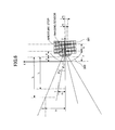
- FIG. 6 illustrates how to determine the positional relationship between the non-fisheye camera (i.e., the first camera 301 ) and the parabolic mirror 303 .
- the aperture stop of the non-fisheye camera (i.e., the aperture stop of the non-fisheye lens in the non-fisheye camera) is located at the focal point of the parabolic mirror 303 .
- s refers to the distance from the vertex of the parabolic mirror 303 to the central position of the front end of the non-fisheye camera, which is to be solved;
- f stands for the focal length of the parabolic mirror 303 , which is known;
- y 1 and y 2 respectively denote the heights of first and second objects 1 and 2 corresponding to two real objects, which may be determined by way of measurement, i.e., are known;
- x 1 and x 2 respectively mean the heights of the images generated based on the first and second objects, which are known (e.g., the height of each image may be acquired by determining the number of pixels of the same image along its height direction, and then, converting the number of the pixels into the height of the same image on the ground of a predetermined proportional
- x 1 , y 1 , x 2 , y 2 , l 1 , and l 2 are known, and p and k are unknown; as such, p and k may be solved.
- the half view angles corresponding to the objects points of the first and second objects 1 and 2 may be computed according to the following formulas (3) and (4).
- ⁇ 1 arc ⁇ ⁇ tan ⁇ ( y 1 p + l 1 ) ( 3 )
- ⁇ 2 arc ⁇ ⁇ tan ⁇ ( y 2 p + l 2 ) ( 4 )
- the key is solving the distance p between the aperture stop of the non-fisheye lens in the non-fisheye camera and the central point of the front end of the non-fisheye camera. Additionally, the measurement for determining p is carried out with respect to only the non-fisheye camera. In other words, when measuring x 1 , y 1 , x 2 , y 2 , l 1 , and l 2 , it is not necessary to dispose the parabolic mirror 303 .
- the parabolic mirror 303 may be set on the basis of the distance s. In this way, it is possible to ensure that the aperture stop of the non-fisheye camera and the focal point of the parabolic mirror 303 overlap, and the view angles of the non-fisheye camera (i.e., the first camera 301 ) and the second camera 302 are the same.
- the first camera 301 faces the second camera 302 , so, when taking a picture, the image of the second camera 302 may exist in the image photographed by the first camera 301 , and the image of the first camera 301 may also be present in the image photographed by the second camera 302 .
- the image of one of these two cameras is removed, which should not exist in the image taken by the other camera. For example, it is possible to delete this type of image by conducting post-processing. Alternatively, this kind of image may be eliminated by changing the hardware configuration of the camera device 300 .
- FIG. 7 illustrates a catadioptric camera formed by the second camera 302 and the parabolic mirror 303 , containing a light barrier 701 .
- the camera device 300 further includes a light barrier 701 which is provided on a central part of the front surface of the parabolic mirror 303 for shading a part of the curved surface of the parabolic mirror 303 from light, so that the light may not be reflected by or penetrate through the part of the curved surface of the parabolic mirror 303 to enter the first camera 301 and the second camera 302 .
- the light barrier 701 is a curved plate.
- the size of the light barrier 701 cannot be too small; otherwise, it is impossible to completely avoid a circumstance where the image of one of the first camera 301 and the second camera 302 exists in the image taken by the other camera. On the other hand, the size of the light barrier 701 cannot be too large; otherwise, the light is blocked too much so that the view field of each of the first camera 301 and the second camera 302 is reduced. As a result, it is necessary to properly design the size of the light barrier 701 .
- a two dimensional (X-Z) coordinate system is defined in which the origin is located at the vertex of the parabolic mirror 303 ;
- X axis is the common optical axis of the catadioptric camera and the first camera 301 ;
- X axis is perpendicular to Z axis; and
- (z 1 , x 1 ) refers to the coordinates of one end of the light barrier 701 .
- the surface equation of the parabolic mirror 303 may be expressed by the following formula (5).
- X 2 4fZ (5)
- the straight line passes through an edge point of the catadioptric camera (i.e., the second camera 302 ) and the focal point of the parabolic mirror 303 so as to define a boundary by which whether the non-fisheye camera can capture the second camera 302 may be distinguished.
- the straight line stands for a principal ray because it passes through the focal point of the parabolic mirror 303 .
- the intersection of the straight line and the parabolic mirror 303 is the one end of the light barrier 701 whose coordinates are (z 1 , x 1 ). Accordingly, the straight line may be expressed by the following formula (6).
- X ⁇ tan ⁇ Z+z tan ⁇ (6)
- ⁇ refers of a half view angle when the edge point of the second camera 302 serves as an object point, which may be calculated on the basis of the formulas (3) and (4) above, and z is equal to f.
- the light barrier 701 shown in FIG. 7 is just an example. It is clear to a person skilled in the art that the shape and location of the light barrier 701 may be changed as long as the light entering the area under the boundary (i.e., the straight line defined by the formula (6) above) may be shielded by the light barrier 701 .
- the light barrier 701 may not be a curved plate provided on the central part of the front surface of the parabolic mirror 303 as presented in FIG. 7 , but is a straight plate disposed between the intersection (z 1 , x 1 ) and its symmetric point with respect to Z axis.
- a method of shooting light having at least two wavelength,bands is given in this embodiment.
- FIG. 8 is a flowchart of the method according to this embodiment, which is applied to the camera device 300 according to the first embodiment.
- the method is inclusive of STEPS S 801 to S 802 .
- incident light enters the parabolic mirror 303 which is arranged between the first lens of the first camera 301 and the second lens of the second camera 302 as indicated in FIG. 3 .
- the first camera 301 containing the first lens receives the light having the first wavelength band.
- the second camera 302 including the second lens receives the light having the second wavelength band.
- the method further includes a step (not shown in the drawings) of providing the light barrier 701 on a central part of the front surface of the parabolic mirror 303 so as to shade a part of the curved surface of the parabolic mirror 303 from light, so that the light cannot be reflected by or penetrate through the part of the curved surface of the parabolic mirror 303 to enter the first camera 301 and the second camera 302 , as presented in FIG. 7 .
- the camera device 300 including the first camera 301 , the second camera 302 , the parabolic mirror 303 , and the light barrier 701 have been illustrated in the first embodiment, they are omitted here for the sake of convenience.
- the camera device 300 by letting the aperture stop of the first camera 301 coincide with the focal point of the parabolic mirror 303 , it is possible to achieve the same view field. Furthermore, since the parabolic mirror 303 is set between the first camera 301 and the second camera 302 whose lens are disposed facing each other, the miniaturization of the relating system may be realized. In addition, by further disposing the light barrier 701 on the parabolic mirror 303 , it possible to effectively avoid a case where the image of one of the first camera 301 and the second camera 302 exists in the image captured by the other camera.
Landscapes
- Health & Medical Sciences (AREA)
- Life Sciences & Earth Sciences (AREA)
- Engineering & Computer Science (AREA)
- Molecular Biology (AREA)
- Physics & Mathematics (AREA)
- Multimedia (AREA)
- Signal Processing (AREA)
- Medical Informatics (AREA)
- Nuclear Medicine, Radiotherapy & Molecular Imaging (AREA)
- Pathology (AREA)
- Animal Behavior & Ethology (AREA)
- Veterinary Medicine (AREA)
- Biophysics (AREA)
- Public Health (AREA)
- Biomedical Technology (AREA)
- Heart & Thoracic Surgery (AREA)
- General Health & Medical Sciences (AREA)
- Surgery (AREA)
- High Energy & Nuclear Physics (AREA)
- Radiology & Medical Imaging (AREA)
- General Physics & Mathematics (AREA)
- Spectroscopy & Molecular Physics (AREA)
- Computing Systems (AREA)
- Theoretical Computer Science (AREA)
- Computer Vision & Pattern Recognition (AREA)
- Optics & Photonics (AREA)
- Studio Devices (AREA)
Abstract
Description
s=f−p (2)
X2=4fZ (5)
X=−tanθZ+ztanθ (6)
Claims (10)
Applications Claiming Priority (3)
| Application Number | Priority Date | Filing Date | Title |
|---|---|---|---|
| CN201710123684.8A CN108540691B (en) | 2017-03-03 | 2017-03-03 | Camera device and method for photographing at least two wavelengths of light |
| CN201710123684.8 | 2017-03-03 | ||
| CN201710123684 | 2017-03-03 |
Publications (2)
| Publication Number | Publication Date |
|---|---|
| US20180249910A1 US20180249910A1 (en) | 2018-09-06 |
| US10478068B2 true US10478068B2 (en) | 2019-11-19 |
Family
ID=63357478
Family Applications (1)
| Application Number | Title | Priority Date | Filing Date |
|---|---|---|---|
| US15/869,710 Active 2038-07-14 US10478068B2 (en) | 2017-03-03 | 2018-01-12 | Camera device having a parabolic mirror set between dual cameras and method for shooting light having at least two wavelength bands |
Country Status (2)
| Country | Link |
|---|---|
| US (1) | US10478068B2 (en) |
| CN (1) | CN108540691B (en) |
Families Citing this family (5)
| Publication number | Priority date | Publication date | Assignee | Title |
|---|---|---|---|---|
| KR20190013224A (en) * | 2017-08-01 | 2019-02-11 | 엘지전자 주식회사 | Mobile terminal |
| US10560645B2 (en) * | 2017-09-22 | 2020-02-11 | Feedback, LLC | Immersive video environment using near-infrared video compositing |
| US10270986B2 (en) * | 2017-09-22 | 2019-04-23 | Feedback, LLC | Near-infrared video compositing |
| US10674096B2 (en) * | 2017-09-22 | 2020-06-02 | Feedback, LLC | Near-infrared video compositing |
| US12452502B2 (en) * | 2023-05-18 | 2025-10-21 | Bob Pilgrim | Dual-band panoramic camera system |
Citations (1)
| Publication number | Priority date | Publication date | Assignee | Title |
|---|---|---|---|---|
| US10335896B2 (en) * | 2016-07-15 | 2019-07-02 | Flir Systems, Inc. | Boresighting a laser to an imaging sensor systems and methods |
Family Cites Families (5)
| Publication number | Priority date | Publication date | Assignee | Title |
|---|---|---|---|---|
| JP4638374B2 (en) * | 2006-04-18 | 2011-02-23 | フェニックス電機株式会社 | Light source device |
| CN102116673A (en) * | 2011-01-27 | 2011-07-06 | 北京空间机电研究所 | Catadioptric hybrid multispectral imaging system |
| JP2014006108A (en) * | 2012-06-22 | 2014-01-16 | Azbil Corp | Optical particle detection device and method for detecting particle |
| CN203217159U (en) * | 2012-09-27 | 2013-09-25 | 中国科学院西安光学精密机械研究所 | Visible light, medium wave infrared and long wave infrared three-band optical imaging system |
| CN105444700B (en) * | 2015-12-25 | 2017-10-31 | 中国科学院光电研究院 | A kind of many parallelism of optical axis detection means of multi-wavelength and detection method |
-
2017
- 2017-03-03 CN CN201710123684.8A patent/CN108540691B/en active Active
-
2018
- 2018-01-12 US US15/869,710 patent/US10478068B2/en active Active
Patent Citations (1)
| Publication number | Priority date | Publication date | Assignee | Title |
|---|---|---|---|---|
| US10335896B2 (en) * | 2016-07-15 | 2019-07-02 | Flir Systems, Inc. | Boresighting a laser to an imaging sensor systems and methods |
Also Published As
| Publication number | Publication date |
|---|---|
| US20180249910A1 (en) | 2018-09-06 |
| CN108540691A (en) | 2018-09-14 |
| CN108540691B (en) | 2020-06-16 |
Similar Documents
| Publication | Publication Date | Title |
|---|---|---|
| US10478068B2 (en) | Camera device having a parabolic mirror set between dual cameras and method for shooting light having at least two wavelength bands | |
| US10310219B2 (en) | Imaging apparatus, imaging system that includes imaging apparatus, electron mirror system that includes imaging apparatus, and ranging apparatus that includes imaging apparatus | |
| CN103323113B (en) | Multispectral imager based on light fieldd imaging technique | |
| US20130188022A1 (en) | 3d zoom imager | |
| US20200210733A1 (en) | Enhanced video-based driver monitoring using phase detect sensors | |
| US11750907B2 (en) | Systems and methods for high-magnification high-resolution photography using a small imaging system | |
| CN107004685A (en) | Solid-state imaging device and electronic device | |
| JP2020057869A (en) | Imaging apparatus | |
| CN105282443A (en) | Method for imaging full-field-depth panoramic image | |
| CN211425662U (en) | Infrared long-wave multispectral imaging device based on microlens filter array | |
| US20200012119A1 (en) | Reducing glare for objects viewed through transparent surfaces | |
| CN107014490A (en) | A Real-Time Polarization Imaging System with Split-Focal Plane | |
| CN111551563B (en) | A multi-viewing angle detection device and detection system for display panel | |
| US7576925B2 (en) | System for increasing horizontal field of view of a camera | |
| KR101608316B1 (en) | An Acquisition apparatus and method of Iris image in outdoors and/or indoors | |
| CN115134480A (en) | Camera module, terminal equipment and imaging method | |
| JP2015232506A (en) | Array mirror system and infrared ray detection device | |
| Lavigne et al. | A new fusion algorithm for shadow penetration using visible and midwave infrared polarimetric images | |
| KR101469361B1 (en) | Apparatus for panorama image acquisition | |
| CN115032708A (en) | Method for improving object detectability by improving three-dimensional scale detection sensitivity | |
| CN207147631U (en) | Device for realizing scene imaging and target spectrum measurement | |
| JP5699557B2 (en) | Object identification device and object identification method | |
| TWI467236B (en) | Three-dimensional appearance remote measuring system and the method using the same | |
| KR101511226B1 (en) | Optical lens system and utilization using the same. | |
| CN101223538A (en) | 3D Image Detector |
Legal Events
| Date | Code | Title | Description |
|---|---|---|---|
| AS | Assignment |
Owner name: RICOH COMPANY, LTD., JAPAN Free format text: ASSIGNMENT OF ASSIGNORS INTEREST;ASSIGNORS:ZHANG, YUPENG;YI, HONG;GONG, WEITAO;AND OTHERS;REEL/FRAME:044609/0233 Effective date: 20171228 |
|
| FEPP | Fee payment procedure |
Free format text: ENTITY STATUS SET TO UNDISCOUNTED (ORIGINAL EVENT CODE: BIG.); ENTITY STATUS OF PATENT OWNER: LARGE ENTITY |
|
| STPP | Information on status: patent application and granting procedure in general |
Free format text: DOCKETED NEW CASE - READY FOR EXAMINATION |
|
| STPP | Information on status: patent application and granting procedure in general |
Free format text: NOTICE OF ALLOWANCE MAILED -- APPLICATION RECEIVED IN OFFICE OF PUBLICATIONS |
|
| STCF | Information on status: patent grant |
Free format text: PATENTED CASE |
|
| MAFP | Maintenance fee payment |
Free format text: PAYMENT OF MAINTENANCE FEE, 4TH YEAR, LARGE ENTITY (ORIGINAL EVENT CODE: M1551); ENTITY STATUS OF PATENT OWNER: LARGE ENTITY Year of fee payment: 4 |