US1047710A - Device for removing water from heated pistons. - Google Patents
Device for removing water from heated pistons. Download PDFInfo
- Publication number
- US1047710A US1047710A US68092212A US1912680922A US1047710A US 1047710 A US1047710 A US 1047710A US 68092212 A US68092212 A US 68092212A US 1912680922 A US1912680922 A US 1912680922A US 1047710 A US1047710 A US 1047710A
- Authority
- US
- United States
- Prior art keywords
- piston
- valve
- cylinder
- chamber
- steam
- Prior art date
- Legal status (The legal status is an assumption and is not a legal conclusion. Google has not performed a legal analysis and makes no representation as to the accuracy of the status listed.)
- Expired - Lifetime
Links
- XLYOFNOQVPJJNP-UHFFFAOYSA-N water Substances O XLYOFNOQVPJJNP-UHFFFAOYSA-N 0.000 title description 8
- 230000005494 condensation Effects 0.000 description 6
- 238000009833 condensation Methods 0.000 description 6
- 230000004048 modification Effects 0.000 description 3
- 238000012986 modification Methods 0.000 description 3
- 230000002093 peripheral effect Effects 0.000 description 3
Images
Classifications
-
- F—MECHANICAL ENGINEERING; LIGHTING; HEATING; WEAPONS; BLASTING
- F04—POSITIVE - DISPLACEMENT MACHINES FOR LIQUIDS; PUMPS FOR LIQUIDS OR ELASTIC FLUIDS
- F04B—POSITIVE-DISPLACEMENT MACHINES FOR LIQUIDS; PUMPS
- F04B53/00—Component parts, details or accessories not provided for in, or of interest apart from, groups F04B1/00 - F04B23/00 or F04B39/00 - F04B47/00
- F04B53/14—Pistons, piston-rods or piston-rod connections
Definitions
- My invention relates to devices for removing water from heated steam engine pistons.
- my invention relates to such devices as applied to hollow pistons provided with suitable openings.
- the object of my invention is to provide in a steam engine, a piston capable of being periodically. filled with charges of fresh steam as the engine is operated, thereby maintaining the body of' the piston at a high temperature and limiting condensation, and in further equipping this piston and its cooperating cylinder with means by which any water which does, nevertheless, condense within the piston, may be periodically and automatically discharged.
- my invention comprises a hollow piston,having a discharge valve arranged in its wall adapted to open into the v interiorbfthe piston, "said valve being provided with a space or Valve chamber whose outlet is in the periphery of the piston, and
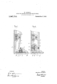
- Figure 1 represents a diametral section through one side of a piston embodying a preferred form of my invention, and through a portion of the cooperating cylinder wall and cylinder head, while Fig. 2 represents .a similar section showing a modified form of my invention.
- a s ring discharge vvalve a is inserted in the ollow .piston b at its lowest point.
- This valve opens into a central chamber 0 lying between the end wall or face 11 of the piston and the conical inner wall or face 6 and is provided with an outer space or valve chamber f lying between two piston rings g andg;
- a similar secondary valve it, also opening into the chamber 0,
- valve is now equalized, so as to'permit the water of condensation to pass through the valve and into the valve chamber f. Overflow of this water into the cylinder properwill be prevented by reason of the quickness with which the piston will be reversed so as to move toward the exhaust end.
- the pressure due to the charge of fresh steam, which is now being introduced becomes less in a manner determined by the character of the governingso that the initialpressure of the live steam contained-in chamber 0, will very quickly operate to close the valve h.
- this valve it will close when steam is cut off from the cylinder and expansion begins, because at that time the difference in pressure between the steam in the cylinder and the steam in chamber 0 will begin to increase very rapidly.
- the valve at will remain open during the intake and expansion'period since a charge of live steam will be carried along with the piston between the two rings 9 and 9' so as to act upon the lower side of this valve.
- the water of condensation in the chamber a is able to flow out into the valve chamber f.
- this valve will instantly close and the water of condensation in the valve chamber f, whichhas thus far been subjected to high pressure and is now suddenly exposed to atmospheric pressure will be violently spurted from the outlet opening.
- the piston reverses the above cycle of operations will be repeated.
- valve a is arranged in the lower portion of the end wall d of the piston. This location of the valve is more advantageous than the peripheral posit-ion of Fig. 1 in that the valve may be examined without entirely removing the piston from the cylinder.
- the chamber 0 does not discharge into a valve-chamber and then into the cylinder, but into the interior sub-chamber 1c and from thence through a passage Z which opens into the groove 9' between the two piston rings 9 and g.
- the valve a need not be provided with a spring.
- the operation of this form of my invention is substantially the same as that of the form shown in Fig. 1.
- My invention is applicable not only to engines employing horizontally operated pistons, but also for engines employing pistons operated vertically or at any desired angle with the horizontal.
- I claim 1 In a steam engine provided with a 1101- low piston having two piston rings and a cooperating cylinder, a spring discharge valve in the wall of said piston opening toward the interior thereof and having an outlet between the piston rings into thecylinder, and a secondary valve in the wall of said piston also opening toward the interior thereof and communicates with the inlet end of the cylinder, said cylinder being further provided with a groove which communicates both with the inlet end of the cylinder and with the aforesaid discharge valve outlet when the piston is at rest at the inlet end'of the cylinder.
- a spring discharge valve in the peripheral wall of said piston adapted to be opened toward the interior thereof, and a secondary valve in the end Wall of said piston also arranged to be opened toward the interior thereof and communicates with the inlet end of the cylinder, said piston being further provided with a peripheral valve chamber into which the discharge valve opens, and said cylinder being provided with a groove whichextends from the inlet end of the cylinder to the valve chamber when the piston is at rest at the inlet end of the cylinder.
- a steam engine provided with a hollow piston having two piston rings and a cooperating cylinder, a spring discharge valve inthe wall of said piston opening toward the interior thereof and having an outlet at thelowest point of said piston between the piston rings into the cylinder, and a secondary valve in the wall of said piston also opening toward the interior thereof and communicating with the inlet end of the cylinder, said cylinder being further provided with a groove which communicates both with the inlet end of the cylinder and with the aforesaid discharge valve outlet when the piston is at rest at the inlet end of the cylinder.
Landscapes
- Engineering & Computer Science (AREA)
- Mechanical Engineering (AREA)
- General Engineering & Computer Science (AREA)
- Lift Valve (AREA)
Description
W. SCHMIDT. DEVICE FOR REMOVING WATER FROM HEATED PISTONS.
- a APPLICATION FILED MAR. 1, 1912. 1,047,71 0.
TIIEF.
WITNESSES m MM "5" ATTORNEYS INVENTOR (VIA/$61M .SCl/M/DT Patented Dec. 17,1912;
' UNITED STATES PATENT, OFFICE.
\ WI'LHELM- SCHMIDT, or wILHELMsnonE, NEAR CASSEL, GERMANY, ASSIGNOR T0 SCHMIDTSCHE HEISSDAMPF GESELLSCHAFT B. H., or CARSEL, GERMANY, A
' CORPORATION OF GERMANY.
DEVICE FOR movme wa'r in 'rnom HEATED-PISTONS.
Specification of Letters Patent. Patented Dee, 17,1912. Application filed March ,1, 1912. serial N0. 680,922.
T 0 all whom it may concern: 7
Be it known that I, WILHELM SQHMIDT, a subject of the King of Prussia, Emperor of Germany, residing at Wilhelmshohe, near C ssel, Germany, have invented a new and useful Improvement in Devices for Removing Vater from Heated Pistons of Steam- Engines, of which the following is a specification.
My invention relates to devices for removing water from heated steam engine pistons.
More particularly my invention relates to such devices as applied to hollow pistons provided with suitable openings. p
The object of my invention is to provide in a steam engine, a piston capable of being periodically. filled with charges of fresh steam as the engine is operated, thereby maintaining the body of' the piston at a high temperature and limiting condensation, and in further equipping this piston and its cooperating cylinder with means by which any water which does, nevertheless, condense within the piston, may be periodically and automatically discharged.
More specifically my invention comprises a hollow piston,having a discharge valve arranged in its wall adapted to open into the v interiorbfthe piston, "said valve being provided with a space or Valve chamber whose outlet is in the periphery of the piston, and
a g'rdove so located in the cylinder wall that when the piston is at rest just before taking fresh steam, this outlet and the inlet end of theizylinder will be connected together.
My invention will be better understood by reference to the description following and to the drawings accompanying.
In the drawings, Figure 1 represents a diametral section through one side of a piston embodying a preferred form of my invention, and through a portion of the cooperating cylinder wall and cylinder head, while Fig. 2 represents .a similar section showing a modified form of my invention.
Referring to Fig. 1, a s ring discharge vvalve a is inserted in the ollow .piston b at its lowest point. This valve opens into a central chamber 0 lying between the end wall or face 11 of the piston and the conical inner wall or face 6 and is provided with an outer space or valve chamber f lying between two piston rings g andg; A similar secondary valve it, also opening into the chamber 0,
is provided in the end wall at of the piston and communicates withthe inlet end ofthe cylinder. Springs i and z" tend respectively to keep the two valves normally open, the
spring 2' being more powerful than the I spring 2''. At the left hand or inlet end of the cylinder is a short groove jextending from the 'end to about the center of the valve chamber 7 when the piston is at its pointof rest.
The operation of my invention is as follows: As the piston moves from the right hand or exhaust end" of the cylinder toward the intake, both valves a and it will be closed owing to the pressure of the steam contained in the chamber 0 (as will be described) being higherthan the pressure in the inlet end of the cylinder from which steam has just been exhausted and is now cut off. Owing to condensation the pressure in the chamber a will be somewhat less than that of live steam and the water of this condensation will collect at the bottom of the chamber over the valve'a. As the piston moves tothe valve chamber f will reach and open into the groove 7' whereby live steam will belead under the valve a, which valve will at once be raised by its spring 71, since the pressure on each side of the. valve is now equalized, so as to'permit the water of condensation to pass through the valve and into the valve chamber f. Overflow of this water into the cylinder properwill be prevented by reason of the quickness with which the piston will be reversed so as to move toward the exhaust end. As the piston moves toward the exhaust end of the cylinder the pressure due to the charge of fresh steam, which is now being introduced, becomes less in a manner determined by the character of the governingso that the initialpressure of the live steam contained-in chamber 0, will very quickly operate to close the valve h. At the latest this valve it will close when steam is cut off from the cylinder and expansion begins, because at that time the difference in pressure between the steam in the cylinder and the steam in chamber 0 will begin to increase very rapidly. The valve at will remain open during the intake and expansion'period since a charge of live steam will be carried along with the piston between the two rings 9 and 9' so as to act upon the lower side of this valve. During all this time, while the piston is moving toward the exhaust end of the cylinder, the water of condensation in the chamber a is able to flow out into the valve chamber f. As soon as the piston has carried the valve a past the outlet opening this valve will instantly close and the water of condensation in the valve chamber f, whichhas thus far been subjected to high pressure and is now suddenly exposed to atmospheric pressure will be violently spurted from the outlet opening. As the piston reverses, the above cycle of operations will be repeated.
In the modification of Fig. 2 the valve a is arranged in the lower portion of the end wall d of the piston. This location of the valve is more advantageous than the peripheral posit-ion of Fig. 1 in that the valve may be examined without entirely removing the piston from the cylinder. In this modification the chamber 0 does not discharge into a valve-chamber and then into the cylinder, but into the interior sub-chamber 1c and from thence through a passage Z which opens into the groove 9' between the two piston rings 9 and g. In this modification the valve a need not be provided with a spring. The operation of this form of my invention is substantially the same as that of the form shown in Fig. 1.
Instead of a single valve a I may, if I prefer, employ a plurality of valves without departing from the spirit of my invention.
My invention is applicable not only to engines employing horizontally operated pistons, but also for engines employing pistons operated vertically or at any desired angle with the horizontal.
Having described my invention, I claim 1. In a steam engine provided with a 1101- low piston having two piston rings and a cooperating cylinder, a spring discharge valve in the wall of said piston opening toward the interior thereof and having an outlet between the piston rings into thecylinder, and a secondary valve in the wall of said piston also opening toward the interior thereof and communicates with the inlet end of the cylinder, said cylinder being further provided with a groove which communicates both with the inlet end of the cylinder and with the aforesaid discharge valve outlet when the piston is at rest at the inlet end'of the cylinder.
2. In a steam engine provided with a hollow piston having two piston rings and a cooperating cylinder, a spring discharge valve in the peripheral wall of said piston adapted to be opened toward the interior thereof, and a secondary valve in the end Wall of said piston also arranged to be opened toward the interior thereof and communicates with the inlet end of the cylinder, said piston being further provided with a peripheral valve chamber into which the discharge valve opens, and said cylinder being provided with a groove whichextends from the inlet end of the cylinder to the valve chamber when the piston is at rest at the inlet end of the cylinder.
3. In a. steam engine provided with a hollow piston having two piston rings and a cooperating cylinder, a spring discharge valve inthe wall of said piston opening toward the interior thereof and having an outlet at thelowest point of said piston between the piston rings into the cylinder, and a secondary valve in the wall of said piston also opening toward the interior thereof and communicating with the inlet end of the cylinder, said cylinder being further provided with a groove which communicates both with the inlet end of the cylinder and with the aforesaid discharge valve outlet when the piston is at rest at the inlet end of the cylinder.
In'testimony whereof, I have hereunto set my hand in the presence of two subscribing witnesses.
WILHELM SCHMIDT.
Witnesses EGMONT DOETILOFF, JULIUS FRANKIE.
Priority Applications (1)
| Application Number | Priority Date | Filing Date | Title |
|---|---|---|---|
| US68092212A US1047710A (en) | 1912-03-01 | 1912-03-01 | Device for removing water from heated pistons. |
Applications Claiming Priority (1)
| Application Number | Priority Date | Filing Date | Title |
|---|---|---|---|
| US68092212A US1047710A (en) | 1912-03-01 | 1912-03-01 | Device for removing water from heated pistons. |
Publications (1)
| Publication Number | Publication Date |
|---|---|
| US1047710A true US1047710A (en) | 1912-12-17 |
Family
ID=3115981
Family Applications (1)
| Application Number | Title | Priority Date | Filing Date |
|---|---|---|---|
| US68092212A Expired - Lifetime US1047710A (en) | 1912-03-01 | 1912-03-01 | Device for removing water from heated pistons. |
Country Status (1)
| Country | Link |
|---|---|
| US (1) | US1047710A (en) |
-
1912
- 1912-03-01 US US68092212A patent/US1047710A/en not_active Expired - Lifetime
Similar Documents
| Publication | Publication Date | Title |
|---|---|---|
| US1036288A (en) | Gaseous-power generator. | |
| US2431859A (en) | Two-cycle engine, crankcase compression, valve piston | |
| US789687A (en) | Automatic blower for guns. | |
| US1286142A (en) | Rotating-cylinder internal-combustion engine. | |
| US332312A (en) | wilcox | |
| US2074487A (en) | Valve and valve gear for internal combustion engines | |
| US3081756A (en) | Free piston engine | |
| US2458198A (en) | Control for spill ports for freepiston units | |
| US1386567A (en) | Air-pump | |
| US1652487A (en) | Bbtyb | |
| US1069794A (en) | Internal-combustion engine. | |
| US1254976A (en) | Engine-valve. | |
| US2337668A (en) | Two-cycle engine | |
| US1018300A (en) | Condensing steam-engine. | |
| US2344802A (en) | Steam engine valve mechanism | |
| US1700700A (en) | Nozzle valve for internal-combustion turbines | |
| US1235145A (en) | Internal-combustion motor. | |
| US1251043A (en) | Method and apparatus for burning fuel. | |
| US1146990A (en) | Four-cycle gasolene-engine. | |
| US2063666A (en) | Two-cycle engine | |
| USRE12024E (en) | Gas and steam convertible engine | |
| US2458147A (en) | Control for free-piston units | |
| US1443694A (en) | Device for operating hinged or similar members | |
| US2441272A (en) | Spill port control for free-piston units | |
| US959812A (en) | Rotary engine. |