US10469800B2 - Always-on telepresence device - Google Patents
Always-on telepresence device Download PDFInfo
- Publication number
- US10469800B2 US10469800B2 US15/784,859 US201715784859A US10469800B2 US 10469800 B2 US10469800 B2 US 10469800B2 US 201715784859 A US201715784859 A US 201715784859A US 10469800 B2 US10469800 B2 US 10469800B2
- Authority
- US
- United States
- Prior art keywords
- computing device
- audio
- video
- video display
- capture
- Prior art date
- Legal status (The legal status is an assumption and is not a legal conclusion. Google has not performed a legal analysis and makes no representation as to the accuracy of the status listed.)
- Expired - Fee Related
Links
- 238000004891 communication Methods 0.000 claims description 41
- 238000000034 method Methods 0.000 claims description 6
- 230000005236 sound signal Effects 0.000 claims 1
- 230000002269 spontaneous effect Effects 0.000 description 3
- 238000013459 approach Methods 0.000 description 2
- 238000005516 engineering process Methods 0.000 description 2
- 230000000474 nursing effect Effects 0.000 description 2
- 238000010586 diagram Methods 0.000 description 1
- 230000001815 facial effect Effects 0.000 description 1
- 230000006870 function Effects 0.000 description 1
- 230000007774 longterm Effects 0.000 description 1
- 230000001105 regulatory effect Effects 0.000 description 1
- 238000004088 simulation Methods 0.000 description 1
- 230000000007 visual effect Effects 0.000 description 1
Images


Classifications
-
- H—ELECTRICITY
- H04—ELECTRIC COMMUNICATION TECHNIQUE
- H04N—PICTORIAL COMMUNICATION, e.g. TELEVISION
- H04N7/00—Television systems
- H04N7/14—Systems for two-way working
- H04N7/141—Systems for two-way working between two video terminals, e.g. videophone
- H04N7/147—Communication arrangements, e.g. identifying the communication as a video-communication, intermediate storage of the signals
-
- G—PHYSICS
- G06—COMPUTING; CALCULATING OR COUNTING
- G06K—GRAPHICAL DATA READING; PRESENTATION OF DATA; RECORD CARRIERS; HANDLING RECORD CARRIERS
- G06K7/00—Methods or arrangements for sensing record carriers, e.g. for reading patterns
- G06K7/10—Methods or arrangements for sensing record carriers, e.g. for reading patterns by electromagnetic radiation, e.g. optical sensing; by corpuscular radiation
- G06K7/14—Methods or arrangements for sensing record carriers, e.g. for reading patterns by electromagnetic radiation, e.g. optical sensing; by corpuscular radiation using light without selection of wavelength, e.g. sensing reflected white light
- G06K7/1404—Methods for optical code recognition
- G06K7/1408—Methods for optical code recognition the method being specifically adapted for the type of code
- G06K7/1417—2D bar codes
-
- G10L15/265—
-
- G—PHYSICS
- G10—MUSICAL INSTRUMENTS; ACOUSTICS
- G10L—SPEECH ANALYSIS OR SYNTHESIS; SPEECH RECOGNITION; SPEECH OR VOICE PROCESSING; SPEECH OR AUDIO CODING OR DECODING
- G10L21/00—Processing of the speech or voice signal to produce another audible or non-audible signal, e.g. visual or tactile, in order to modify its quality or its intelligibility
- G10L21/02—Speech enhancement, e.g. noise reduction or echo cancellation
- G10L21/0208—Noise filtering
- G10L21/0216—Noise filtering characterised by the method used for estimating noise
- G10L21/0232—Processing in the frequency domain
-
- G—PHYSICS
- G10—MUSICAL INSTRUMENTS; ACOUSTICS
- G10L—SPEECH ANALYSIS OR SYNTHESIS; SPEECH RECOGNITION; SPEECH OR VOICE PROCESSING; SPEECH OR AUDIO CODING OR DECODING
- G10L25/00—Speech or voice analysis techniques not restricted to a single one of groups G10L15/00 - G10L21/00
- G10L25/48—Speech or voice analysis techniques not restricted to a single one of groups G10L15/00 - G10L21/00 specially adapted for particular use
- G10L25/51—Speech or voice analysis techniques not restricted to a single one of groups G10L15/00 - G10L21/00 specially adapted for particular use for comparison or discrimination
-
- G—PHYSICS
- G10—MUSICAL INSTRUMENTS; ACOUSTICS
- G10L—SPEECH ANALYSIS OR SYNTHESIS; SPEECH RECOGNITION; SPEECH OR VOICE PROCESSING; SPEECH OR AUDIO CODING OR DECODING
- G10L25/00—Speech or voice analysis techniques not restricted to a single one of groups G10L15/00 - G10L21/00
- G10L25/78—Detection of presence or absence of voice signals
-
- H—ELECTRICITY
- H04—ELECTRIC COMMUNICATION TECHNIQUE
- H04L—TRANSMISSION OF DIGITAL INFORMATION, e.g. TELEGRAPHIC COMMUNICATION
- H04L65/00—Network arrangements, protocols or services for supporting real-time applications in data packet communication
- H04L65/1066—Session management
- H04L65/1069—Session establishment or de-establishment
-
- H—ELECTRICITY
- H04—ELECTRIC COMMUNICATION TECHNIQUE
- H04L—TRANSMISSION OF DIGITAL INFORMATION, e.g. TELEGRAPHIC COMMUNICATION
- H04L65/00—Network arrangements, protocols or services for supporting real-time applications in data packet communication
- H04L65/40—Support for services or applications
- H04L65/403—Arrangements for multi-party communication, e.g. for conferences
-
- H—ELECTRICITY
- H04—ELECTRIC COMMUNICATION TECHNIQUE
- H04L—TRANSMISSION OF DIGITAL INFORMATION, e.g. TELEGRAPHIC COMMUNICATION
- H04L67/00—Network arrangements or protocols for supporting network services or applications
- H04L67/01—Protocols
- H04L67/12—Protocols specially adapted for proprietary or special-purpose networking environments, e.g. medical networks, sensor networks, networks in vehicles or remote metering networks
-
- H—ELECTRICITY
- H04—ELECTRIC COMMUNICATION TECHNIQUE
- H04N—PICTORIAL COMMUNICATION, e.g. TELEVISION
- H04N5/00—Details of television systems
- H04N5/222—Studio circuitry; Studio devices; Studio equipment
- H04N5/262—Studio circuits, e.g. for mixing, switching-over, change of character of image, other special effects ; Cameras specially adapted for the electronic generation of special effects
- H04N5/2628—Alteration of picture size, shape, position or orientation, e.g. zooming, rotation, rolling, perspective, translation
-
- H—ELECTRICITY
- H04—ELECTRIC COMMUNICATION TECHNIQUE
- H04N—PICTORIAL COMMUNICATION, e.g. TELEVISION
- H04N5/00—Details of television systems
- H04N5/44—Receiver circuitry for the reception of television signals according to analogue transmission standards
- H04N5/445—Receiver circuitry for the reception of television signals according to analogue transmission standards for displaying additional information
-
- H—ELECTRICITY
- H04—ELECTRIC COMMUNICATION TECHNIQUE
- H04N—PICTORIAL COMMUNICATION, e.g. TELEVISION
- H04N7/00—Television systems
- H04N7/14—Systems for two-way working
- H04N7/141—Systems for two-way working between two video terminals, e.g. videophone
- H04N7/142—Constructional details of the terminal equipment, e.g. arrangements of the camera and the display
-
- G06K9/00228—
-
- G—PHYSICS
- G06—COMPUTING; CALCULATING OR COUNTING
- G06T—IMAGE DATA PROCESSING OR GENERATION, IN GENERAL
- G06T7/00—Image analysis
- G06T7/70—Determining position or orientation of objects or cameras
-
- G—PHYSICS
- G06—COMPUTING; CALCULATING OR COUNTING
- G06V—IMAGE OR VIDEO RECOGNITION OR UNDERSTANDING
- G06V40/00—Recognition of biometric, human-related or animal-related patterns in image or video data
- G06V40/10—Human or animal bodies, e.g. vehicle occupants or pedestrians; Body parts, e.g. hands
- G06V40/16—Human faces, e.g. facial parts, sketches or expressions
- G06V40/161—Detection; Localisation; Normalisation
-
- G—PHYSICS
- G10—MUSICAL INSTRUMENTS; ACOUSTICS
- G10L—SPEECH ANALYSIS OR SYNTHESIS; SPEECH RECOGNITION; SPEECH OR VOICE PROCESSING; SPEECH OR AUDIO CODING OR DECODING
- G10L15/00—Speech recognition
- G10L15/26—Speech to text systems
-
- G—PHYSICS
- G10—MUSICAL INSTRUMENTS; ACOUSTICS
- G10L—SPEECH ANALYSIS OR SYNTHESIS; SPEECH RECOGNITION; SPEECH OR VOICE PROCESSING; SPEECH OR AUDIO CODING OR DECODING
- G10L21/00—Processing of the speech or voice signal to produce another audible or non-audible signal, e.g. visual or tactile, in order to modify its quality or its intelligibility
- G10L21/02—Speech enhancement, e.g. noise reduction or echo cancellation
- G10L21/0208—Noise filtering
- G10L2021/02082—Noise filtering the noise being echo, reverberation of the speech
-
- G—PHYSICS
- G10—MUSICAL INSTRUMENTS; ACOUSTICS
- G10L—SPEECH ANALYSIS OR SYNTHESIS; SPEECH RECOGNITION; SPEECH OR VOICE PROCESSING; SPEECH OR AUDIO CODING OR DECODING
- G10L25/00—Speech or voice analysis techniques not restricted to a single one of groups G10L15/00 - G10L21/00
- G10L25/48—Speech or voice analysis techniques not restricted to a single one of groups G10L15/00 - G10L21/00 specially adapted for particular use
-
- H—ELECTRICITY
- H04—ELECTRIC COMMUNICATION TECHNIQUE
- H04L—TRANSMISSION OF DIGITAL INFORMATION, e.g. TELEGRAPHIC COMMUNICATION
- H04L67/00—Network arrangements or protocols for supporting network services or applications
- H04L67/01—Protocols
- H04L67/10—Protocols in which an application is distributed across nodes in the network
- H04L67/104—Peer-to-peer [P2P] networks
-
- H—ELECTRICITY
- H04—ELECTRIC COMMUNICATION TECHNIQUE
- H04N—PICTORIAL COMMUNICATION, e.g. TELEVISION
- H04N7/00—Television systems
- H04N7/14—Systems for two-way working
- H04N7/141—Systems for two-way working between two video terminals, e.g. videophone
- H04N7/142—Constructional details of the terminal equipment, e.g. arrangements of the camera and the display
- H04N2007/145—Handheld terminals
-
- H—ELECTRICITY
- H04—ELECTRIC COMMUNICATION TECHNIQUE
- H04N—PICTORIAL COMMUNICATION, e.g. TELEVISION
- H04N23/00—Cameras or camera modules comprising electronic image sensors; Control thereof
- H04N23/60—Control of cameras or camera modules
- H04N23/698—Control of cameras or camera modules for achieving an enlarged field of view, e.g. panoramic image capture
-
- H—ELECTRICITY
- H04—ELECTRIC COMMUNICATION TECHNIQUE
- H04N—PICTORIAL COMMUNICATION, e.g. TELEVISION
- H04N23/00—Cameras or camera modules comprising electronic image sensors; Control thereof
- H04N23/90—Arrangement of cameras or camera modules, e.g. multiple cameras in TV studios or sports stadiums
-
- H04N5/23238—
-
- H04N5/247—
-
- H—ELECTRICITY
- H04—ELECTRIC COMMUNICATION TECHNIQUE
- H04N—PICTORIAL COMMUNICATION, e.g. TELEVISION
- H04N5/00—Details of television systems
- H04N5/44—Receiver circuitry for the reception of television signals according to analogue transmission standards
- H04N5/57—Control of contrast or brightness
- H04N5/58—Control of contrast or brightness in dependence upon ambient light
-
- H—ELECTRICITY
- H04—ELECTRIC COMMUNICATION TECHNIQUE
- H04N—PICTORIAL COMMUNICATION, e.g. TELEVISION
- H04N5/00—Details of television systems
- H04N5/44—Receiver circuitry for the reception of television signals according to analogue transmission standards
- H04N5/60—Receiver circuitry for the reception of television signals according to analogue transmission standards for the sound signals
Definitions
- a peer-to-peer connection between A, B, and C would mean that the system runs three connections—AB, BC, and AC. This means that for each participant, there are two outgoing video connections, which takes up a lot of bandwidth. Obviously, the more participants there are, the more connections there are and the more bandwidth is used; the peer-to-peer approach does not scale very well.
- An alternative to that is group chat, which connects A, B, and C to a cloud server, which then delivers the video/audio stream to every participant. While this scales better, this means that a cloud service will then have to be maintained, which is expensive. Furthermore, the bandwidth of each connection will need to be regulated.
- An object of the present invention is to provide a communication system that is simple to connect, does not require any attention or setup after it's initially connected, and stays always-on.
- Another object of the present invention is to provide a communication device that provides an opportunity for “incidental contact”.
- the system of the present invention comprises two communication devices, each one comprising a video display, an audio emission system, an audio capture device, a video capture device, and a computing device connected to all the other components.
- Each computing device comprises a unique identification code, and they are configured to only connect to each other and to no other device.
- the connection between the two devices is an always-on connection.
- connection between the two devices if the connection between the two devices is accidentally interrupted, it is automatically reestablished.
- the two communication devices are preferably configured to connect to each other by the following steps.
- a QR code comprising the other device's unique ID is presented to the video capture device.
- the video capture device is used to transmit the QR code to the computing device, which reads the other device's unique ID from the QR code and configures the computing device to only connect to a device bearing that unique ID.
- the QR code may be presented to the video capture device on a smartphone screen or on a sheet of paper.
- the QR code comprises the address of a server; when it is displayed for the video capture device, the computing device connects to the server and the server provides the other device's unique ID for the computing device and configures the computing device to only connect to a device bearing that unique ID.
- At least one of the video capture devices is a wide-angle camera.
- At least one of the audio capture devices is a far-field echo canceling microphone.
- At least one computing device is configured to determine if a person's face is present in the video data and zoom in on the person's face.
- At least one computing device is configured to determine if a particular person is present; the other computing device then notifies a user when that particular person is present.
- At least one of the video displays life size images.
- At least one of the communication devices provides closed captioning.
- At least one video display is a television and the computing device comprises a bracket for mounting the computing device on the television.
- the video displayed on the video display changes depending on the head position of a user located in front of the video display.
- audio is muted when no human voices are present in the audio data.
- the audio data comprises a call for help.
- the system automatically adjusts the brightness of the video display and the volume of the audio so that it matches the real-world levels detected by the video and audio capture device on the other communication device.
- the first computing device connects to the second computing device by a peer-to-peer network connection. If a peer-to-peer network connection is permanently or temporarily unavailable, the first computing device connects to the second computing device via a central server.
- FIG. 1 shows a block diagram of a communication device of the present invention.
- FIG. 2 shows the preferred embodiment of the present invention in use.
- FIG. 3 shows a close-up view of the preferred embodiment of the present invention in use.
- FIG. 4 shows an embodiment of the provisioning method of the present invention.
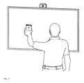
- FIG. 5 shows a user performing an embodiment of the provisioning method of the present invention.
- FIG. 6 shows an embodiment of the housing of the present invention.
- the system of the present invention comprises two identical communication devices connected to each other by a network.
- Each communication device comprises a display screen 100 , an audio speaker 110 , a microphone array 120 , a camera 130 , a communication module 140 , and a processor and memory 150 .
- the display screen 100 is preferably a television, and the audio speaker 110 is preferably the speaker of the television; however, any display screen, such as a computer monitor or a projector, may be used with the present invention; similarly, any speaker maybe used with the present invention.
- the display screen 100 is preferably large enough so that the images on the screen are life-size. While this is not required to practice the present invention, having life-size images on the screen adds to the feeling of having a “portal” into another room and adds to the realism of the experience.
- the camera 130 used with the preferred embodiment of the present invention is preferably a wide-angle camera that can capture a view of an entire room.
- Prior art videoconferencing systems tend to use narrow-angle cameras that work only if a person is sitting in front of the computer; since the present invention is built for “incidental contact”, when a user may be wandering in and out of a room, it needs to capture a wider view.
- the microphone 120 used with the preferred embodiment of the present invention is preferably a far-field echo canceling microphone array; an embodiment of such an array is shown in FIG. 2 .
- Such a microphone array is good at picking up sound from a distance, which is needed if a user is wandering in and out of the room or walking around the room as they talk
- the communication module 140 is preferably able to connect to the Internet by a wi-fi connection or an Ethernet cable. As discussed above, the communication module 140 only connects to one other device over a network.
- the communication module 140 is preferably provisioned prior to first use with the unique identification code of the other device. This enables any further use of the communication device to be effortless; the connection is simply always on, and the communication device requires no attention or setup from the user once it is initially provisioned. If the connection is interrupted, the communication module attempts to reconnect automatically to the other device; no attention or action by the user is required.
- the communication module preferably connects to the other device by a peer-to-peer network connection; however, if peer-to-peer is blocked by a network issue or by some other problem, the communication module can connect to a central server to maintain the connection to the other device.
- the communication module preferably selects the best method of connection—peer-to-peer or central server—depending on the situation (i.e. available bandwidth and available connections).
- the processor and memory 150 preferably comprise enough computing power and memory to control the camera, microphone, display screen, and speaker.
- the processor and memory comprise programming that enables it to receive data from the camera and microphone and transmit it over a network to another communication device, as well as programming that enables it to perform certain other functions that may be needed in some embodiments of the present invention, which will be discussed hereinbelow.
- FIG. 2 shows a view of the present invention in use in an office environment.
- the present invention provides a simple “portal” into another room. This enables “incidental contact” between two geographically distinct spaces that feels as immediate as looking through an open door into another room.
- both communication devices are connected to the cloud 500 .
- FIG. 3 shows a close-up view of the present invention in use.
- the display is preferably large enough to allow life-size images and located in such a way that it could be perceived as a “window” or “portal”. Since it is always-on, it becomes an expected feature of the office and the people one sees on the screen are perceived as part of one's normal social environment.
- the present invention may be used to unite two offices of the same company; an employee at one office can simply “run into” another employee at a different office at the watercooler and have a chat, thus exchanging ideas and establishing a stronger personal connection with the other employee. It may be used to unite families; a grandparent living far away may simply see and hear their grandchild at any time and enjoy frequent incidental contact. It may be used to help patients in long-term care feel connected to the world; a communication device such as this may be placed in a nursing home room so that the patient has an always-on and realistic view of their family or friends. Other applications of the invention may doubtless become apparent as time goes on.
- FIG. 4 shows a method of provisioning the communication device of the present invention.
- the provisioning step is performed only once; after the communication device is paired with another communication device, it stays connected to the other communication device until the connection is interrupted, in which case it will attempt to reconnect automatically.
- the provisioning step needs to be simple and foolproof, since some of the potential users are the elderly, hospital patients in nursing homes, and other people who are not very tech-savvy.
- the first step is checking whether or not the communication device is connected to the Internet. If it is not connected to the Internet, the connection is first set up. This may be done by means of a phone app or an Ethernet cable.
- the phone app preferably connects to the communication device and provides an interface by which a user can enter a wi-fi network and password so that the communication device can connect to the Internet.
- the communication device After the communication device is connected to the Internet, it gets the “room” information—i.e. the address of another communication device to which it needs to connect. If the room is present, it connects to the room and presents the room video to the user. If the room is not present, it prompts the user to present a QR code (either printed out on paper or displayed on the screen of a smartphone) to the camera.
- FIG. 5 shows a user displaying a QR code to the camera on the screen of a smartphone. Once it detects a QR code, it scans it and sends the information to a server, which reads it, determines the address of the room, and connects the device to the room.
- the video of the room (together with audio) is then presented until the connection is interrupted, in which case the system goes through the same steps of establishing the Internet connection and re-finding the room. Also, if a QR code is ever displayed in the system's field of vision, it scans it, sends the information to a server, and then connects to a different room if the QR code encodes a different room.
- the provisioning step may be performed by calling a phone number instead of a displaying a QR code.
- a user would call a phone number while standing in front of the communication device.
- the phone would then play a particular sound which would be picked up by the microphone of the present invention; the sound would then be sent to a server for decoding and the address of the room will be identified.
- the device will then be connected to the room.
- FIG. 6 shows the back view of the preferred embodiment of the system of the present invention.
- the display is a large-screen television 600 , which also provides the speakers (not shown in the Figure).
- the camera and microphone module 610 is located at the top of the television to provide optimal viewing.
- the processor and memory are located in housing 620 , which is attached to the back of the television 600 and connected to it via an HDMI cable 630 .
- An Ethernet cable 640 , an HDMI cable 650 , and a power cord 660 extend from the housing 620 .
- the present invention detects the head position of a user positioned in front of the device and adjusts the view based on any changes in the user's head position. This is intended to create greater realism in showing the display as a “portal” into another room.
- the adjustment to the view is preferably the same as a user would see if they were looking through a window into a real room and changing their head position.
- the system may turn off this feature if more than one user is present in front of the device, or adjust the view depending on the head position of one of the users (for example, the user who is closest to the device or the user who is talking).
- the present invention automatically adjusts the volume, brightness, and color of the display to match what it is in the real scene received by the other communication device. This adds to the realism of the scene.
- the system preferably measures the signal-to-noise ratio of the sound generated by the speakers and compares it to the signal-to-noise ratio of the sound received by the microphones and adjusts the speakers until the two are identical.
- the system preferably measures the brightness and tone values of the visual information received by the camera and adjusts the brightness and tone values of the screen until the two are identical.
- the present invention comprises a “privacy curtain” that may be used to turn off the camera or microphone when the user wishes for privacy.
- the “privacy curtain” may be an actual curtain drawn across the screen, to add to the realism of the device (in which case, the curtain preferably comprises a proximity switch that turns off the camera and microphone), or a simple switch.
- the camera and microphone may be turned off with a hand gesture.
- the present invention is configured to identify any faces present in the video stream and to zoom in on a face. If only one person's face is present in the room, the system zooms in on that face. If more than one face is present in the room, the system may zoom in on the face of the person who is talking, or may zoom in on both faces. In an embodiment, the system may display the zoomed-in face in a separate area of the screen while maintaining a view of the entire room on the screen.
- the present invention is configured to perform facial recognition and identifies the users present in the room. This enables the system to send a notification if a particular user enters the room or to mute the sound and/or turn off the display when no one is present.
- the notification may be delivered to a user's smartphone or played as a sound.
- the present invention is configured to identify hand gestures made by a user. This enables the user to interact with the system. For example, the system may identify a particular gesture as a “panic button”, and send an emergency signal if the user makes that gesture.
- the system detects any human voices present in the sound received by the microphones. If human voices are present, the system generates closed captioning of their speech and sends it to the other device to be displayed on the screen.
- the video/audio stream may be recorded.
Abstract
Description
Claims (15)
Priority Applications (1)
| Application Number | Priority Date | Filing Date | Title |
|---|---|---|---|
| US15/784,859 US10469800B2 (en) | 2017-01-26 | 2017-10-16 | Always-on telepresence device |
Applications Claiming Priority (2)
| Application Number | Priority Date | Filing Date | Title |
|---|---|---|---|
| US201762451015P | 2017-01-26 | 2017-01-26 | |
| US15/784,859 US10469800B2 (en) | 2017-01-26 | 2017-10-16 | Always-on telepresence device |
Publications (2)
| Publication Number | Publication Date |
|---|---|
| US20180309957A1 US20180309957A1 (en) | 2018-10-25 |
| US10469800B2 true US10469800B2 (en) | 2019-11-05 |
Family
ID=63854827
Family Applications (1)
| Application Number | Title | Priority Date | Filing Date |
|---|---|---|---|
| US15/784,859 Expired - Fee Related US10469800B2 (en) | 2017-01-26 | 2017-10-16 | Always-on telepresence device |
Country Status (1)
| Country | Link |
|---|---|
| US (1) | US10469800B2 (en) |
Families Citing this family (3)
| Publication number | Priority date | Publication date | Assignee | Title |
|---|---|---|---|---|
| EP3602272B1 (en) | 2017-11-06 | 2023-11-22 | Google LLC | Methods and systems for attending to a presenting user |
| US10619787B1 (en) * | 2018-08-29 | 2020-04-14 | Facebook, Inc. | Mounting systems for a video-conferencing device, video conferencing systems, and related methods |
| SE2051155A1 (en) * | 2020-10-02 | 2021-10-05 | Ikea Supply Ag | A panel-shaped electronic device with intersecting cable channels on the back-side |
Citations (14)
| Publication number | Priority date | Publication date | Assignee | Title |
|---|---|---|---|---|
| US20100039498A1 (en) * | 2007-05-17 | 2010-02-18 | Huawei Technologies Co., Ltd. | Caption display method, video communication system and device |
| US20100066804A1 (en) * | 2008-09-16 | 2010-03-18 | Wham! Inc. | Real time video communications system |
| US20100332579A1 (en) * | 2009-06-24 | 2010-12-30 | Microsoft Corporation | Proximity guided data discovery |
| US20110134237A1 (en) * | 2008-08-04 | 2011-06-09 | Koninklijke Philips Electronics N.V. | Communication device with peripheral viewing means |
| US20130329000A1 (en) * | 2012-06-11 | 2013-12-12 | Gamil A. Cain | Providing spontaneous connection and interaction between local and remote interaction devices |
| US8744054B2 (en) * | 2006-06-29 | 2014-06-03 | Apple Inc. | Method and system for automatic call redialing |
| US20140268511A1 (en) * | 2013-03-14 | 2014-09-18 | Related Visual Services, Inc. | Control box mounting bracket |
| US20160379660A1 (en) * | 2015-06-24 | 2016-12-29 | Shawn Crispin Wright | Filtering sounds for conferencing applications |
| US20170034362A1 (en) * | 2014-04-16 | 2017-02-02 | Huawei Technologies Co., Ltd. | Method and Apparatus for Adjusting Volume of User Terminal, and Terminal |
| US20170048488A1 (en) * | 2015-08-14 | 2017-02-16 | Microsoft Technology Licensing, Llc | Dynamic communication portal between locations |
| US9848166B2 (en) * | 2014-03-28 | 2017-12-19 | Daiwa House Industry Co., Ltd. | Communication unit |
| US20180131899A1 (en) * | 2014-07-15 | 2018-05-10 | Ainemo Inc. | Communication terminal and tool installed on mobile terminal |
| US20180136824A1 (en) * | 2016-11-16 | 2018-05-17 | Dell Products L.P. | System and method for provisioning a user interface for sharing |
| US20190007648A1 (en) * | 2015-01-21 | 2019-01-03 | Alejo SERRANO | Paired Video Communication System |
Family Cites Families (1)
| Publication number | Priority date | Publication date | Assignee | Title |
|---|---|---|---|---|
| JP5023196B2 (en) * | 2010-06-30 | 2012-09-12 | 株式会社東芝 | Magnetic recording apparatus and magnetic recording apparatus inspection method |
-
2017
- 2017-10-16 US US15/784,859 patent/US10469800B2/en not_active Expired - Fee Related
Patent Citations (14)
| Publication number | Priority date | Publication date | Assignee | Title |
|---|---|---|---|---|
| US8744054B2 (en) * | 2006-06-29 | 2014-06-03 | Apple Inc. | Method and system for automatic call redialing |
| US20100039498A1 (en) * | 2007-05-17 | 2010-02-18 | Huawei Technologies Co., Ltd. | Caption display method, video communication system and device |
| US20110134237A1 (en) * | 2008-08-04 | 2011-06-09 | Koninklijke Philips Electronics N.V. | Communication device with peripheral viewing means |
| US20100066804A1 (en) * | 2008-09-16 | 2010-03-18 | Wham! Inc. | Real time video communications system |
| US20100332579A1 (en) * | 2009-06-24 | 2010-12-30 | Microsoft Corporation | Proximity guided data discovery |
| US20130329000A1 (en) * | 2012-06-11 | 2013-12-12 | Gamil A. Cain | Providing spontaneous connection and interaction between local and remote interaction devices |
| US20140268511A1 (en) * | 2013-03-14 | 2014-09-18 | Related Visual Services, Inc. | Control box mounting bracket |
| US9848166B2 (en) * | 2014-03-28 | 2017-12-19 | Daiwa House Industry Co., Ltd. | Communication unit |
| US20170034362A1 (en) * | 2014-04-16 | 2017-02-02 | Huawei Technologies Co., Ltd. | Method and Apparatus for Adjusting Volume of User Terminal, and Terminal |
| US20180131899A1 (en) * | 2014-07-15 | 2018-05-10 | Ainemo Inc. | Communication terminal and tool installed on mobile terminal |
| US20190007648A1 (en) * | 2015-01-21 | 2019-01-03 | Alejo SERRANO | Paired Video Communication System |
| US20160379660A1 (en) * | 2015-06-24 | 2016-12-29 | Shawn Crispin Wright | Filtering sounds for conferencing applications |
| US20170048488A1 (en) * | 2015-08-14 | 2017-02-16 | Microsoft Technology Licensing, Llc | Dynamic communication portal between locations |
| US20180136824A1 (en) * | 2016-11-16 | 2018-05-17 | Dell Products L.P. | System and method for provisioning a user interface for sharing |
Also Published As
| Publication number | Publication date |
|---|---|
| US20180309957A1 (en) | 2018-10-25 |
Similar Documents
| Publication | Publication Date | Title |
|---|---|---|
| US8477174B2 (en) | Automatic video switching for multimedia conferencing | |
| US8063929B2 (en) | Managing scene transitions for video communication | |
| US8154583B2 (en) | Eye gazing imaging for video communications | |
| US9083850B1 (en) | Video blurring in a secure environment | |
| US8253770B2 (en) | Residential video communication system | |
| US8154578B2 (en) | Multi-camera residential communication system | |
| US8159519B2 (en) | Personal controls for personal video communications | |
| US9179098B2 (en) | Video conferencing | |
| US9712785B2 (en) | Method and system for video conferencing units | |
| US9007420B1 (en) | Verifying presence of authorized persons during an electronic visitation | |
| US20040254982A1 (en) | Receiving system for video conferencing system | |
| US20110096137A1 (en) | Audiovisual Feedback To Users Of Video Conferencing Applications | |
| US11115227B2 (en) | Terminal and method for bidirectional live sharing and smart monitoring | |
| WO2011109578A1 (en) | Digital conferencing for mobile devices | |
| US10469800B2 (en) | Always-on telepresence device | |
| US20110267421A1 (en) | Method and Apparatus for Two-Way Multimedia Communications | |
| JP5120020B2 (en) | Audio communication system with image, audio communication method with image, and program | |
| US20210367985A1 (en) | Immersive telepresence video conference system | |
| US20230230416A1 (en) | Establishing private communication channels | |
| JP2019184800A (en) | Information processor, program, and information processing system | |
| JP2005151002A (en) | Remote conference system | |
| KR20150087017A (en) | Audio control device based on eye-tracking and method for visual communications using the device | |
| JP2006339869A (en) | Apparatus for integrating video signal and voice signal | |
| JPS62209985A (en) | Video conference equipment | |
| US11659137B1 (en) | Video display blurring on demand |
Legal Events
| Date | Code | Title | Description |
|---|---|---|---|
| FEPP | Fee payment procedure |
Free format text: ENTITY STATUS SET TO UNDISCOUNTED (ORIGINAL EVENT CODE: BIG.); ENTITY STATUS OF PATENT OWNER: SMALL ENTITY |
|
| FEPP | Fee payment procedure |
Free format text: ENTITY STATUS SET TO SMALL (ORIGINAL EVENT CODE: SMAL); ENTITY STATUS OF PATENT OWNER: SMALL ENTITY |
|
| AS | Assignment |
Owner name: ANTIMATTER RESEARCH, INC., CALIFORNIA Free format text: ASSIGNMENT OF ASSIGNORS INTEREST;ASSIGNORS:BALDWIN, JAMES A;WONG, GLADYS;MACDONALD, PETER IAN;AND OTHERS;SIGNING DATES FROM 20171211 TO 20171212;REEL/FRAME:044415/0020 |
|
| STPP | Information on status: patent application and granting procedure in general |
Free format text: NON FINAL ACTION MAILED |
|
| STPP | Information on status: patent application and granting procedure in general |
Free format text: RESPONSE TO NON-FINAL OFFICE ACTION ENTERED AND FORWARDED TO EXAMINER |
|
| STPP | Information on status: patent application and granting procedure in general |
Free format text: NOTICE OF ALLOWANCE MAILED -- APPLICATION RECEIVED IN OFFICE OF PUBLICATIONS |
|
| STPP | Information on status: patent application and granting procedure in general |
Free format text: PUBLICATIONS -- ISSUE FEE PAYMENT VERIFIED |
|
| STCF | Information on status: patent grant |
Free format text: PATENTED CASE |
|
| FEPP | Fee payment procedure |
Free format text: MAINTENANCE FEE REMINDER MAILED (ORIGINAL EVENT CODE: REM.); ENTITY STATUS OF PATENT OWNER: SMALL ENTITY |
|
| LAPS | Lapse for failure to pay maintenance fees |
Free format text: PATENT EXPIRED FOR FAILURE TO PAY MAINTENANCE FEES (ORIGINAL EVENT CODE: EXP.); ENTITY STATUS OF PATENT OWNER: SMALL ENTITY |
|
| STCH | Information on status: patent discontinuation |
Free format text: PATENT EXPIRED DUE TO NONPAYMENT OF MAINTENANCE FEES UNDER 37 CFR 1.362 |
|
| FP | Lapsed due to failure to pay maintenance fee |
Effective date: 20231105 |