US10468707B2 - Fuel cell stack assembly - Google Patents
Fuel cell stack assembly Download PDFInfo
- Publication number
- US10468707B2 US10468707B2 US15/586,522 US201715586522A US10468707B2 US 10468707 B2 US10468707 B2 US 10468707B2 US 201715586522 A US201715586522 A US 201715586522A US 10468707 B2 US10468707 B2 US 10468707B2
- Authority
- US
- United States
- Prior art keywords
- fuel cell
- fuel cells
- fuel
- cell stack
- stack assembly
- Prior art date
- Legal status (The legal status is an assumption and is not a legal conclusion. Google has not performed a legal analysis and makes no representation as to the accuracy of the status listed.)
- Active, expires
Links
- 239000000446 fuel Substances 0.000 title claims abstract description 378
- 238000009792 diffusion process Methods 0.000 claims description 17
- 238000004519 manufacturing process Methods 0.000 description 15
- 238000000034 method Methods 0.000 description 14
- 230000006835 compression Effects 0.000 description 13
- 238000007906 compression Methods 0.000 description 13
- 238000010586 diagram Methods 0.000 description 5
- 239000002245 particle Substances 0.000 description 5
- OKTJSMMVPCPJKN-UHFFFAOYSA-N Carbon Chemical compound [C] OKTJSMMVPCPJKN-UHFFFAOYSA-N 0.000 description 4
- 229910052799 carbon Inorganic materials 0.000 description 4
- 239000003792 electrolyte Substances 0.000 description 4
- 239000012528 membrane Substances 0.000 description 4
- OKKJLVBELUTLKV-UHFFFAOYSA-N Methanol Chemical compound OC OKKJLVBELUTLKV-UHFFFAOYSA-N 0.000 description 3
- 230000003197 catalytic effect Effects 0.000 description 3
- 238000005868 electrolysis reaction Methods 0.000 description 3
- 239000000463 material Substances 0.000 description 3
- 239000003054 catalyst Substances 0.000 description 2
- 239000000203 mixture Substances 0.000 description 2
- 229920001343 polytetrafluoroethylene Polymers 0.000 description 2
- 239000004810 polytetrafluoroethylene Substances 0.000 description 2
- LSNNMFCWUKXFEE-UHFFFAOYSA-M Bisulfite Chemical compound OS([O-])=O LSNNMFCWUKXFEE-UHFFFAOYSA-M 0.000 description 1
- BVKZGUZCCUSVTD-UHFFFAOYSA-L Carbonate Chemical compound [O-]C([O-])=O BVKZGUZCCUSVTD-UHFFFAOYSA-L 0.000 description 1
- 239000011230 binding agent Substances 0.000 description 1
- 238000006243 chemical reaction Methods 0.000 description 1
- 239000004020 conductor Substances 0.000 description 1
- 230000007423 decrease Effects 0.000 description 1
- 230000001419 dependent effect Effects 0.000 description 1
- 238000003487 electrochemical reaction Methods 0.000 description 1
- 239000004615 ingredient Substances 0.000 description 1
- 239000003456 ion exchange resin Substances 0.000 description 1
- 229920003303 ion-exchange polymer Polymers 0.000 description 1
- 238000005259 measurement Methods 0.000 description 1
- 229920000642 polymer Polymers 0.000 description 1
- -1 polytetrafluoroethylene Polymers 0.000 description 1
- 239000007787 solid Substances 0.000 description 1
Images


Classifications
-
- H—ELECTRICITY
- H01—ELECTRIC ELEMENTS
- H01M—PROCESSES OR MEANS, e.g. BATTERIES, FOR THE DIRECT CONVERSION OF CHEMICAL ENERGY INTO ELECTRICAL ENERGY
- H01M8/00—Fuel cells; Manufacture thereof
- H01M8/24—Grouping of fuel cells, e.g. stacking of fuel cells
- H01M8/2465—Details of groupings of fuel cells
- H01M8/247—Arrangements for tightening a stack, for accommodation of a stack in a tank or for assembling different tanks
- H01M8/2475—Enclosures, casings or containers of fuel cell stacks
-
- H—ELECTRICITY
- H01—ELECTRIC ELEMENTS
- H01M—PROCESSES OR MEANS, e.g. BATTERIES, FOR THE DIRECT CONVERSION OF CHEMICAL ENERGY INTO ELECTRICAL ENERGY
- H01M8/00—Fuel cells; Manufacture thereof
- H01M8/24—Grouping of fuel cells, e.g. stacking of fuel cells
- H01M8/2465—Details of groupings of fuel cells
- H01M8/247—Arrangements for tightening a stack, for accommodation of a stack in a tank or for assembling different tanks
- H01M8/248—Means for compression of the fuel cell stacks
-
- H—ELECTRICITY
- H01—ELECTRIC ELEMENTS
- H01M—PROCESSES OR MEANS, e.g. BATTERIES, FOR THE DIRECT CONVERSION OF CHEMICAL ENERGY INTO ELECTRICAL ENERGY
- H01M8/00—Fuel cells; Manufacture thereof
- H01M8/24—Grouping of fuel cells, e.g. stacking of fuel cells
- H01M8/241—Grouping of fuel cells, e.g. stacking of fuel cells with solid or matrix-supported electrolytes
- H01M8/242—Grouping of fuel cells, e.g. stacking of fuel cells with solid or matrix-supported electrolytes comprising framed electrodes or intermediary frame-like gaskets
-
- H—ELECTRICITY
- H01—ELECTRIC ELEMENTS
- H01M—PROCESSES OR MEANS, e.g. BATTERIES, FOR THE DIRECT CONVERSION OF CHEMICAL ENERGY INTO ELECTRICAL ENERGY
- H01M8/00—Fuel cells; Manufacture thereof
- H01M8/10—Fuel cells with solid electrolytes
- H01M2008/1095—Fuel cells with polymeric electrolytes
-
- H—ELECTRICITY
- H01—ELECTRIC ELEMENTS
- H01M—PROCESSES OR MEANS, e.g. BATTERIES, FOR THE DIRECT CONVERSION OF CHEMICAL ENERGY INTO ELECTRICAL ENERGY
- H01M2250/00—Fuel cells for particular applications; Specific features of fuel cell system
- H01M2250/20—Fuel cells in motive systems, e.g. vehicle, ship, plane
-
- Y—GENERAL TAGGING OF NEW TECHNOLOGICAL DEVELOPMENTS; GENERAL TAGGING OF CROSS-SECTIONAL TECHNOLOGIES SPANNING OVER SEVERAL SECTIONS OF THE IPC; TECHNICAL SUBJECTS COVERED BY FORMER USPC CROSS-REFERENCE ART COLLECTIONS [XRACs] AND DIGESTS
- Y02—TECHNOLOGIES OR APPLICATIONS FOR MITIGATION OR ADAPTATION AGAINST CLIMATE CHANGE
- Y02E—REDUCTION OF GREENHOUSE GAS [GHG] EMISSIONS, RELATED TO ENERGY GENERATION, TRANSMISSION OR DISTRIBUTION
- Y02E60/00—Enabling technologies; Technologies with a potential or indirect contribution to GHG emissions mitigation
- Y02E60/30—Hydrogen technology
- Y02E60/50—Fuel cells
-
- Y—GENERAL TAGGING OF NEW TECHNOLOGICAL DEVELOPMENTS; GENERAL TAGGING OF CROSS-SECTIONAL TECHNOLOGIES SPANNING OVER SEVERAL SECTIONS OF THE IPC; TECHNICAL SUBJECTS COVERED BY FORMER USPC CROSS-REFERENCE ART COLLECTIONS [XRACs] AND DIGESTS
- Y02—TECHNOLOGIES OR APPLICATIONS FOR MITIGATION OR ADAPTATION AGAINST CLIMATE CHANGE
- Y02T—CLIMATE CHANGE MITIGATION TECHNOLOGIES RELATED TO TRANSPORTATION
- Y02T90/00—Enabling technologies or technologies with a potential or indirect contribution to GHG emissions mitigation
- Y02T90/40—Application of hydrogen technology to transportation, e.g. using fuel cells
Definitions
- the present disclosure relates to fuel cells stacks used in vehicles, and more specifically, to a fuel cell stack which provides for improved efficiency.
- the following present disclosure is provided in relation to Proton Exchange Membrane (PEM) fuel cell stacks.
- the method of manufacture may also be used for other types of fuel cell stacks such as SOFC fuel cell stacks, Molten Carbonate Fuel Cells (MCFC) or Direct Methanol Fuel Cells (DMFC).
- MCFC Molten Carbonate Fuel Cells
- DMFC Direct Methanol Fuel Cells
- electrolysis cells such as Solid Oxide Electrolysis Cells and such cell stacks.
- the electro-chemical reactions and the function of a fuel cell or an electrolysis cell is not the essence of the present invention, thus this will not be explained in detail, but considered known for a person skilled in the art.
- a UEA 116 may be disposed onto a bipolar plate thereby forming a fuel cell 118 among the other similarly constructed fuel cells 118 additional fuel cells are schematically represented by phantom lines 115 .
- the UEA 116 may include diffusion mediums (also known as a gas diffusion layer) disposed adjacent to an anode face and a cathode face of a membrane electrolyte assembly (MEA).
- diffusion mediums also known as a gas diffusion layer
- the MEA includes a thin proton-conductive, polymeric, membrane-electrolyte having an anode electrode film formed on one face thereof, and a cathode electrode film formed on the opposite face thereof.
- membrane-electrolytes are made from ion-exchange resins, and typically comprise a perfluoronated sulfonic acid polymer such as NAFIONTM available from the E.I. DuPont de Nemeours & Co.
- the anode and cathode films typically comprise (1) finely divided carbon particles, very finely divided catalytic particles supported on the internal and external surfaces of the carbon particles, and proton conductive material (e.g., NAFIONTM) intermingled with the catalytic and carbon particles, or (2) catalytic particles, sans carbon, dispersed throughout a polytetrafluoroethylene (PTFE) binder.
- PTFE polytetrafluoroethylene
- the efficiency of the fuel cell stack 114 is dependent on small contact resistance between the various UEA's 116 and bipolar plates. This compression forces 132 must be large enough and evenly distributed throughout the length 130 of the fuel cell stack 114 to ensure electrical contact between each fuel cell 118 , but not so significant such that excessive compression forces 132 damage the electrolyte, the electrodes, the electrical interconnect or impedes the gas flow over the UEA's 116 .
- the compression of the fuel cell stack 114 is also vital for the seal between the layers of the stack to keep the stack gas tight. However, it is rather common to find varying compression forces 132 along the length 130 of the fuel cell stack 114 resulting in inefficient fuel cell stack 114 operation.
- the present disclosure provides for a fuel cell stack assembly for use in vehicles where the compression forces between the active areas of each fuel cell in the fuel cell stack are substantially equal. That is, the compression forces across the fuel cell stack are evenly distributed along the length of the fuel cell stack.
- a fuel cell stack assembly includes a first end plate, a second end plate; and a first plurality of fuel cells disposed between the first and second end plates.
- the first plurality of fuel cells may define a first repeating pattern of fuel cells selected from at least one of a nominal fuel cell, a thick fuel cell and a thin fuel cell.
- Each nominal fuel cell may be selected from a first group, each thick fuel cell may be selected from a third group, and each thin fuel cell may be selected from a second group.
- the first pattern which may be repeated in the first plurality of fuel cells may include a thick fuel cell adjacent to a thin fuel cell and each fuel cell.
- An alternative first pattern which may be repeated in the first plurality of fuel cells may be a first nominal fuel cell adjacent to a second nominal fuel cell.
- another alternative first pattern which may be repeated in the first plurality of fuel cells may be a thin fuel cell disposed between a thick fuel cell and a nominal fuel cell.
- Each fuel cell in the first plurality of fuel cells may define an active area thickness having a tolerance wherein the tolerance for each thin fuel cell falls in a range of about ⁇ 25 ⁇ m to about ⁇ 10 ⁇ m, the tolerance for each thick fuel cell falls in a range of about 10 ⁇ m to about 25 ⁇ m, and the tolerance for each nominal fuel cell falls in a range of about ⁇ 10 ⁇ m to about 10 ⁇ m
- the fuel cell stack assembly of the first embodiment may further include a second plurality of fuel cells wherein the second plurality of fuel cells defines a second pattern of fuel cells defined by at least one of a thin, thick and nominal fuel cell.
- the second pattern of the second plurality of fuel cells being different from the first pattern of the first plurality of fuel cells.
- the second plurality of fuel cells may be disposed between the first plurality of fuel cells and the second end plate.
- Each fuel cell in the first and second plurality of fuel cells includes an active area formed by a first gas diffusion layer, a second gas diffusion layer and a center layer disposed between a first sub-gasket and a second sub-gasket, the active area thickness being defined by a distance between a first surface of a first sub-gasket and a second surface of a second sub-gasket. It is understood that the first plurality of fuel cells disposed between the first end plate and the second end plate, the plurality of fuel cells being defined by a repeating pattern of a nominal fuel cell disposed between a thick fuel cell and a thin fuel cell.
- the fuel stack assembly of the present disclosure may be formed from a first plurality of randomly selected fuel cells from first, second and third groups of fuel cells and a second plurality of deliberately selected fuel cells from at least one of the first, second and third groups wherein the first and second plurality of fuel cells are disposed between a first end plate and a second end plate.
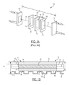
- FIG. 1A is an expanded view of a traditional PEM fuel cell stack.
- FIG. 1B is a schematic cross sectional view a fuel cell according to various embodiments of the present disclosure.
- FIG. 1C is an expanded view of an example, non-limiting PEM fuel cell stack in accordance with the present disclosure.
- FIG. 2 is a flow chart which illustrates a first method of manufacturing a fuel cell stack in accordance with the present disclosure.
- FIG. 3 is a flow chart which illustrates a second method of manufacturing a fuel cell stack in accordance with the present disclosure.
- FIG. 4 is a flow chart which illustrates a third method of manufacturing a fuel cell stack in accordance with the present disclosure.
- FIG. 5 is a flow chart which illustrates a fourth method of manufacturing a fuel cell stack in accordance with the present disclosure.
- FIG. 6 is a schematic diagram illustrating a first embodiment of a fuel cell stack assembly and the fuel cells assembled under the first method.
- FIG. 7 is a schematic diagram illustrating another fuel cell stack assembly in accordance with the first embodiment.
- FIG. 8 is a schematic diagram illustrating a fuel cell stack assembly and the fuel cells assembled under the third method.
- FIG. 9 is a schematic diagram illustrating an alternative, non-limiting example fuel cell stack assembly also in accordance with the first embodiment.
- percent, “parts of,” and ratio values are by weight; the description of a group or class of materials as suitable or preferred for a given purpose in connection with the present disclosure implies that mixtures of any two or more of the members of the group or class are equally suitable or preferred; the first definition of an acronym or other abbreviation applies to all subsequent uses herein of the same abbreviation and applies mutatis mutandis to normal grammatical variations of the initially defined abbreviation; and, unless expressly stated to the contrary, measurement of a property is determined by the same technique as previously or later referenced for the same property.
- the present disclosure provides for a method of manufacturing a fuel cell stack in accordance with various embodiments wherein the compression forces between the fuel cells within the fuel cell stack are substantially equal and/or evenly distributed along the length 31 of the fuel cell stack 32 .
- FIG. 1C an expanded view of an example non-limiting fuel stack 32 is provided wherein each fuel cell 12 in the fuel stack 32 is assembled into the fuel stack 32 according to the active area thickness 14 of each fuel cell 12 as further described in the present disclosure.
- An example, but non-limiting active area thickness 14 may fall in the range of 0.5 mm to 2 mm.
- FIG. 1B a cross sectional view of an example, non-limiting fuel cell 12 is shown in accordance with the present disclosure.
- Active area 16 is formed from first gas diffusion layer 86 , center layer 94 having both a membrane 90 and catalyst layers 92 ), second gas diffusion layer 88 .
- the fuel cell thickness 14 is shown as the distance between a first side 26 of the first gas diffusion layer 86 (shown in FIGS. 1B and 1C ) and a second side 28 of the bipolar plate 24 .
- the example fuel cell 12 includes a membrane 90 with catalyst layers 92 forming the center layer 94 .
- First sub-gasket is shown as element 84 and second sub-gasket is shown as element 96 .
- the active area thickness 14 may be defined as the distance between the second side 28 of the bipolar plate 24 and the first side 26 of the first gas diffusion layer 86 .
- the active area thickness 14 may vary from one fuel cell 12 to another fuel cell 12 due to variations in the active area—center layer 94 , first and second gas diffusion layers 86 , 88 . It is also understood that any variation that may occur in the bipolar plate 24 is minimal to none and therefore, alternatively, an alternative active area thickness 14 ′ may also be measured as the distance between the first side 26 of the first gas diffusion layer 86 to the second side 104 of the second gas diffusion layer 88 as shown. It is further understood that the active area layers 16 may be disposed on any one of the first side 106 or the second side 28 of the bipolar plate 24 . In the non-limiting example shown in FIG. 1C , the active area 16 is disposed on the 106 first side of the bipolar plate 24 . Moreover, it is also understood that the term active area thickness 14 , 14 ′ in the present disclosure could be construed to mean either thickness 14 or thickness 14 ′ as shown in the non-limiting example of FIG. 1C .
- a first manufacturing method 10 a fuel cell stack 32 ( FIG. 1C ) is shown in a flow chart.
- the first step 40 of the manufacturing method includes providing a batch of fuel cells having varying active area thicknesses.
- the second step 42 may include measuring the thickness of each fuel cell active area and sorting/directing each fuel cell into one of a first group having a nominal active area thickness, a second group having a thin active area thickness, and a third group having a thick active area thickness. It is understood that an example range for the first group (nominal active area thickness 14 ) may have a thickness tolerance 15 from about ⁇ 10 ⁇ m to about 10 ⁇ m.
- the active area for the fuel cells in the first group could have a thickness tolerance 15 which could vary from ⁇ 10 ⁇ m from the target active area thickness to as high as +10 ⁇ m relative to the target active area thickness.
- a non-limiting example range for the second group (thin active area thickness 14 where the tolerance 15 of the active area thickness may fall in the range from about ⁇ 25 ⁇ m to about ⁇ 10 ⁇ m relative to the target (or desired) active area thickness. That is, where the active area for cells in the second group could have a thickness which is so thin that it is ⁇ 25 ⁇ m from the target thickness up to ⁇ 10 ⁇ m from the target active area thickness.
- a non-limiting example range for the third group may have a tolerance 15 from about 10 ⁇ m to about 25 ⁇ m relative to the target or desired active area thickness.
- the active area for cells in this third group could have a thickness which may be as low (or thin) as 10 ⁇ m thicker than the target thickness up to 25 ⁇ m thicker than the target active area thickness.
- the third step 44 of the method includes assembling a plurality of alternating fuel cells 12 from the second (thin) and third (thick) groups onto a first fuel cell end plate as a first plurality of fuel cells until one of: (1) the target number of fuel cells have been assembled; or (2) at least one of the second (thin) and third (thick) groups is depleted of any fuel cells. It is understood that the target number 52 of fuel cells (shown in FIG. 6 ) may, but not necessarily, fall within the range of about 3 to about 100. With reference again to FIG. 6 , a schematic diagram of the fuel cells 12 and fuel cell stack 32 is shown wherein at least one of the second and third groups is depleted.
- the fourth step 46 includes providing fuel cells from the first group (nominal) to the partially assembled stack until the fuel cell stack is complete, and a fifth step 48 would be implemented which involves affixing a second fuel cell end plate to the first plurality of fuel cells and the first fuel cell end plate.
- the alternative fourth step 49 involves assembling the second fuel cell end plate to the plurality of fuel cells and the first fuel cell end plate.
- the batch 30 of fuel cells 12 (having various active area thicknesses 14 and a tolerance 15 for each active area thickness) are divided into the first group (represented by element 54 ), the second group (represented by element 56 ), and the third group (represented by element 58 ). Fuel cells 12 are then selected from the first, second and third groups 54 , 56 , 58 as described above and assembled onto a first end plate 70 as a first plurality of fuel cells 66 until the target number 52 of fuel cells is achieved. As shown, thin fuel cells 62 come from the second group 56 and thick fuel cells 64 come from the third group 58 .
- nominal fuel cells 60 from the first group 54 will be added as a second plurality 61 of fuel cells to the first plurality 66 of fuel cells until the target number 52 of fuel cells is achieved for the stack 32 .
- This additional group of nominal fuel cells 60 form second plurality of fuel cells 61 .
- the second end plate 72 is affixed onto the first and second plurality of fuel cells 66 , 61 respectively (assembled fuel cells 68 ) and the first end plate 70 as shown once the target number 52 is achieved.
- FIG. 7 illustrates the fuel cells 12 and fuel cell stack 32 ′′ implemented under the second method 10 ′′ of FIG.
- the first step 40 ′′ of the method 10 ′′ in FIG. 3 includes providing a batch of fuel cells each fuel cell in the batch of fuel cells having an active area thickness and a tolerance 15 for each active area thickness.
- the second step 42 ′′ includes measuring the thickness 14 of each fuel cell in the batch and sorting each fuel cell into one of a first group, a second group, or a third group.
- the first group of fuel cells may have an active area with a nominal thickness 14 in the range of ⁇ 10 ⁇ m to about 10 ⁇ m.
- the second group of fuel cells may have an active area with a nominal thickness 14 in the range of ⁇ 25 ⁇ m to about ⁇ 10 ⁇ m
- the third group of fuel cells may have an active area with a nominal thickness 14 in the range of 10 ⁇ m to about 25 ⁇ m.
- the third step 44 of method 10 ′′ includes assembling a first plurality of fuel cells from the first, the second and the third groups in a repeated consecutive pattern (shown as element 160 in the non-limiting example of FIG. 7 ).
- the plurality of fuel cells from the first, second and third groups are assembled onto a first fuel cell end plate until the target number of fuel cells is achieved.
- the fourth step 46 ′′ includes affixing the second fuel cell end plate to the plurality of fuel cells and the first fuel cell end plate.
- FIG. 7 a second embodiment fuel cell stack 32 and the fuel cells implemented in method 10 ′′ are shown.
- the batch 30 ′′ of fuel cells 12 (having various active area thicknesses 14 and a tolerance 15 for each active area thickness) is divided into the first group (represented by element 54 ′′), the second group (represented by element 56 ′′), and the third group (represented by element 58 ′′).
- Fuel cells 12 are then selected from the first, second and third groups 54 , 56 , 58 as described above in a repeated consecutive pattern 160 and assembled onto a first end plate 70 ′′ until the target number 52 ′′ of fuel cells is achieved.
- thin fuel cells 62 ′′ come from the second group 56 ′′ and thick fuel cells 64 ′′ come from the third group Subsequently, as described above, the second end plate 72 ′′ is then affixed onto the plurality of assembled fuel cells 68 ′′ and the first end plate 70 ′′ as shown in FIG. 7 .
- a third manufacturing method 10 ′ of the present disclosure is shown in a flow chart form.
- the fuel cells 12 and fuel cell stack 32 ′′′ under the third manufacturing method 10 ′′′ are shown in FIG. 8 of the present disclosure.
- the first step 40 ′′′ of the manufacturing method 10 ′′′ includes providing a batch of fuel cells each fuel cell having an active area thickness and a tolerance 15 for each active area thickness.
- the second step 42 ′′′ includes measuring the active area thickness of each fuel cell in the batch and sorting each fuel cell into one of a first group, a second group, and a third group.
- the first group 54 ′′′ (shown in FIG.
- the third step 44 ′′ includes randomly assembling a first plurality of fuel cells from any one or more of the first, second, and third groups on the first end plate such that the first plurality of fuel cells constitutes at least 50 percent of the target fuel cell number 52 .
- the fourth step includes selectively assembling a second plurality of fuel cells for the stack from any one of the first, second, and third groups so that 100% of the target fuel cell numbers in the stack is achieved and target height (element 74 in FIG. 8 ) is achieved
- the fifth step 48 ′′′ includes affixing a second fuel cell end plate to the plurality of assembled fuel cells and the first fuel cell end plate. It is understood that, with respect to all embodiments of the present disclosure, an example but non-limiting target (or desired) fuel cell number may fall within the range of 3 fuel cells to 100 fuel cells.
- the batch 30 ′′′ of fuel cells 12 (having an active area thickness 14 , 14 ′ and a tolerance 15 for each fuel cell in the batch 30 ) are divided into the first group (represented by element 54 ′′′), the second group (represented by element 56 ′), and the third group (represented by element 58 ′′′). Fuel cells 12 are then selected from the first, second and third groups 54 ′′′, 56 ′′′, 58 ′′′ as described above and assembled onto a first end plate 70 ′′′ such that the first plurality 66 ′′′ of fuel cells constitutes at least 50% of the target number 52 ′′′ of fuel cells.
- Nominal fuel cells 60 m come from first group 54 ′′′, thin fuel cells 62 ′′′ come from the second group 56 ′′′ and thick fuel cells 64 ′′′ come from the third group 58 ′′′.
- a second plurality of fuel cells 61 ′′′ from at least the first, second and third groups 54 ′′′, 56 ′′′, are selectively assembled to the first plurality of fuel cells 66 ′′′′ in a very careful manner until the target number and target height 74 (shown in FIG. 8 ) are achieved.
- the step of selectively assembling includes the step of determining a remaining target height 75 each time a new fuel cell is added to the second plurality 61 ′′′ of fuel cells.
- the target height 74 may, but not necessarily fall within the range of about 2 feet to about 4 feet. However, it is understood that the fuel cells must be assembled within +3 mm or ⁇ 3 mm of the target height. As each new fuel cell is added to the second plurality of fuel cells 61 ′′′, the remaining target height 75 progressively decreases to zero. As described above, once the target height 75 is achieved and target number 52 ′′′′ are achieved, the second end plate 72 ′′′ may be affixed the plurality of assembled fuel cells 68 ′′′ and the first end plate 70 ′′′ as shown in FIG. 8 . It is understood that with respect to all embodiments implementing a target height, an example, non-limiting predetermined target height may fall in the range from about 1 inch to about 4 feet.
- the first step 40 ′′′′ of the manufacturing method includes providing a batch of fuel cells each fuel cell having an active area thickness 14 and a tolerance 15 for each active area thickness.
- the second step 42 ′′′′ includes measuring the active area thickness of each fuel cell in the batch and sorting/directing each fuel cell into one of a first group, a second group, and a third group.
- the first group is defined by one or more fuel cells which have an active area thickness 14 which falls in the tolerance 15 which may range from ⁇ 10 ⁇ m to about 10 ⁇ m of the target active area thickness.
- An example, but non-limiting active area thickness 14 may fall in the range of 0.5 mm to 2 mm.
- the second group of fuel cells have an active area with a nominal thickness 14 which falls in the range of ⁇ 25 ⁇ m to about ⁇ 10 ⁇ m relative to the target or desired active area thickness
- the third group of fuel cells have an active area with an active area thickness 14 in the tolerance range of 10 ⁇ m to about 25 ⁇ m greater than the target active area thickness.
- the third step 44 ′′′′ includes assembling a first plurality of fuel cells from the first group on a first fuel cell end plate until one of: (1) the target number of fuel cells is achieved, or (2) the first group of fuel cells is depleted of nominal fuel cells.
- the fourth step 48 ′′′′ includes affixing a second fuel cell end plate to the first plurality of fuel cells and the first fuel cell end plate.
- the alternative fourth step 46 ′′′′ includes providing one or more fuel cells from at least one of the second group and third group until the target fuel cell stack number is achieved and then the alternative fifth step 49 ′′′′ (following from step 46 ′′′) includes affixing a second fuel cell end plate to the plurality of fuel cells and the first fuel cell end plate. It is preferable, but not necessary, to alternate between thick and thin fuel cells (when both are used) in the second plurality 61 ′′′′ of fuel cells to ensure a fairly even distribution of compression forces 35 across the stack 32 .
- example fuel cell stacks 80 and 82 and fuel cells 12 implemented under the method 10 ′′′′ of FIG. 5 are shown.
- the batch 30 ′′′′ of fuel cells 12 (having various active area thicknesses 14 ) is divided into the first group (represented by element 54 ′′′′), the second group (represented by element 56 ′′′′), and the third group (represented by element 58 ′′′′).
- Nominal fuel cells 60 ′′′′ from the first group 54 ′′′′ are assembled as a first plurality of fuel cells 66 ′′′′ onto a first end plate 70 ′′′ as described above until either: (1) the target number 52 ′′′′ of fuel cells is achieved; or (2) the first group 54 ′′′′ is depleted of all nominal fuel cells 60 ′′′′.
- the second end plate 72 ′′′′ is affixed to the first plurality of fuel cells 66 ′′′′ and the first end plate 70 ′′′′ thereby forming fuel cell stack 80 .
- the first group 54 ′′′′ is depleted of all nominal fuel cells 60 ′′′′ before the target number is achieved, then fuel cells 62 ′′′′, 64 ′′′′ will be added from the second and third groups (preferably in an alternating fashion) as the second plurality of fuel cells 61 ′′′′ until the target number 52 ′′′′ of fuel cells is achieved.
- the second end plate 72 ′′′′ is affixed to the target number 52 ′′′′ of fuel cells and the first end plate 70 ′′ thereby forming fuel cell stack 82 .
- a fuel cell stack assembly of the present disclosure is shown as elements 32 and 33 in FIG. 6 , element 32 ′′ in FIG. 7 , and element 80 in FIG. 9 .
- a fuel cell stack assembly of the present disclosure may include a first end plate 70 , 70 ′′, 70 ′′′′, a second end plate, 72 , 72 ′′, 72 ′′′′; and a first plurality 66 , 66 ′′, and 66 ′′ of fuel cells disposed between the first and second end plates as shown in FIGS. 6, 7, and 9 .
- the first plurality 66 , 66 ′′, and 66 ′′′′ of fuel cells may define a repeating first pattern 67 , 67 ′′, 67 ′′′′ of fuel cells being at least one of a nominal fuel cell 60 , a thick fuel cell 64 and a thin fuel cell 62 .
- Each nominal fuel cell 60 , 60 ′′, 60 ′′′′ may be selected from a first group 54 , 54 ′′, 54 ′′′′
- each thick fuel cell 64 , 64 ′′, 64 ′′′′ may be selected from a third group 58 , 58 ′′, 58 ′′′′
- each thin fuel cell 62 , 62 ′′, 62 ′′′′ may be selected from a second group, 56 , 56 ′′, 56 ′′′′.
- the first pattern 67 , 67 ′′, 67 ′′′′ which may be repeated in the first plurality of fuel cells may include a thick fuel cell 64 adjacent to a thin fuel cell 62 as shown in FIG. 6 in fuel stack assembly 33 .
- An alternative first pattern which may be repeated in the first plurality of fuel cells may be a first nominal fuel cell 60 ′′′′ adjacent to a second nominal fuel cell 60 ′′′′.
- another alternative first pattern which may be repeated in the first plurality of fuel cells may be a thin fuel cell 62 ′′ disposed between a thick fuel cell 64 ′′ and a nominal fuel cell 60 ′′ as shown in FIG. 7 .
- Each fuel cell 12 in the first plurality 66 , 66 ′′, and 66 ′′′′ of fuel cells may define an active area thickness 14 , 14 ′ (shown in FIG. 1B ) having a tolerance 15 (shown in FIG. 1B ) wherein the tolerance 15 for each thin fuel cell 62 , 62 ′′, 62 ′′′′ falls in a range of about ⁇ 25 ⁇ m to about ⁇ 10 ⁇ m, the tolerance 15 for each thick fuel cell 64 , 64 ′′, 64 ′′′′ falls in a range of about 10 ⁇ m to about 25 ⁇ m, and the tolerance 15 for each nominal fuel cell 40 , 40 ′′, 40 ′′′′ falls in a range of about ⁇ 10 ⁇ m to about 10 ⁇ m.
- the fuel cell stack assembly of the present disclosure may further include a second plurality of fuel cells (shown as element 61 in FIG. 6 , and element 61 ′′′′ in FIG. 9 ) wherein the second plurality 61 , 61 ′′ of fuel cells defines a second pattern (shown as element 69 in example FIG. 6 and shown as element 69 ′′′′ in example FIG. 9 ) of fuel cells.
- the second pattern 69 may be defined by two thin fuel cells next to a thick fuel cell.
- the second pattern 69 may be defined by two nominal fuel cells.
- the second pattern 69 , 69 ′′′′ in the second plurality 61 of fuel cells may be different from the first pattern 67 , 67 ′′′′′ in the first plurality 66 , 66 ′′′′ of fuel cells.
- the second plurality 61 , 61 ′′′′ of fuel cells may be disposed between the first plurality 66 , 66 ′′′′ of fuel cells and the second end plate 70 , 70 ′′′′. Again, it is understood that each fuel cell 12 in the first and second plurality 61 , 61 ′′′′ of fuel cells of FIGS.
- the active area thickness 14 ′ may be defined by a distance between a first surface 26 of a first sub-gasket 84 and a second surface 104 of a second sub-gasket 96 as shown in FIG. 1B , Alternatively, active area thickness may also be defined as element 14 which spans the distance from the first surface 26 of a first sub-gasket 84 and a second surface 28 of bipolar plate 24 as shown in FIG. 1B .
Landscapes
- Life Sciences & Earth Sciences (AREA)
- Engineering & Computer Science (AREA)
- Manufacturing & Machinery (AREA)
- Sustainable Development (AREA)
- Sustainable Energy (AREA)
- Chemical & Material Sciences (AREA)
- Chemical Kinetics & Catalysis (AREA)
- Electrochemistry (AREA)
- General Chemical & Material Sciences (AREA)
- Fuel Cell (AREA)
Abstract
Description
Claims (18)
Priority Applications (3)
| Application Number | Priority Date | Filing Date | Title |
|---|---|---|---|
| US15/586,522 US10468707B2 (en) | 2017-05-04 | 2017-05-04 | Fuel cell stack assembly |
| CN201810377515.1A CN108808055B (en) | 2017-05-04 | 2018-04-25 | Fuel cell stack assembly |
| DE102018110515.0A DE102018110515A1 (en) | 2017-05-04 | 2018-05-02 | Fuel cell stack assembly |
Applications Claiming Priority (1)
| Application Number | Priority Date | Filing Date | Title |
|---|---|---|---|
| US15/586,522 US10468707B2 (en) | 2017-05-04 | 2017-05-04 | Fuel cell stack assembly |
Publications (2)
| Publication Number | Publication Date |
|---|---|
| US20180323464A1 US20180323464A1 (en) | 2018-11-08 |
| US10468707B2 true US10468707B2 (en) | 2019-11-05 |
Family
ID=63895697
Family Applications (1)
| Application Number | Title | Priority Date | Filing Date |
|---|---|---|---|
| US15/586,522 Active 2037-11-16 US10468707B2 (en) | 2017-05-04 | 2017-05-04 | Fuel cell stack assembly |
Country Status (3)
| Country | Link |
|---|---|
| US (1) | US10468707B2 (en) |
| CN (1) | CN108808055B (en) |
| DE (1) | DE102018110515A1 (en) |
Citations (2)
| Publication number | Priority date | Publication date | Assignee | Title |
|---|---|---|---|---|
| US6833211B1 (en) * | 2003-10-20 | 2004-12-21 | Utc Fuel Cells, Llc | Fuel cell stack having a reduced volume |
| US20080206617A1 (en) * | 2005-04-12 | 2008-08-28 | Nissan Motor Co., Ltd. | Fuel Cell Separators |
Family Cites Families (12)
| Publication number | Priority date | Publication date | Assignee | Title |
|---|---|---|---|---|
| US4728585A (en) * | 1986-12-24 | 1988-03-01 | International Fuel Cells Corporation | Fuel cell stack with combination end-pressure plates |
| US6686080B2 (en) * | 2000-04-18 | 2004-02-03 | Plug Power Inc. | Fuel cell systems |
| JP3673155B2 (en) * | 2000-08-11 | 2005-07-20 | 本田技研工業株式会社 | Fuel cell stack |
| US6503653B2 (en) * | 2001-02-23 | 2003-01-07 | General Motors Corporation | Stamped bipolar plate for PEM fuel cell stack |
| DE10392584B4 (en) * | 2002-04-30 | 2021-05-12 | General Motors Corp. (N.D.Ges.D. Staates Delaware) | Electrochemical fuel cell stack |
| US7226689B2 (en) * | 2003-06-20 | 2007-06-05 | Ballard Power Systems Inc. | Method of making a membrane electrode assembly for electrochemical fuel cells |
| KR100980995B1 (en) * | 2007-06-19 | 2010-09-07 | 현대자동차주식회사 | Intelligent Electrode Membrane for Fuel Cell |
| US8822100B2 (en) * | 2011-11-14 | 2014-09-02 | GM Global Technology Operations LLC | Method of controlling thickness of form-in-place sealing for PEM fuel cell stacks |
| US9076998B2 (en) * | 2012-09-12 | 2015-07-07 | GM Global Technology Operations LLC | Fuel-cell membrane-subgasket assemblies comprising coated subgaskets, and fuel-cell assemblies and fuel-cell stacks comprising the fuel-cell membrane subgasket assemblies |
| GB2509158A (en) * | 2012-12-21 | 2014-06-25 | Intelligent Energy Ltd | Fuel Cell Stack Assembly and Method of Assembly |
| CN103779586B (en) * | 2014-01-13 | 2016-01-20 | 江苏绿遥燃料电池系统制造有限公司 | A kind of fuel cell end plate |
| RU2677269C2 (en) * | 2014-03-12 | 2019-01-16 | Серес Интеллекчуал Проперти Компани Лимитед | Fuel cell stack arrangement |
-
2017
- 2017-05-04 US US15/586,522 patent/US10468707B2/en active Active
-
2018
- 2018-04-25 CN CN201810377515.1A patent/CN108808055B/en active Active
- 2018-05-02 DE DE102018110515.0A patent/DE102018110515A1/en active Granted
Patent Citations (2)
| Publication number | Priority date | Publication date | Assignee | Title |
|---|---|---|---|---|
| US6833211B1 (en) * | 2003-10-20 | 2004-12-21 | Utc Fuel Cells, Llc | Fuel cell stack having a reduced volume |
| US20080206617A1 (en) * | 2005-04-12 | 2008-08-28 | Nissan Motor Co., Ltd. | Fuel Cell Separators |
Also Published As
| Publication number | Publication date |
|---|---|
| CN108808055A (en) | 2018-11-13 |
| US20180323464A1 (en) | 2018-11-08 |
| DE102018110515A1 (en) | 2018-11-08 |
| CN108808055B (en) | 2021-11-30 |
Similar Documents
| Publication | Publication Date | Title |
|---|---|---|
| US8617770B2 (en) | Electrodes containing oxygen evolution reaction catalysts | |
| CN101420043B (en) | Fuel cell stack with asymmetric diffusion media on anode and cathode | |
| EP3509148A1 (en) | Redox flow secondary battery and electrode thereof | |
| US7745063B2 (en) | Fuel cell stack | |
| WO2003096462A8 (en) | Electrochemical fuel cell comprised of a series of conductive compression gaskets and method of manufacture | |
| JP4977129B2 (en) | Conductive fluid distribution plate for fuel cells | |
| DE102013217759A1 (en) | Fuel cell membrane sub-seal assemblies with coated sub-gaskets as well as fuel cell assemblies and fuel cell stacks with the fuel cell membrane sub-seal assemblies | |
| EP1484810A1 (en) | Method for manufacturing polymer electrolyte type fuel cell | |
| JP2001057218A (en) | Polymer electrolyte fuel cell and method of manufacturing the same | |
| US8623573B2 (en) | Porous, electrically conductive fluid distribution plate for fuel cells | |
| US20060105159A1 (en) | Gas diffusion medium with microporous bilayer | |
| US10276878B2 (en) | Coated aluminum bipolar plate for fuel cell applications | |
| US20100035125A1 (en) | Layered electrode for electrochemical cells | |
| US9705139B2 (en) | Printed multi-function seals for fuel cells | |
| US20060257712A1 (en) | Hydrophilic, electrically conductive fluid distribution plate for fuel cell | |
| US9362574B2 (en) | PEM fuel cell seal design and method for manufacture | |
| US9246178B2 (en) | Method to minimize the impact of shunt currents through aqueous based coolants on PEM fuel cell bipolar plates | |
| CN108461796B (en) | Fuel cell end plate unit and cell stack | |
| US10468707B2 (en) | Fuel cell stack assembly | |
| US10388979B2 (en) | Method of manufacturing a fuel cell stack | |
| US8329356B2 (en) | Fuel cell microporous layer including particles with a controlled pore size distribution | |
| US20240079607A1 (en) | Fuel Cell Gas Diffusion Layers | |
| US7998631B2 (en) | Method to reduce/eliminate shunt current corrosion of wet end plate in PEM fuel cells | |
| JP6356436B2 (en) | Electrolyte membrane / electrode structure | |
| JP2006147522A (en) | Method for producing membrane electrode assembly, fuel cell, and method for producing conductive particle layer |
Legal Events
| Date | Code | Title | Description |
|---|---|---|---|
| AS | Assignment |
Owner name: GM GLOBAL TECHNOLOGY OPERATIONS LLC, MICHIGAN Free format text: ASSIGNMENT OF ASSIGNORS INTEREST;ASSIGNORS:YANG, XI;XI, LIANG;ROCK, JEFFREY A;AND OTHERS;REEL/FRAME:042238/0725 Effective date: 20170503 |
|
| STPP | Information on status: patent application and granting procedure in general |
Free format text: NON FINAL ACTION MAILED |
|
| STPP | Information on status: patent application and granting procedure in general |
Free format text: RESPONSE TO NON-FINAL OFFICE ACTION ENTERED AND FORWARDED TO EXAMINER |
|
| STPP | Information on status: patent application and granting procedure in general |
Free format text: NOTICE OF ALLOWANCE MAILED -- APPLICATION RECEIVED IN OFFICE OF PUBLICATIONS |
|
| STPP | Information on status: patent application and granting procedure in general |
Free format text: AWAITING TC RESP, ISSUE FEE PAYMENT RECEIVED |
|
| STPP | Information on status: patent application and granting procedure in general |
Free format text: PUBLICATIONS -- ISSUE FEE PAYMENT VERIFIED |
|
| STCF | Information on status: patent grant |
Free format text: PATENTED CASE |
|
| MAFP | Maintenance fee payment |
Free format text: PAYMENT OF MAINTENANCE FEE, 4TH YEAR, LARGE ENTITY (ORIGINAL EVENT CODE: M1551); ENTITY STATUS OF PATENT OWNER: LARGE ENTITY Year of fee payment: 4 |