US10464768B2 - Conveying apparatus - Google Patents
Conveying apparatus Download PDFInfo
- Publication number
- US10464768B2 US10464768B2 US15/882,208 US201815882208A US10464768B2 US 10464768 B2 US10464768 B2 US 10464768B2 US 201815882208 A US201815882208 A US 201815882208A US 10464768 B2 US10464768 B2 US 10464768B2
- Authority
- US
- United States
- Prior art keywords
- medium
- feeding
- conveying apparatus
- conveyance
- driving shaft
- Prior art date
- Legal status (The legal status is an assumption and is not a legal conclusion. Google has not performed a legal analysis and makes no representation as to the accuracy of the status listed.)
- Expired - Fee Related, expires
Links
- 230000004044 response Effects 0.000 claims description 14
- 230000008859 change Effects 0.000 claims description 7
- 238000003825 pressing Methods 0.000 description 17
- 230000000694 effects Effects 0.000 description 10
- 230000002401 inhibitory effect Effects 0.000 description 5
- 239000002783 friction material Substances 0.000 description 3
- 239000000463 material Substances 0.000 description 3
- 230000007246 mechanism Effects 0.000 description 3
- 239000000470 constituent Substances 0.000 description 2
- 238000010586 diagram Methods 0.000 description 2
- 230000006872 improvement Effects 0.000 description 2
- 230000009471 action Effects 0.000 description 1
- 239000012790 adhesive layer Substances 0.000 description 1
- 238000005520 cutting process Methods 0.000 description 1
- 230000007423 decrease Effects 0.000 description 1
- 230000005489 elastic deformation Effects 0.000 description 1
- 229920001971 elastomer Polymers 0.000 description 1
- 238000005259 measurement Methods 0.000 description 1
- 238000000034 method Methods 0.000 description 1
- 238000002360 preparation method Methods 0.000 description 1
- 238000005096 rolling process Methods 0.000 description 1
- 239000005060 rubber Substances 0.000 description 1
- 239000000758 substrate Substances 0.000 description 1
- 238000004804 winding Methods 0.000 description 1
Images


Classifications
-
- B—PERFORMING OPERATIONS; TRANSPORTING
- B65—CONVEYING; PACKING; STORING; HANDLING THIN OR FILAMENTARY MATERIAL
- B65H—HANDLING THIN OR FILAMENTARY MATERIAL, e.g. SHEETS, WEBS, CABLES
- B65H23/00—Registering, tensioning, smoothing or guiding webs
- B65H23/04—Registering, tensioning, smoothing or guiding webs longitudinally
- B65H23/18—Registering, tensioning, smoothing or guiding webs longitudinally by controlling or regulating the web-advancing mechanism, e.g. mechanism acting on the running web
- B65H23/188—Registering, tensioning, smoothing or guiding webs longitudinally by controlling or regulating the web-advancing mechanism, e.g. mechanism acting on the running web in connection with running-web
- B65H23/1888—Registering, tensioning, smoothing or guiding webs longitudinally by controlling or regulating the web-advancing mechanism, e.g. mechanism acting on the running web in connection with running-web and controlling web tension
-
- B—PERFORMING OPERATIONS; TRANSPORTING
- B65—CONVEYING; PACKING; STORING; HANDLING THIN OR FILAMENTARY MATERIAL
- B65H—HANDLING THIN OR FILAMENTARY MATERIAL, e.g. SHEETS, WEBS, CABLES
- B65H20/00—Advancing webs
- B65H20/02—Advancing webs by friction roller
-
- B—PERFORMING OPERATIONS; TRANSPORTING
- B65—CONVEYING; PACKING; STORING; HANDLING THIN OR FILAMENTARY MATERIAL
- B65H—HANDLING THIN OR FILAMENTARY MATERIAL, e.g. SHEETS, WEBS, CABLES
- B65H23/00—Registering, tensioning, smoothing or guiding webs
- B65H23/04—Registering, tensioning, smoothing or guiding webs longitudinally
- B65H23/06—Registering, tensioning, smoothing or guiding webs longitudinally by retarding devices, e.g. acting on web-roll spindle
- B65H23/10—Registering, tensioning, smoothing or guiding webs longitudinally by retarding devices, e.g. acting on web-roll spindle acting on running web
-
- B—PERFORMING OPERATIONS; TRANSPORTING
- B65—CONVEYING; PACKING; STORING; HANDLING THIN OR FILAMENTARY MATERIAL
- B65H—HANDLING THIN OR FILAMENTARY MATERIAL, e.g. SHEETS, WEBS, CABLES
- B65H2404/00—Parts for transporting or guiding the handled material
- B65H2404/10—Rollers
- B65H2404/14—Roller pairs
Definitions
- the present disclosure relates to a conveying apparatus that conveys a medium while unwinding a roll of medium.
- a conveying apparatus that conveys a medium while unwinding a roll of medium is used in a variety of fields. This type of conveying apparatus supplies a medium to external apparatuses that vary depending on intended uses.
- One embodiment of the present disclosure is to provide a conveying apparatus that can obtain excellent conveying performance.
- An aspect is a conveying apparatus that includes: a shaft member extending in a first direction and rotatable about a rotation axis parallel with the first direction; a feeding-out member slidably supported on the shaft member in the first direction and retaining a roll of medium, and configured to rotate in a medium conveyance direction with rotation of the shaft member while being movable in the first direction along the shaft member; a conveyance member configured to convey the medium by drawing out the medium from the feeding-out member along a medium conveyance route; a load applying member that applies a load on the feeding-out member in a direction opposed to the medium conveyance direction; a guide member provided between the feeding-out member and the conveyance member in the second direction and at one end portion of the medium conveyance route in the first direction, and configured to restrict movement of the medium in the first direction; and an inclination member inclined with respect to the first direction and in contact with the medium between the feeding-out member and the conveyance member in the medium conveyance route, thereby making a conveyed distance of the medium
- the feeding-out member rotates about the shaft member with the applied load while moving along the shaft member.
- excellent conveying performance can be obtained.
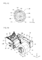
- FIG. 1 is a perspective view illustrating a configuration of a conveying apparatus according to one or more embodiments
- FIG. 2 is a plan (front) view of a conveying unit in the conveying apparatus illustrates in FIG. 1 ;
- FIG. 3 is a plan (side) view of the conveying unit in the conveying apparatus illustrates in FIG. 1 ;
- FIG. 4 is a plan (side) view of the conveying unit in the conveying apparatus illustrates in FIG. 1 ;
- FIG. 5 is a perspective view of a support unit in the conveying apparatus illustrates in FIG. 1 ;
- FIG. 6 is a plan (top) view of a feeding-out unit in the conveying apparatus illustrates in FIG. 1 ;
- FIG. 7 is a perspective view of a feeding-out core in the feeding-out unit illustrates in FIG. 6 ;
- FIG. 8 is a cross-sectional view of the feeding-out unit taken along the A-A line in FIG. 6 ;
- FIG. 9 is a cross-sectional view of the feeding-out unit taken along the B-B line in FIG. 6 ;
- FIG. 10 is a perspective view of a friction member in the conveying apparatus illustrates in FIG. 1 ;
- FIG. 11 is a plan (front) view of a cap in the conveying apparatus illustrates in FIG. 1 ;
- FIG. 12 is a perspective view of the cap in the conveying apparatus illustrates in FIG. 1 ;
- FIG. 13 is a cross-sectional view of the feeding-out unit in the conveying apparatus illustrates in FIG. 1 ;
- FIG. 14 is a perspective view of the conveying apparatus for the purpose of explaining how the conveying apparatus illustrates in FIG. 1 works;
- FIG. 15 is a plan (top) view of the conveying apparatus in operation for the purpose of explaining how tensile forces are generated while the conveying apparatus is in operation in a case where the outer diameter of the roll R is large;
- FIG. 16 is a plan (side) view of the conveying apparatus illustrated in FIG. 15 ;
- FIG. 17 is a plan (top) view of the conveying apparatus in operation for the purpose of explaining how tensile forces are generated while the conveying apparatus is in operation in a case where the outer diameter of the roll R is small;
- FIG. 18 is a plan (side) view of the conveying apparatus illustrated in FIG. 17 ;
- FIG. 19 is a perspective view of a modified example of the feeding-out core
- FIG. 20 is a magnified perspective view of a configuration of a part X in FIG. 19 ;
- FIG. 21 is a perspective view illustrating a configuration of an adjustment dial
- FIG. 22 is a plan (front) view of the adjustment dial illustrated in FIG. 21 ;
- FIG. 23 is a plan (top) view of the feeding-out unit that includes a feeding-out core according to the modified example
- FIG. 24 is a cross-sectional view of the feeding-out unit taken along the C-C line in FIG. 23 ;
- FIG. 25 is a diagram illustrating a result of a conveyance test using a conveying apparatus according to Experimental Example 1;
- FIG. 26 is a diagram illustrating a result of a conveyance test using a conveying apparatus according to Experimental Example 2.
- the conveying apparatus discussed herein is a conveying apparatus that uses a roll of medium (hereinafter referred to as a “roll”) and continuously conveys the medium while unwinding the roll of medium.
- roll a roll of medium
- the intended use of the conveying apparatus is not limited to a particular one.
- This conveying apparatus is used to supply a medium to an external apparatus such as an image forming apparatus (a so-called printer).
- the material of the medium is not limited to a particular one, but for example is one or more of paper, film, laminated paper, laminated film and the like.
- This medium may be a laminate including one or more types of paper, a laminate including one or more types of films, or a laminate including one or more types of paper and one or more types of films.
- FIG. 1 illustrates a perspective configuration of the conveying apparatus.
- FIG. 1 illustrates the configuration of the conveying apparatus with no roll R (see FIG. 14 ) attached to the conveying apparatus.
- This roll R is a roll of medium M.
- the conveying apparatus includes, for example, a feeding-out unit 10 , a conveying unit 20 , and a support unit 30 .
- the feeding-out unit 10 mainly retains the roll R, and continuously feeds out the medium M from the roll R to the conveying unit 20 .
- a direction (Y-axis direction) in which the medium M is conveyed from the feeding-out unit 10 and the conveying unit 20 is hereinafter referred to as a “conveyance direction.”
- a direction (X-axis direction) that intersects the conveyance direction, in other words, a direction defined by the width of the medium M, will be hereinafter referred to as a “width direction.”
- the conveyance direction is a “second direction”
- the width direction is a “first direction.”
- the conveying unit 20 mainly conveys the medium M fed out from the feeding-out unit 10 , and delivers the medium M to the outside.
- the medium M conveyed by the conveying apparatus is supplied to, for example, the above-mentioned external apparatus such as the image forming apparatus.
- the support unit 30 mainly supports the feeding-out unit 10 , and drives the feeding-out unit 10 .
- the support unit 30 includes, for example, a support plate 31 , and a support lid 32 attached to the support plate 31 .
- the support unit 30 extends in the conveyance direction, for example.
- the feeding-out unit 10 is placed, for example, at a location near one end portion of the support unit 30 , and is drivably supported by the one end portion of the support unit 30 .
- the configurations of the feeding-out unit 10 , the conveying unit 20 and the support unit 30 are described later (see FIGS. 2 to 13 ).
- FIG. 1 is referred to whenever deemed necessary.
- FIG. 2 illustrates a plan (front) configuration of the conveying unit 20 illustrated in FIG. 1 .
- FIG. 4 illustrates a plan (side) configuration of the conveying unit 20 illustrated in FIG. 1 .
- the conveying unit 20 includes, for example, a conveyance main body 21 , a steering roller 22 , a feed roller 23 , a side guide 24 and a cutter 25 .
- the steering roller 22 , the feed roller 23 and the side guide 24 correspond respectively to an “inclination member,” a “conveyance member,” and a “guide member” of the present disclosure.
- the conveyance main body 21 is mainly a base that supports the steering roller 22 , the feed roller 23 , the side guide 24 , the cutter 25 and the like.
- the conveyance main body 21 includes a conveyance surface 21 M, for example, in the middle of a conveyance route of the medium M, more specifically, between the steering roller 22 and the feed roller 23 .
- the conveyance surface 21 M guides the medium M from the steering roller 22 to the feed roller 23 .
- the condition of the conveyance surface 21 M is not limited to a particular one, and may be a flat surface, curved surface, or a surface including both a flat surface and a curved surface.
- FIG. 1 illustrates the conveyance surface 21 M that is, for example, a curved-out surface.
- the steering roller 22 mainly adjusts tensile forces on the medium M while conveying the medium M.
- the steering roller 22 is placed on the conveyance route of the medium M fed out from the feeding-out unit 10 .
- the steering roller 22 is placed between the feeding-out unit 10 and the feed roller 23 , more specifically, between the feeding-out unit 10 and the side guide 24 .
- the steering roller 22 extends, for example, in the width direction (X-axis direction), and is rotatable around the X axis.
- a height-direction (Z-axis-direction) location of the steering roller 22 is not limited to a particular one.
- the steering roller 22 is placed, for example, in a location lower than the side guide 24 .
- components including the word “roller” in their names extend in the width direction (X-axis direction), and are rotatable around the X axis, like the steering roller 22 .
- a shaft 27 is supported by a pair of arms 26 , and is penetrated through the steering roller 22 .
- the pair of arms 26 are placed facing each other with the conveyance route of the medium M interposed in between.
- the shaft 27 extends in the width direction, for example.
- the steering roller 22 is rotatable, for example, around the shaft 27 .
- the shaft 27 is supported, for example, by end portions of the pair of arms 26 .
- the other end portions of the pair of arms 26 are turnably (swingably) supported, for example, by the shaft 28 inserted through the conveyance main body 21 .
- the steering roller 22 is movable vertically in the height direction (Z-axis direction), for example, using the turn action of the pair of arms 26 . Accordingly, while the medium M is being conveyed, the tensile forces on the medium M are adjusted using the vertical movement of the steering roller 22 .
- the steering roller 22 inclines as illustrated in FIG. 2 . That is to say, the extending direction of the steering roller 22 inclines to the horizontal direction (X axis).
- the steering roller 22 inclines such that: the conveyed distance of the medium M becomes shorter toward a first widthwise side of the conveyance route of the medium M, that is to say, a first side of the conveyance route near the side guide 24 (the right in FIG. 2 ); and the conveyed distance of the medium M becomes longer toward a second widthwise end of the conveyance route, that is to say, a second side of the conveyance route far from the side guide 24 (the left in FIG. 2 ).
- the steering roller 22 inclines such that the steering roller 22 becomes higher toward the first side of the conveyance route near the side guide 24 ; and the steering roller 22 becomes lower toward the second side of the conveyance route far from the side guide 24 .
- An inclination angle ⁇ of the steering roller 22 is not limited to a particular one, but is, for example, within a range of approximately 0.1 degrees to approximately 0.5 degrees. This inclination angle ⁇ is defined by the extending direction of the steering roller 22 and the horizontal direction (X-axis direction).
- the reason for the inclination of the steering roller 22 is that: a tensile force generated on the medium M on the first side near the side guide 24 and a tensile force generated on the medium M on the second side far from the side guide 24 are deliberately made different from each other; and using the difference in the tensile force, the medium M is guided in a direction closer to the side guide 24 while the medium M is being conveyed.
- the principle for the guiding of the medium M in the direction closer to the side guide 24 is discussed later (see FIGS. 15 and 16 ).
- the feed roller 23 mainly conveys the medium M fed out from the feeding-out unit 10 . Particularly, the feed roller 23 grips the medium M conveyed via the steering roller 22 , and supplies the medium M to the cutter 25 .
- the feed roller 23 is placed downstream of the steering roller 22 in the conveyance direction. To put it more specifically, the feed roller 23 is placed downstream of the side guide 24 .
- a height-direction (Z-axis-direction) location of the feed roller 23 is not limited to a particular one.
- the feed roller 23 is placed, for example, at a location higher than the steering roller 22 .
- the feed roller 23 includes a pair of rollers placed with the medium M interposed in between, in order to grip the medium M.
- the feed roller 23 is rotated by driving force (rotation force) of a motor 29 via gears G.
- the side guide 24 mainly restricts movement of the medium M in the width direction.
- the side guide 24 is placed between the feeding-out unit 10 and the feed roller 23 . To put it more specifically, the side guide 24 is placed between the steering roller 22 and the feed roller 23 .
- the side guide 24 is placed at one widthwise side of the conveyance route of the medium M.
- the location of the side guide 24 is not limited to a particular one, as long as the location is at the one widthwise side of the conveyance route of the medium M.
- the side guide 24 is placed, for example, at the right of the conveyance route of the medium M (near the support unit 30 ).
- the three-dimensional shape of the side guide 24 is not limited to a particular one, as long as the shape enables the side guide 24 to restrict the movement of the medium M in the width direction.
- the three-dimensional shape of the side guide 24 is, for example, a substantially plate shape that includes a guide surface 24 M extending in the conveyance direction.
- the cutter 25 mainly cuts the medium M supplied from the feed roller 23 . Thereby, the belt-shaped medium M continuously fed out from the roll R is cut into sheets.
- the cutter 25 is placed, for example, downstream of the feed roller 23 in the conveyance direction. Furthermore, the cutter 25 includes, for example, a cutter blade that cuts the medium M.
- FIG. 1 is referred to whenever deemed necessary.
- FIG. 5 illustrates a perspective configuration of the support unit 30 illustrated in FIG. 1 .
- FIG. 5 illustrates the configuration of the support unit 30 (the support plate 31 and the support lid 32 ) with the support lid 32 removed from the support unit 30 .
- FIG. 5 further illustrates a part (a driving shaft 11 ) of the feeding-out unit 10 for the purpose of making a connecting relationship between the feeding-out unit 10 and the support unit 30 easy to understand.
- the support unit 30 includes, for example, a motor gear 33 , a deceleration gear 34 , idle gears 35 , 36 , a driving gear 37 , and a torque limiter 38 .
- the motor gear 33 , the deceleration gear 34 , the idle gears 35 , 36 and the driving gear 37 are rotatably supported, for example, by the support plate 31 .
- the motor gear 33 , the deceleration gear 34 , the idle gears 35 , 36 and the driving gear 37 are arranged in this order, for example.
- the driving gear 37 is rotatable, for example, using driving force (rotation force) of the motor gear 33 via the deceleration gear 34 and the idle gears 35 , 36 .
- the driving gear 37 mainly rotates the driving shaft 11 .
- the driving shaft 11 is rotatable, for example, in response to the rotation of the driving gear 37 .
- the torque limiter 38 serving as a load applying member, mainly gives torque (load) to the rotation of the driving shaft 11 .
- the torque limiter 38 is attached, for example, to the driving gear 37 .
- One end portion of the driving shaft 11 is fixed, for example, to the torque limiter 38 using a fixing pin 39 .
- FIGS. 1 and 5 are referred to whenever deemed necessary.
- FIG. 6 illustrates a plan (top) configuration of the feeding-out unit 10 illustrated in FIG. 1 .
- FIG. 7 illustrates a perspective configuration of a feeding-out core 12 (also referred to as a “roll core 12 ”) illustrated in FIG. 6 .
- FIG. 8 illustrates a cross-sectional configuration of the feeding-out unit 10 taken along the A-A line in the FIG. 6 .
- FIG. 9 illustrates a cross-sectional configuration of the feeding-out unit 10 taken along the B-B line in the FIG. 6 .
- FIGS. 6, 8 and 9 illustrate the configuration of the feeding-out unit 10 with a cap 13 removed from the feeding-out unit 10 as illustrated in FIG. 1 .
- FIG. 10 illustrates a perspective configuration of a friction member 17 .
- FIGS. 11 and 12 each illustrate a configuration of the cap 13 illustrated in FIG. 1 .
- FIG. 11 illustrates a plan (front) configuration of the cap 13
- FIG. 12 illustrates a perspective configuration of the cap 13 .
- FIG. 13 is a cross-sectional configuration of the feeding-out unit 10 illustrated in FIG. 1 .
- FIG. 13 illustrates a cross section of a part of the feeding-out unit 10 where the cap 13 is attached to the feeding-out core 12 , and omits the illustration of the driving shaft 11 .
- the feeding-out unit 10 includes, for example, the driving shaft 11 , the feeding-out core 12 , the cap 13 , a flange 14 , slide bushes 15 , 16 and the friction member 17 .
- driving shaft 11 and the feeding-out core 12 correspond respectively to a “shaft member” and a “feeding-out member” of the present disclosure.
- the driving shaft 11 mainly rotates using driving force (rotation force) of the support unit 30 (the driving gear 37 ), and thereby rotates the feeding-out core 12 .
- the driving shaft 11 is a shaft extending in the width direction (the X-axis direction), and is rotatable around the X axis.
- the driving shaft 11 is rotatable in a direction (the conveyance direction and the Y-axis direction) that intersects a direction (the width direction and the X-axis direction) in which the driving shaft 11 itself extends.
- the driving shaft 11 is inserted, for example, through a bearing portion 12 K provided to the feeding-out core 12 .
- the feeding-out core 12 is rotatable in response to the rotation of the driving shaft 11 .
- One end portion of the driving shaft 11 is, for example, connected to the driving gear 37 via the torque limiter 38 , as discussed above.
- the other end portion of the driving shaft 11 for example, juts out from the feeding-out core 12 .
- the other end portion and its neighborhood of the driving shaft 11 is provided, for example, with a flat surface 11 M extending in the conveyance direction.
- the reason why the driving shaft 11 is provided with the flat surface 11 M is that: the flat surface 11 M increases friction force produced between the contact surface of the driving shaft 11 and the contact surface of the friction member 17 ; and the use of the friction member 17 (the friction force) makes it easier to restrict the movement of the feeding-out core 12 .
- the principle for why the use of the friction member 17 makes it easier to restrict the movement of the feeding-out core 12 is discussed later (see FIGS. 15 to 18 ).
- the feeding-out core 12 mainly retains the roll R. Particularly, the feeding-out core 12 continuously feeds out the medium M to the conveying unit 20 by rotating in response to the rotation of the driving shaft 11 while retaining the roll R.
- the feeding-out core 12 is a substantially cylindrical member that extends in the same direction as the driving shaft 11 extends, that is to say, in the width direction.
- the feeding-out core 12 is provided, for example, with a protrusion 12 T that extends in the same direction as the feeding-out core 12 extends.
- the feeding-out core 12 is further provided, for example, with a recessed portion 12 H that extends in the same direction as the feeding-out core 12 extends.
- the location of the protrusion 12 T is not limited to a particular one, and the location of the recessed portion 12 H is also not limited to a particular one.
- FIGS. 7, 9, 13 and the like illustrate the recessed portion 12 H and the protrusion 12 T that are provided to the opposite sides of the feeding-out core 12 .
- the feeding-out core 12 is movable along the driving shaft 11 depending on the necessity.
- the feeding-out core 12 is slidable over the driving shaft 11 in the width direction.
- the feeding-out core 12 is movable, for example, from the first widthwise side of the conveyance route, that is to say, the first side of the conveyance route near the side guide 24 (the right in FIG. 1 ), toward the second widthwise side of the conveyance route, that is to say, the second side of the conveyance route far from the side guide 24 (the left in FIG. 1 ). It is a matter of course that the feeding-out core 12 is also movable from the second side of the conveyance route far from the side guide 24 (the second widthwise side) toward the first side of the conveyance route near the side guide 24 (the first widthwise side).
- the cap 13 mainly fixes the roll R held by the feeding-out core 12 .
- the cap 13 is, for example, a ring-shaped member that has an opening 13 K.
- the inner wall surface of the opening 13 K is provided, for example, with a protrusion 13 T and a recessed portion 13 H.
- the location of the protrusion 13 T corresponds, for example, to the location of the recessed portion 12 H provided to the feeding-out core 12
- the location of the recessed portion 13 H corresponds, for example, to the location of the protrusion 12 T provided to the feeding-out core 12 .
- a lock lever 18 that fixes the cap 13 to the feeding-out core 12 is attached to the cap 13 .
- One end portion of the lock lever 18 is rotatable, for example, around a shaft 13 C inserted through the cap 13 .
- the lock lever 18 is turnable around the shaft 13 C.
- the cap 13 is provided, for example, with an introduction port 13 P. The one end portion of the lock lever 18 can be introduced into the opening 13 K via the introduction port 13 P.
- one end portion of the feeding-out core 12 is inserted, for example, into the opening 13 K provided to the cap 13 .
- the cap 13 is aligned to the feeding-out core 12 by: fitting the protrusion 13 T into the recessed portion 12 H; and fitting the protrusion 12 T into the recessed portion 13 H.
- the one end portion of the lock lever 18 is pressed against the feeding-out core 12 (the protrusion 12 T) through the introduction port 13 P.
- the cap 13 is fixed to the feeding-out core 12 . This makes the cap 13 less likely to come off the feeding-out 12 .
- the flange 14 mainly restricts the position of the roll R held by the feeding-out core 12 .
- the flange 14 is, for example, a ring-shaped protrusion provided to the other end portion of the feeding-out core 12 .
- the “other end portion” of the feeding-out core 12 is an end portion of the feeding-out core 12 opposite from the end portion of the feeding-out core 12 to which the cap 13 is provided.
- the slide bushes 15 , 16 are devices that, mainly, enables the feeding-out core 12 to smoothly slide over the driving shaft 11 using rolling motion of balls therein.
- the slide bush 15 is attached, for example, to an end portion of the feeding-out core 12 to which the cap 13 is attached.
- the driving shaft 11 is inserted, for example, through the slide bush 15 .
- the slide bush 16 is attached, for example, to an end portion of the feeding-out core 12 to which the flange 14 is provided.
- the driving shaft 11 is inserted, for example, through the slide bush 16 .
- the friction member 17 mainly restricts movement of the feeding-out core 12 along the driving shaft 11 using friction force.
- the friction member 17 is fixed to the feeding-out core 12 , and is pressed against the driving shaft 11 . Thereby, the friction force is produced between the contact surface of the driving shaft 11 and the contact surface of the friction member 17 . Using the friction force, the friction member 17 restricts the movement of the feeding-out core 12 .
- the friction member 17 includes one or more of materials (high friction materials) that can produce large friction force between the above-mentioned contact surfaces.
- high friction materials are not limited to particular ones.
- Examples of the high friction materials include various rubbers that have elastic deformation properties.
- the three-dimensional shape of the friction member 17 is not limited to a particular one, as long as the shape enables the friction member 17 to be fixed to the feeding-out member 12 .
- the three-dimensional shape of the friction member 17 is, for example, substantially a cube that includes two recessed portions 17 H, as illustrated in FIG. 10 .
- One recessed portion 17 H is provided, for example, to one surface of the friction member 17
- the other recessed portion 17 H is provided, for example, to another surface of the friction member 17 that is opposite from the one surface.
- each of the two recessed portions 17 H is provided, for example, dividing the corresponding surface of the friction member 17 into two parts.
- a fixing mechanism that fixes the friction member 17 to the feeding-out core 12 is not limited to a particular one, as long as the mechanism enables the friction member 17 to be fixed to the feeding-out core 12 .
- an inside of the feeding-out core 12 that is near the slide bush 15 is provided with a space 12 S, and a pair of ribs 12 R are placed in the space 12 S.
- the pair of the ribs 12 R stick out from the outer circumferential portion of the feeding-out core 12 toward the bearing portion 12 K while facing each other, and bend near their distal ends in a way that they become closer to each other.
- the distal end portions of the pair of the ribs 12 R are, for example, fitted into the pair of recessed portions 17 H provided to the friction member 17 . Thereby, the friction member 17 is fixed to the feeding-out core 12 (the pair of the ribs 12 R).
- the friction member 17 is pressed against the flat surface 11 M provided to the driving shaft 11 .
- the friction member 17 is pressed against a part of the flat surface 11 M.
- the friction member 17 is held by the pair of ribs 12 .
- the friction member 17 is pressed against the flat surface 11 M, for example, using the resilience (elastic force) of the friction member 17 itself.
- large friction force can be produced between the contact surface of the driving shaft 11 (the flat surface 11 M) and the contact surface of the friction member 17 .
- FIGS. 1 to 12 are referred to whenever deemed necessary.
- FIG. 14 corresponds to FIG. 1 , and illustrates a perspective configuration of the conveying apparatus for the purpose of explaining how the conveying apparatus works.
- FIG. 15 illustrates a plan (top) configuration of the conveying apparatus for the purpose of explaining how tensile forces are generated while the conveying apparatus is in operation (in a case where the outer diameter of the roll R is large).
- FIG. 16 illustrates a plan (side) configuration of the conveying apparatus illustrated in FIG. 14 .
- FIG. 17 illustrates a plan (top) configuration of the conveying apparatus for the purpose of explaining how tensile forces are generated while the conveying apparatus is in operation (in a case where the outer diameter of the roll R is small), and corresponds to FIG. 14 .
- FIG. 18 illustrates a plan (side) configuration of the conveying apparatus illustrated in FIG. 16 , and corresponds to FIG. 16 .
- the roll R is attached to the feeding-out unit 10 , as illustrated in FIG. 16 .
- the attached state of the roll R is set, for example, to put the medium M in a so-called feed-from-top condition.
- the “feed-from-top condition” is a condition in which the medium M is fed out from the top of the roll R.
- the roll R is brought into the flange 14 , and the feeding-out core 12 is inserted through the roll R until one end portion of the feeding-out core 12 sticks out from the roll R. Thereby, the roll R is held by the feeding-out core 12 .
- the sticking-out portion of the feeding-out core 12 is inserted into the opening 13 K provided to the cap 13 .
- the lock lever 18 is turned around the shaft 13 .
- the cap 13 is fixed to the feeding-out core 12 using the lock lever 18 .
- the cap 13 is aligned to the feeding-out core 12 by: fitting the protrusion 13 T into the recessed portion 12 H; and fitting the protrusion 12 T into the recessed portion 13 H.
- the setting of the medium M is completed in a state where the leading edge of the medium M is hold by the feed roller 23 with the medium M passing under the steering roller 22 .
- the driving gear 37 rotates using the motor gear 33 , the deceleration gear 34 and the idle gears 35 , 36 .
- the driving shaft 11 rotates via the torque limiter 38 .
- the motor 29 also rotates the feed roller 23 using the gears G in the conveyance direction of the medium M.
- the medium M While the medium M is being conveyed along the conveyance surface 21 M, the medium M is guided in the direction closer to the side guide 24 . Thus, the movement of the medium M in the width direction is restricted by the side guide 24 . Thereby, skew running, meandering running and the like of the medium M is inhibited.
- the principle for why the medium M is guided in the direction closer to the side guide 24 is as follows. While the medium M fed out from the feeding-out unit 10 is being conveyed in the conveying unit 20 , tensile forces on the medium M differs from each other, for example, due to the inclination of the steering roller 22 that is placed on the conveyance route of the medium M, as illustrated in FIGS. 15 and 16 .
- the steering roller 22 inclines such that the steering roller 22 is lower on the second side of the conveyance route far from the side guide 24 (at the second widthwise side of the conveyance route) than on the first side of the conveyance route near the side guide 24 (at the first widthwise side of the conveyance route).
- the conveyed distance of the medium M is longer along the second side of the conveyance route far from the side guide 24 (the second widthwise side of the conveyance route) than along the first side of the conveyance route near the side guide 24 (the first widthwise side of the conveyance route).
- the steering roller 22 is pressed by the medium M more strongly on the second side far from the side guide 24 than on the first side near the side guide 24 .
- a tensile force F 2 on the medium M on the second side far from the side guide 24 is larger than a tensile force F 3 on the medium M on the first side near the side guide 24 . Due to the difference between the tensile forces F 2 , F 3 , the medium M moves closer to the side guide 24 while conveyed along the conveyance surface 21 M. Thus, the medium M is guided in the direction closer to the side guide 24 .
- the medium M Since the medium M is guided in the direction closer to the side guide 24 , the medium M comes into contact with the guide surface 24 M of the side guide 24 . After the medium M comes into contact with the side guide 24 , the medium M cannot move in the width direction any more. Thus, the movement of the medium M in the width direction is stopped by the side guide 24 .
- the medium M is guided in the direction closer to the side guide 24 using the inclination of the steering roller 22 , the medium M is conveyed with its movement in the width direction stopped by the side guide 24 . Thereby, skew running, meandering running and the like of the medium M is inhibited.
- the medium M conveyed to the feed roller 23 is supplied from the feed roller 23 to the cutter 25 . Thereafter, the belt-shaped medium M is repeatedly cut by the cutter 25 . Thus, sheet-shaped media M are obtained.
- These sheet-shaped media M are supplied, for example, to the external apparatus such as the image forming apparatus, as discussed above.
- the feeding-out core 12 performs the movement operation depending on the necessity.
- the principle for the movement of the feeding-out core 12 is as follows.
- the load applied to the driving shaft 11 from the torque limiter 38 is, for example, load in a direction reverse to the rotation direction of the driving shaft 11 , so-called reversely rotational load. Therefore, a part of medium M between the feeding-out unit 10 and the conveying unit 20 has a tension.
- a force (a drawing-out force F 1 ) for drawing the medium M out of the roll R is needed to feed out the medium M from the feeding-out unit 10 to the conveying unit 20 , as illustrated in FIGS. 15 and 16 .
- a force (a drawing-out force F 5 ) for drawing the medium M out of the roll R becomes lager than the above-mentioned drawing-out force F 1 , for example, due to the reversely rotational load applied from the torque limiter 38 , as illustrated in FIGS. 17 and 18 .
- a tensile force F 6 on the medium M on the second side far from the side guide 24 becomes larger than the tensile force F 2
- a tensile force F 7 on the medium M on the first side near the side guide 24 becomes larger than the tensile force F 3 .
- a force (a movement force F 8 ) that tries to move the medium M in the direction closer to the side guide 24 becomes larger than the above-mentioned movement force F 4 .
- the difference between the tensile forces produced on the conveyed medium M is larger in the case where the outer diameter of the roll R is small than in the case where the outer diameter of the roll R is large.
- the force (movement force) that tries to move the medium M closer to the side guide 24 is larger in the case where the outer diameter of the roll R is small than in the case where the outer diameter of the roll R is large.
- This movement force becomes gradually larger as the outer diameter of the roll R becomes smaller. Accordingly, as the outer diameter of the roller R becomes smaller, the medium M becomes easier to guide in the direction closer to the side guide 24 .
- the medium M is excessively guided in the direction closer to the side guide 24 , the medium M tries to continuously move closer to the side guide 24 even after coming into contact with the guide surface 24 M of the side guide 24 .
- the medium M bends in its part near the end portion due to its collision against the side guide 24 , and the medium M is accordingly damaged.
- the damage on the medium M is a factor of a phenomenon in which the conveying apparatus cannot normally convey the medium M (a so-called conveyance jam). It is needless to say that in the case where the medium M is supplied from the conveying apparatus to the image forming apparatus, the damage on the medium M decreases the quality of an image formed by the image forming apparatus.
- the feeding-out core 12 performs the movement operation during the conveyance operation of the conveying apparatus.
- the driving shaft 11 is inserted through the bearing portion 12 K provided to the feeding-out core 12
- the feeding-out core 12 is basically movable along the driving shaft 11 in the width direction.
- the friction member 17 fixed to the feeding-out core 12 Since, however, the friction member 17 fixed to the feeding-out core 12 is pressed against the driving shaft 11 , the movement of the feeding-out core 12 is restricted using the friction member 17 . In other words, the friction force produced between the contact surfaces of the driving shaft 11 and the friction member 17 makes the feeding-out core 12 less likely to move along the driving shaft 11 in the width direction.
- the drawing-out force F 1 is smaller, and the difference between the tensile forces F 2 , F 3 is also smaller.
- the force that tries to move the feeding-out core 12 along the driving shaft 11 from the first side near the side guide 24 toward the second side far from the side guide 24 is smaller than the friction force produced between the friction surfaces of the driving shaft 11 and the friction member 17 .
- the medium M is conveyed from the feeding-out unit 10 to the conveying unit 20 , and the medium M is guided in the direction closer to the side guide 24 using the inclination of the steering roller 22 .
- the medium M is conveyed while: restricting the movement of the medium M in the width direction using the side guide 24 ; and inhibiting the medium M from being damaged due to the collision of the medium M against the side guide 24 .
- the feeding-out core 12 spontaneously moves along the driving shaft 11 from the first side near the side guide 24 toward the second side far from the side guide 24 using the difference between the tensile forces F 6 , F 7 , the medium M is conveyed from the feeding-out unit 10 to the conveying unit 20 .
- the force that tries to move the feeding-out core 12 along the driving shaft 11 from the first side near the side guide 24 toward the second side far from the side guide 24 becomes gradually larger. Accordingly, the feeding-out core 12 gradually moves. Furthermore, the medium M is guided in the direction closer to the side guide 24 using the inclination of the steering roller 22 .
- the medium M is inhibited from being excessively guided in the direction closer to the side guide 24 .
- the medium M is conveyed while: restricting the movement of the medium M in the width direction using the side guide 24 ; and inhibiting the medium M from being damaged due to collision of the medium M against the side guide 24 .
- the driving shaft 11 is provided with the flat surface 11 M, the use of the friction member 17 makes it easier to restrict the movement of the feeding-out core 12 in the width direction.
- the driving shaft 11 were not provided with the flat surface 11 M, the area of contact between the driving shaft 11 and the friction member 17 would be smaller when the friction member 17 is pressed against the driving shaft 11 . In this case, the friction force produced between the contact surfaces of the driving shaft 11 and the friction member 17 would be smaller as well. Accordingly, it would be difficult to restrict the movement of the feeding-out core 12 using the friction member 17 .
- the driving shaft 11 is provided with the flat surface 11 M
- the area of contact between the driving shaft 11 and the friction member 17 becomes larger when the friction member 17 is pressed against the driving shaft 11 (the flat surface 11 M).
- the friction force produced between the driving shaft 11 and the friction member 17 becomes larger, it is easier to restrict the movement of the feeding-out core 12 using the friction member 17 .
- the steering roller 22 placed on the conveyance route of the medium M inclines such that: the conveyed distance of the medium M becomes shorter towards the first side of the conveyance route near the side guide 24 ; and the conveyed distance of the medium M becomes longer toward the second side of the conveyance route far from the side guide 24 .
- the feeding-out core 12 holding the roll of medium M (the roll R) continuously feeds out the medium M while rotating in response to the rotation of the driving shaft 11 , and moves along the driving shaft 11 in the state where the friction member 17 fixed to the feeding-out core 12 is pressed against the driving shaft 11 .
- the feeding-out core 12 spontaneously moves gradually from the first side of near the side guide 24 toward the second side far from the side guide 24 as the outer diameter of the roll R becomes smaller.
- the medium M is conveyed while: restricting the movement of the medium M in the width direction using the side guide 24 ; and inhibiting the medium M from being damaged due to collision of the medium M against the side guide 24 .
- the medium M is conveyed normally and stably while: restricting the movement of the medium M in the width direction; and inhibiting damage on the medium M. For this reason, excellent conveyance performance can be obtained.
- the feeding-out core 12 spontaneously moves more using the difference between the tensile forces produced on the medium M, as discussed above.
- the feeding-out core 12 can move depending on the necessity without using a specialized movement mechanism or the like that moves the tension sensor for detecting the tensile forces on the medium M, and the feeding-out core 12 . Accordingly, higher effects can be obtained because the feeding-out core 12 can easily move while avoiding a complication to the configuration of the conveying apparatus and a cost increase.
- the driving shaft 11 is provided with the flat surface 11 M and the friction member 17 is pressed against the flat surface 11 M, the contact surfaces of the driving shaft 11 and the friction member 17 is larger than otherwise, and the friction force produced between the contact surfaces is accordingly larger.
- the movement of the feeding-out core 12 in the width direction is more easily restricted using the friction member 17 . Accordingly, higher effects can be obtained.
- the configuration of the above-discussed conveying apparatus can be modified depending on the necessity.
- the pressing force of the friction member 17 against the driving shaft 11 is substantially constant. Nevertheless, the pressing force of the friction member 17 against the driving shaft 11 may be variable. In this case, ease in the movement of the feeding-out core 12 can be adjusted in response to the pressing force. Thus, higher effects can be obtained.
- the configuration of the feeding-out core 12 may be changed as discussed below.
- FIG. 19 illustrates a perspective configuration of the feeding-out core 12 , which corresponds to FIG. 7 .
- FIG. 20 is a magnified view of a part X of the perspective configuration of the feeding-out core 12 illustrated in FIG. 19 .
- FIGS. 21 and 22 each illustrate a configuration of an adjustment dial 40 .
- FIG. 21 illustrates a perspective configuration of the adjustment dial 40
- FIG. 22 illustrates a plan (front) configuration of the adjustment dial 40 .
- FIG. 23 illustrates a plan (top) configuration of the feeding-out unit 10 including the modified example of the feeding-out core 12 .
- FIG. 24 illustrates a cross-sectional configuration of the feeding-out unit 10 taken along the C-C line in the FIG. 23 .
- FIGS. 23 and 24 each illustrate the configuration of the feeding-out unit 10 with the cap 13 detached from the feeding-out unit 10 .
- the pressing force-variable feeding-out core 12 has the same configuration of the feeding-out core 12 illustrated in FIG. 7 , for example, except for what are discussed below.
- the feeding-out core 12 further includes, for example, the adjustment dial 40 , a shaft 43 and an elastic member 44 .
- the adjustment dial 40 corresponds to a “rotation plate” of the present disclosure
- the shaft 43 corresponds to a “rotation shaft” of the present disclosure that rotates the “rotation plate.”
- the adjustment dial 40 is a plate-shaped member that is rotated to change the pressing force, and is placed in the space 12 S inside the feeding-out core 12 .
- the feeding-out core 12 is provided, for example, with an adjustment window 12 W.
- a part of the adjustment dial 40 sticks out from the adjustment window 12 W, for example. For this reason, the user of the conveying apparatus can manipulate the adjustment dial 40 by touching the part of the adjustment dial 40 that sticks out from the adjustment window 12 W.
- the adjustment dial 40 includes, for example, an adjustment plate 41 , and a projecting adjustor 42 connected to the adjustment plate 41 .
- the adjustment plate 41 mainly supports the adjustor 42 , and rotates the adjustor 42 in response to its own rotation.
- the plan shape of the adjustment plate 41 is not limited to a particular one.
- An example of the plan shape is a rectangle or the like whose four corner portions are round.
- the adjustor 42 mainly changes the pressing force of the fiction member 17 against the driving shaft 11 .
- the three-dimensional shape of the adjustor 42 is not limited to a particular one.
- An example of the three-dimensional shape is a substantial cube in which four corner portions extending in the projection direction are round.
- the adjustor 42 is placed, for example, substantially at the center of one surface of the adjustment plate 41 .
- the adjustment dial 40 is provided, for example, with a bearing portion 40 K that penetrates through the adjustment plate 41 and the adjustor 42 ; and the shaft 43 , for example, is inserted through the bearing portion 40 K.
- the adjustment dial 40 is rotatable around the shaft 43 , for example.
- the bearing portion 40 K is not placed at the center of the adjustor 42 , but is placed at a location offset from the center of the adjustor 42 .
- the adjustor 42 is provided, for example, with four adjustment surfaces 42 M 1 , 42 M 2 , 42 M 3 , 42 M 4 that extend in a direction intersecting the one surface of the adjustment plate 41 .
- the distances from the bearing portion 40 K to the adjustment surfaces 42 M 1 , 42 M 2 , 42 M 3 , 42 M 4 are different from one another.
- the distance D 1 from the bearing portion 40 K to the adjustment surface 42 M 1 , the distance D 2 from the bearing portion 40 K to the adjustment surface 42 M 2 , the distance D 3 from the bearing portion 40 K to the adjustment surface 42 M 3 , and the distance D 4 from the bearing portion 40 K to the adjustment surface 42 M 4 satisfy a relationship represented by D 4 >D 3 >D 2 >D 1 , for example.
- the driving shaft 11 is inserted though the bearing portion 12 K provided to the feeding-out core 12 , and the friction member 17 is pressed against the flat surface 11 M provided to the driving shaft 11 .
- the shaft 43 is mainly a shaft around which to rotate the adjustment dial 40 .
- the shaft 43 is placed, for example, facing the driving shaft 11 with the friction member 17 interposed in between.
- the adjustment dial 40 is placed, for example, facing the driving shaft 11 with the friction member 17 interposed in between.
- the elastic member 44 mainly elastically changes its shape in a direction in which the adjustment dial 40 and the friction member 17 face each other, and thereby changes the pressing force of the friction member 17 against the driving shaft 11 in response to rotation angles of the adjustment dial 40 .
- the elastic member 44 is placed, for example, between the adjustor 42 of the adjustment dial 40 and the friction member 17 .
- the type of the elastic member 44 is not limited to a particular one as long as the elastic member 44 is made of a material that allows the elastic member 44 to, as discussed above, elastically change its shape in the direction in which the adjustment dial 40 and the friction member 17 face each other.
- An example of the type of the elastic member 44 is a spring.
- the adjustment dial 40 (the adjustor 42 ) can rotates around the shaft 43 while pressed against the friction member 17 with the elastic member 44 in between.
- the pressing force of the adjustor 42 against the elastic member 44 changes, and the pressing force of the friction member 17 against the driving shaft 11 accordingly changes.
- the distance D 1 becomes smaller, and the pressing force of the friction member 17 against the driving shaft 11 accordingly becomes smaller.
- the distance D 4 becomes larger, and the pressing force of the friction member 17 against the driving shaft 11 accordingly becomes larger.
- the pressing force of the friction member 17 against the driving shaft 11 changes in response to rotation angles of the adjustment dial 40 , that is to say, depending on which of the adjustment surfaces 42 M 1 to 42 M 4 is pressed against the elastic member 44 .
- the feeding-out core 12 including the adjustment dial 40 the pressing force of the friction member 17 against the driving shaft 11 changes in response to rotation angles of the adjustment dial 40 .
- the ease in the movement of the feeding-out core 12 is adjusted using the adjustment dial 40 . Accordingly, higher effects can be obtained.
- the elastic member 44 is interposed between the adjustment dial 40 (the adjustor 42 ) and the friction member 17 , the pressing force efficiently changes using the elastic shape change of the elastic member 44 .
- the ease in the movement of the feeding-out core 12 is easily adjusted using the adjustment dial 40 . Accordingly, much higher effects can be obtained.
- the driving shaft 11 is provided with the flat surface 11 M
- the driving shaft 11 does not have to be provided with the flat surface 11 M.
- the same effects can be obtained because: the friction member 17 is pressed against the driving shaft 11 ; and the movement of the feeding-out core 12 is thereby restricted using the friction force produced between the contact surfaces of the driving shaft 11 and the friction member.
- the driving shaft 11 be provided with the flat surface 11 M in order to increase the friction force produced between the contact surfaces of the driving shaft 11 and the friction member.
- the driving shaft 11 is provided with one flat surface 11 M, and one friction member 17 that is pressed against the flat surface 11 M is used.
- the driving shaft 11 may be provided with two or more flat surfaces 11 M, and two or more friction members 17 that are respectively pressed against the two or more flat surfaces 11 M may be used. In this case, too, the same effects can be obtained.
- the elastic member 44 is interposed between the adjustment dial 40 (the adjustor 42 ) and the friction member 17 , as well as the adjustment dial 40 is thereby indirectly pressed against the friction member 17 .
- the elastic member 44 does not have to be provided. In this case, too, the same effects can be obtained because: the adjustor 42 is directly pressed against the elastic member 44 ; and the pressing force thereby changes in response to rotation angles of the adjustment dial 40 .
- the elastic member 44 be provided between the adjustment dial 40 and the friction member 17 in order to efficiently change the pressing force in response to rotation angles of the adjustment dial 40 .
- the difference between the tensile forces occurs on the medium M due to the inclination of the steering roller 22 , and the feeding-out core 12 therefore, can spontaneously move gradually from the first side of the conveyance route near the side guide 24 toward the second side of the conveyance route far from the side guide 24 as the outer diameter of the roll R becomes smaller.
- the conveyance performance is examined by conducting a conveyance test using a roll of medium M (with an 85-mm roll diameter).
- a label sheet (with a 130-mm width and a 140-mm thickness) extending in the conveyance direction is used as the medium M.
- This label sheet is a label sheet in which a fine quality paper including label portions (with a 126-mm width and a 127-mm length) is bonded to a substrate (with a 130-mm width) using an adhesive layer.
- the label portions are arranged in the conveyance direction, and a gap between each adjacent two of the label portions is at 3 mm.
- the straight line is a straight line extending in the conveyance direction.
- the position at which to draw the straight line is a position that is 7.41 mm (a target value) away from the guide surface 24 M in a direction farther from the side guide 24 .
- the conveyance test is continued until the number of sheet-shaped media M reaches 30. Thereafter, for each of the 30 sheet-shaped media M, the distance from the edge of the medium M on the first side near the side guide 24 to the straight line (referred to as an “end portion distance”) is measured using a loupe. A result illustrated in FIG. 25 is obtained.
- FIG. 25 illustrates the result of the conveyance test on the conveying apparatus of Experimental Example 1.
- the horizontal axis represents the number of sheet-shaped media M (unit: sheet), and the vertical axis represents the end portion distance (unit: millimeter).
- the dashed line in FIG. 25 represents the target (proper) value of the end portion distance
- the chain line in FIG. 25 represents an average of the actual measurement values of the end portion distance.
- FIG. 26 illustrates the result of the conveyance test on the conveying apparatus of Experimental Example 2, and corresponds to FIG. 25 .
- the feeding-out core 12 is unmovable since the feeding-out core 12 is fixed to the driving shaft 11 .
- the conveyance performance is widely different depending on whether the feeding-out core 12 is movable or unmovable.
- 0.57 is the standard deviation a of the end portion distance in the case where the feeding-out core 12 is unmovable.
- the excellent conveyance performance is obtained as illustrated in FIG. 25 .
- the outer diameter of the roll R becomes smaller, the medium M is less likely to collide against the side guide 24 , and accordingly less likely to bend.
- the end portion distance is substantially equal to the target value.
- the widthwise position of the medium M is less likely to fluctuate while the medium M is being conveyed.
- the end portion distance is substantially constant regardless of the number of media M.
- the feeding-out core 12 moves gradually, but not suddenly, as the outer diameter of the roll R becomes smaller.
- the end portion distance substantially does not change, and is substantially constant.
- 0.12 is the standard deviation a of the end portion distance in the case where the feeding-out core 12 is movable.
- the external apparatus to which the medium is supplied from the conveying apparatus of the embodiment is not limited to the image forming apparatus.
- This external apparatus may be, for example, a winding apparatus and a slitter, in addition to the image forming apparatus.
Landscapes
- Unwinding Webs (AREA)
- Registering, Tensioning, Guiding Webs, And Rollers Therefor (AREA)
Abstract
Description
-
- 1-1. Overall Configuration
- 1-2. Configuration of Conveying Unit
- 1-3. Configuration of Support Unit
- 1-4. Configuration of Feeding-out Unit
- 1-5. How Conveying Apparatus Works
- 1-6. Operation and Effects
Claims (7)
Applications Claiming Priority (2)
| Application Number | Priority Date | Filing Date | Title |
|---|---|---|---|
| JP2017-014520 | 2017-01-30 | ||
| JP2017014520A JP2018122946A (en) | 2017-01-30 | 2017-01-30 | Conveying apparatus |
Publications (2)
| Publication Number | Publication Date |
|---|---|
| US20180215568A1 US20180215568A1 (en) | 2018-08-02 |
| US10464768B2 true US10464768B2 (en) | 2019-11-05 |
Family
ID=62977154
Family Applications (1)
| Application Number | Title | Priority Date | Filing Date |
|---|---|---|---|
| US15/882,208 Expired - Fee Related US10464768B2 (en) | 2017-01-30 | 2018-01-29 | Conveying apparatus |
Country Status (2)
| Country | Link |
|---|---|
| US (1) | US10464768B2 (en) |
| JP (1) | JP2018122946A (en) |
Families Citing this family (1)
| Publication number | Priority date | Publication date | Assignee | Title |
|---|---|---|---|---|
| ITUA20162718A1 (en) * | 2016-04-19 | 2017-10-19 | Manz Italy Srl | WINDING APPARATUS |
Citations (8)
| Publication number | Priority date | Publication date | Assignee | Title |
|---|---|---|---|---|
| US5472127A (en) * | 1992-07-21 | 1995-12-05 | Kawasaki Steel Corporation | Strip tension control apparatus |
| JP2002234648A (en) | 2001-02-08 | 2002-08-23 | Hitachi Ltd | Rotary printing press |
| US20160311638A1 (en) * | 2015-04-27 | 2016-10-27 | Oki Data Corporation | Medium winding device |
| US20170275119A1 (en) * | 2016-03-28 | 2017-09-28 | Seiko Epson Corporation | Medium feeding apparatus |
| US20180022563A1 (en) * | 2016-07-25 | 2018-01-25 | Industrial Technology Research Institute | Roller with pressure sensor and r to r device |
| US20180088509A1 (en) * | 2016-09-28 | 2018-03-29 | Océ Holding B.V. | Method for loading a web; apparatus for handling a web |
| US20180170704A1 (en) * | 2015-05-08 | 2018-06-21 | Nitto Denko Corporation | Method for conveying sheet member and sheet member-conveying apparatus |
| US20180215179A1 (en) * | 2017-01-30 | 2018-08-02 | Seiko Epson Corporation | Transport device and printing apparatus |
-
2017
- 2017-01-30 JP JP2017014520A patent/JP2018122946A/en active Pending
-
2018
- 2018-01-29 US US15/882,208 patent/US10464768B2/en not_active Expired - Fee Related
Patent Citations (8)
| Publication number | Priority date | Publication date | Assignee | Title |
|---|---|---|---|---|
| US5472127A (en) * | 1992-07-21 | 1995-12-05 | Kawasaki Steel Corporation | Strip tension control apparatus |
| JP2002234648A (en) | 2001-02-08 | 2002-08-23 | Hitachi Ltd | Rotary printing press |
| US20160311638A1 (en) * | 2015-04-27 | 2016-10-27 | Oki Data Corporation | Medium winding device |
| US20180170704A1 (en) * | 2015-05-08 | 2018-06-21 | Nitto Denko Corporation | Method for conveying sheet member and sheet member-conveying apparatus |
| US20170275119A1 (en) * | 2016-03-28 | 2017-09-28 | Seiko Epson Corporation | Medium feeding apparatus |
| US20180022563A1 (en) * | 2016-07-25 | 2018-01-25 | Industrial Technology Research Institute | Roller with pressure sensor and r to r device |
| US20180088509A1 (en) * | 2016-09-28 | 2018-03-29 | Océ Holding B.V. | Method for loading a web; apparatus for handling a web |
| US20180215179A1 (en) * | 2017-01-30 | 2018-08-02 | Seiko Epson Corporation | Transport device and printing apparatus |
Also Published As
| Publication number | Publication date |
|---|---|
| US20180215568A1 (en) | 2018-08-02 |
| JP2018122946A (en) | 2018-08-09 |
Similar Documents
| Publication | Publication Date | Title |
|---|---|---|
| US10059131B2 (en) | Sheet feeding apparatus and print apparatus | |
| US20140014761A1 (en) | Sheet material supplying device | |
| JP2015024889A (en) | Paper processing apparatus, image forming system, and paper folding method | |
| US10011034B2 (en) | Cutting plotter | |
| US20080030811A1 (en) | Sheet conveying apparatus, sheet conveying method, and image forming apparatus | |
| KR102121629B1 (en) | Method for manufacturing functional film and web conveyance device | |
| US10464768B2 (en) | Conveying apparatus | |
| KR20170138357A (en) | Device for peeling and winding film | |
| US7475844B2 (en) | Web winding device and spacer | |
| US9315053B2 (en) | Media conveyance device and printing device | |
| US20110205278A1 (en) | Conveying apparatus, recording apparatus, and conveying method | |
| US20080174064A1 (en) | Edge Guide for Flexible Web | |
| CN214733284U (en) | Slitting device | |
| US9989910B2 (en) | Image forming apparatus | |
| JP2014130286A (en) | System for manufacturing optical display device | |
| US8973920B2 (en) | Conveying apparatus and recording apparatus | |
| US10005295B2 (en) | Media processing device with enhanced media and ribbon loading and unloading features | |
| US12022041B2 (en) | Image recording apparatus and feed tray | |
| US12330413B2 (en) | Transport device and printing device | |
| US20240351358A1 (en) | Printer apparatus | |
| JP7339212B2 (en) | Winding device, film roll manufacturing system, and film roll manufacturing method | |
| JP2565984B2 (en) | Paper feed mechanism | |
| JP2958400B2 (en) | Sheet feeding device | |
| WO2023014339A1 (en) | Printing devices with disengage-able output roller pinch | |
| JP2017200855A (en) | Sheet processing device |
Legal Events
| Date | Code | Title | Description |
|---|---|---|---|
| AS | Assignment |
Owner name: OKI DATA CORPORATION, JAPAN Free format text: ASSIGNMENT OF ASSIGNORS INTEREST;ASSIGNOR:SATO, DAICHI;REEL/FRAME:044755/0299 Effective date: 20171225 |
|
| FEPP | Fee payment procedure |
Free format text: ENTITY STATUS SET TO UNDISCOUNTED (ORIGINAL EVENT CODE: BIG.); ENTITY STATUS OF PATENT OWNER: LARGE ENTITY |
|
| STPP | Information on status: patent application and granting procedure in general |
Free format text: DOCKETED NEW CASE - READY FOR EXAMINATION |
|
| STPP | Information on status: patent application and granting procedure in general |
Free format text: NOTICE OF ALLOWANCE MAILED -- APPLICATION RECEIVED IN OFFICE OF PUBLICATIONS |
|
| STPP | Information on status: patent application and granting procedure in general |
Free format text: PUBLICATIONS -- ISSUE FEE PAYMENT VERIFIED |
|
| STCF | Information on status: patent grant |
Free format text: PATENTED CASE |
|
| FEPP | Fee payment procedure |
Free format text: MAINTENANCE FEE REMINDER MAILED (ORIGINAL EVENT CODE: REM.); ENTITY STATUS OF PATENT OWNER: LARGE ENTITY |
|
| LAPS | Lapse for failure to pay maintenance fees |
Free format text: PATENT EXPIRED FOR FAILURE TO PAY MAINTENANCE FEES (ORIGINAL EVENT CODE: EXP.); ENTITY STATUS OF PATENT OWNER: LARGE ENTITY |
|
| STCH | Information on status: patent discontinuation |
Free format text: PATENT EXPIRED DUE TO NONPAYMENT OF MAINTENANCE FEES UNDER 37 CFR 1.362 |
|
| FP | Lapsed due to failure to pay maintenance fee |
Effective date: 20231105 |