US10463496B2 - Self-expanding heart assist device - Google Patents
Self-expanding heart assist device Download PDFInfo
- Publication number
- US10463496B2 US10463496B2 US15/811,226 US201715811226A US10463496B2 US 10463496 B2 US10463496 B2 US 10463496B2 US 201715811226 A US201715811226 A US 201715811226A US 10463496 B2 US10463496 B2 US 10463496B2
- Authority
- US
- United States
- Prior art keywords
- midway
- self
- bends
- expanding
- framework
- Prior art date
- Legal status (The legal status is an assumption and is not a legal conclusion. Google has not performed a legal analysis and makes no representation as to the accuracy of the status listed.)
- Active
Links
Images


Classifications
-
- A—HUMAN NECESSITIES
- A61—MEDICAL OR VETERINARY SCIENCE; HYGIENE
- A61F—FILTERS IMPLANTABLE INTO BLOOD VESSELS; PROSTHESES; DEVICES PROVIDING PATENCY TO, OR PREVENTING COLLAPSING OF, TUBULAR STRUCTURES OF THE BODY, e.g. STENTS; ORTHOPAEDIC, NURSING OR CONTRACEPTIVE DEVICES; FOMENTATION; TREATMENT OR PROTECTION OF EYES OR EARS; BANDAGES, DRESSINGS OR ABSORBENT PADS; FIRST-AID KITS
- A61F2/00—Filters implantable into blood vessels; Prostheses, i.e. artificial substitutes or replacements for parts of the body; Appliances for connecting them with the body; Devices providing patency to, or preventing collapsing of, tubular structures of the body, e.g. stents
- A61F2/02—Prostheses implantable into the body
- A61F2/24—Heart valves ; Vascular valves, e.g. venous valves; Heart implants, e.g. passive devices for improving the function of the native valve or the heart muscle; Transmyocardial revascularisation [TMR] devices; Valves implantable in the body
- A61F2/2478—Passive devices for improving the function of the heart muscle, i.e. devices for reshaping the external surface of the heart, e.g. bags, strips or bands
- A61F2/2481—Devices outside the heart wall, e.g. bags, strips or bands
- A61F2002/2484—Delivery devices therefor
Definitions
- the present invention relates in general to the field of heart assist devices, and more particularly, to a method and device for minimally invasive delivery of extra-cardiac devices.
- a sternotomy is the preferred method of implantation of the cardiac compression device.
- Sternotomy is a type of surgical procedure in which a vertical inline incision is made along the sternum, after which the sternum itself is divided, or “cracked”. This procedure provides access to the heart for surgical procedures.
- Conventional direct cardiac compression devices such as the Anstadt cup, require a sternotomy for implantation, which is a very painful procedure.
- sternotomies result in long recovery times and a high risk of infection. Further, there is a high risk of complications due to the lengthy surgery required for these unstable patients.
- the present inventors recognized a need for minimally invasive devices to be deployed without the help of guidewires.
- the present invention reduces the risk of guidewire entanglement to the patient.
- the present invention provides a self-expanding wire framework comprising: a self-expanding wire framework covered with a polymer film adapted to flare outwardly to encircle a portion of the heart, wherein the self-expanding wire framework comprises: a set of articulated wire loops extending from a lead edge to a hub, wherein each of the articulated wire loops of the set of articulated wire loops comprise a top segment positioned at the lead edge and that extends to a left midway bend and to a right midway bend, a left strut that extends from the left midway bend to the hub, a right strut that extends from the right midway bend to the hub, and a fixed strut attachment point on the hub to fix the position of the left strut and the right strut, wherein the left midway bend and right midway bend result in a tension that causes the self-expanding wire framework and the polymer film to engage in a circumferential flaring motion and bend outwardly as
- the left midway bends and the right midway bends may be rounded to allow for gradual flaring as the self-expanding wire framework is deployed.
- the left midway bends and the right midway bends may be flattened to allow for flaring as the self-expanding wire framework is deployed.
- the left midway bends and the right midway bends may further comprise multiple bends to allow for immediate flaring positions as the self-expanding wire framework is deployed.
- the articulated wire loops may be a non-rounded wire.
- the set of articulated wire loops may comprises at least 2, 3, 4, 5, 6, 7, 8, 9, 10, 11, 12, 13, 14, 15, 16, 17, 18, 19, 20 or more articulated wire loops.
- the left strut may be connected to the right strut between the midway bend and the hub.
- the left strut may be intertwined with the right strut between the midway bend and the hub.
- the left strut and the right strut may be connected separately at the hub.
- Each of the articulated wire loops of the set of articulated wire loops may be positioned adjacent to an adjacent articulated wire loop.
- Each of the articulated wire loops of the set of articulated wire loops may be positioned to at least partially overlap the adjacent articulated wire loop.
- the polymer film may be on the inside of the self-expanding wire framework.
- the polymer film may be on the outside of the self-expanding wire framework.
- the polymer film may be on the inside and the outside to sandwich the self-expanding wire framework.
- the left strut and the right strut each may comprise a bend end connected to the midway bend and a hub end, wherein the hub end is secured to the hub at a fixed strut attachment point.
- the device may further comprising a deployment tube having an outer surface surrounding an inner passage and a deployment aperture at one end of the inner passage, wherein the self-expanding wire framework covered with a polymer film is slidably positioned in the inner passage to slidably extend from the deployment aperture and adapted to flare outwardly to encircle a larger portion of the heart.
- the self-expanding wire framework may be positioned inside the deployment tube and the top segments are bent, and the left midway bends and the right midway bends are straightened.
- the present invention provides a self-expanding framework device adapted to facilitate the deployment of an extra-cardiac device, comprising: a deployment tube having an outer surface surrounding an inner passage and a deployment aperture at one end of the inner passage, and a self-expanding wire framework covered with a polymer film and slidably positioned in the inner passage to slidably extend from the deployment aperture and adapted to flare outwardly to encircle a larger portion of the heart, wherein the self-expanding wire framework comprises: a set of articulated wire loops extending from a lead edge to a hub, wherein each of the articulated wire loops of the set of articulated wire loops comprise a top segment positioned at the lead edge and that extends to a left midway bend and to a right midway bend, a left strut that extends from the left midway bend to the hub, a right strut that extends from the right midway bend to the hub, and a fixed strut attachment point on the hub to fix the
- the self-expanding wire framework is positioned inside the deployment tube with the top segments bent such that the left midway bends and the right midway bends are relatively straightened.
- the left midway bends and the right midway bends are rounded to allow for gradual flaring as the self-expanding wire framework is deployed from the deployment tube.
- the left midway bends and the right midway bends are flattened to allow for flaring as the self-expanding wire framework is deployed from the deployment tube.
- the left midway bends and the right midway bends further comprise multiple bends to allow for immediate flaring positions as the self-expanding wire framework is deployed from the deployment tube.
- the articulated wire loops may be a non-rounded wire.
- the set of articulated wire loops may comprises at least 2, 3, 4, 5, 6, 7, 8, 9, 10, 11, 12, 13, 14, 15, 16, 17, 18, 19, 20 or more articulated wire loops.
- the left strut may be connected to the right strut between the midway bend and the hub.
- the left strut may be intertwined with the right strut between the midway bend and the hub.
- the left strut and the right strut may be connected separately at the hub.
- Each of the articulated wire loops of the set of articulated wire loops may be positioned adjacent to an adjacent articulated wire loop.
- Each of the articulated wire loops of the set of articulated wire loops may be positioned to at least partially overlap the adjacent articulated wire loop.
- the polymer film may be on the inside of the self-expanding wire framework.
- the polymer film may be on the outside of the self-expanding wire framework.
- the polymer film may be on the inside and the outside to sandwich the self-expanding wire framework.
- the left strut and the right strut each may comprise a bend end connected to the midway bend and a hub end, wherein the hub end is secured to the hub at a fixed strut attachment point.
- the device may further comprising a deployment tube having an outer surface surrounding an inner passage and a deployment aperture at one end of the inner passage, wherein the self-expanding wire framework covered with a polymer film is slidably positioned in the inner passage to slidably extend from the deployment aperture and adapted to flare outwardly to encircle a larger portion of the heart.
- the self-expanding wire framework may be positioned inside the deployment tube and the top segments are bent, and the left midway bends and the right midway bends are straightened.
- the present invention provides a method for implanting an extra-cardiac device about the heart using a self-expanding framework delivery device about a heart, comprising the steps of: providing a self-expanding framework delivery device comprising a deployment tube having an outer surface surrounding an inner passage and a deployment aperture at one end of the inner passage, and a self-expanding wire framework covered with a polymer film and slidably positioned in the inner passage to slidably extend from the deployment aperture and adapted to flare outwardly to encircle a larger portion of the heart, wherein the self-expanding wire framework comprises: a set of articulated wire loops extending from a lead edge to a hub, wherein each of the articulated wire loops of the set of articulated wire loops comprise a top segment positioned at the lead edge and that extends to a left midway bend and to a right midway bend, a left strut that extends from the left midway bend to the hub, a right strut that extends
- the left midway bends and the right midway bends may be rounded to allow for gradual flaring as the self-expanding wire framework is deployed.
- the left midway bends and the right midway bends may be flattened to allow for flaring as the self-expanding wire framework is deployed.
- the left midway bends and the right midway bends may further comprise multiple bends to allow for immediate flaring positions as the self-expanding wire framework is deployed.
- the articulated wire loops may be a non-rounded wire.
- the set of articulated wire loops may comprises at least 2, 3, 4, 5, 6, 7, 8, 9, 10, 11, 12, 13, 14, 15, 16, 17, 18, 19, 20 or more articulated wire loops.
- the left strut may be connected to the right strut between the midway bend and the hub.
- the left strut may be intertwined with the right strut between the midway bend and the hub.
- the left strut and the right strut may be connected separately at the hub.
- Each of the articulated wire loops of the set of articulated wire loops may be positioned adjacent to an adjacent articulated wire loop.
- Each of the articulated wire loops of the set of articulated wire loops may be positioned to at least partially overlap the adjacent articulated wire loop.
- the polymer film may be on the inside of the self-expanding wire framework.
- the polymer film may be on the outside of the self-expanding wire framework.
- the polymer film may be on the inside and the outside to sandwich the self-expanding wire framework.
- the left strut and the right strut each may comprise a bend end connected to the midway bend and a hub end, wherein the hub end is secured to the hub at a fixed strut attachment point.
- the device may further comprise a deployment tube having an outer surface surrounding an inner passage and a deployment aperture at one end of the inner passage, wherein the self-expanding wire framework covered with a polymer film is slidably positioned in the inner passage to slidably extend from the deployment aperture and adapted to flare outwardly to encircle a larger portion of the heart.
- the self-expanding wire framework may be positioned inside the deployment tube and the top segments are bent, and the left midway bends and the right midway bends are straightened.
- the present invention provides a self-expanding wire framework comprising: a self-expanding wire framework covered with a polymer film.
- the polymer film may be a passive covering for the purposes of a passive device for diastolic heart failure.
- the passive covering may include one or more fluid chambers that are passively filled with fluid to compress the heart.
- the passive covering may include a port to adjust the volume of fluid in the passive chambers as desired.
- the polymer film may include active inflation chambers to assist the heart.
- the device comprising a polymer film adapted to fit about the heart, wherein the polymer film is in contact with the heart; an outer film in contact with the biocompatible inner film; one or more fluid chambers formed between the biocompatible inner film and the outer film; and a fluid connection in fluid communication with the one or more fluid chambers, wherein a fluid enters the one or more fluid chambers through the fluid connection to selectively compress the heart during a heart contraction and during recoil the fluid exits the one or more fluid chambers through the fluid connection to allow the heart to decompress.
- the device may further comprise a pneumatic driver operably linked to the fluid connection to pressurize the biocompatible inner membrane to compress the heart and depressurize the biocompatible inner membrane to aid in filling the heart.
- the polymer film comprises a biocompatible inner film pneumatically locked to the heart to allow the inner film to pull open the heart and aid in filling of the heart.
- the polymer film may include both an active set of chambers and a passive set of chambers.
- the device comprising an inner polymer film comprising one or more passive chambers adapted to fit about the heart.
- Each of the one or more passive chambers may be individually filled with a fixed volume of fluid. This fixed volume of fluid may be varied through a port to change the size of the one or more passive chambers and thus the fitment of the device about the heart.
- the device also includes an outer film in contact with the inner film; one or more fluid chambers formed between the inner film and the outer film; and a fluid connection in fluid communication with the one or more fluid chambers, wherein a fluid enters the one or more fluid chambers through the fluid connection to selectively compress the heart during a heart contraction and during recoil the fluid exits the one or more fluid chambers through the fluid connection to allow the heart to decompress.
- the device may further comprise a pneumatic driver operably linked to the fluid connection to pressurize the biocompatible inner membrane to compress the heart and depressurize the biocompatible inner membrane to aid in filling the heart.
- the polymer film comprises a biocompatible inner film pneumatically locked to the heart to allow the inner film to expand the heart and aid in filling of the heart.
- the present invention provides a self-expanding wire framework comprising: a self-expanding wire framework covered with a polymer film adapted to flare outwardly to encircle a portion of the heart, wherein the self-expanding wire framework comprises: a set of articulated wire loops extending from a lead edge to a hub, wherein each of the articulated wire loops of the set of articulated wire loops comprise a top segment positioned at the lead edge and that extends to a left midway bend and to a right midway bend, a left strut that extends from the left midway bend to the hub, a right strut that extends from the right midway bend to the hub, and a fixed strut attachment point on the hub to fix the position of the left strut and the right strut, wherein the left midway bend and right midway bend result in a tension that causes the self-expanding wire framework and the polymer film to engage in a circumferential flaring motion and bend outwardly as
- the left midway bends and the right midway bends may be rounded to allow for gradual flaring as the self-expanding wire framework is deployed.
- the left midway bends and the right midway bends may be flattened to allow for flaring as the self-expanding wire framework is deployed.
- the left midway bends and the right midway bends may further comprise multiple bends to allow for immediate flaring positions as the self-expanding wire framework is deployed.
- the articulated wire loops may be a non-rounded wire.
- the set of articulated wire loops may comprises at least 2, 3, 4, 5, 6, 7, 8, 9, 10, 11, 12, 13, 14, 15, 16, 17, 18, 19, 20 or more articulated wire loops.
- the left strut may be connected to the right strut between the midway bend and the hub.
- the left strut may be intertwined with the right strut between the midway bend and the hub.
- the left strut and the right strut may be connected separately at the hub.
- Each of the articulated wire loops of the set of articulated wire loops may be positioned adjacent to an adjacent articulated wire loop.
- Each of the articulated wire loops of the set of articulated wire loops may be positioned to at least partially overlap the adjacent articulated wire loop.
- the polymer film may be on the inside of the self-expanding wire framework.
- the polymer film may be on the outside of the self-expanding wire framework.
- the polymer film may be on the inside and the outside to sandwich the self-expanding wire framework.
- the left strut and the right strut each may comprise a bend end connected to the midway bend and a hub end, wherein the hub end is secured to the hub at a fixed strut attachment point.
- the device may further comprising a deployment tube having an outer surface surrounding an inner passage and a deployment aperture at one end of the inner passage, wherein the self-expanding wire framework covered with a polymer film is slidably positioned in the inner passage to slidably extend from the deployment aperture and adapted to flare outwardly to encircle a larger portion of the heart.
- the self-expanding wire framework may be positioned inside the deployment tube and the top segments are bent, and the left midway bends and the right midway bends are straightened.
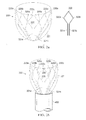
- FIG. 1 depicts a frontal view of an embodiment of the present invention.
- FIGS. 2 a and 2 b depict a schematic diagram of the elements of the self-expanding wire framework.
- FIGS. 3 a -3 e depicts the present invention at successive amounts of deployment about a plastic mock heart.
- FIGS. 4 a -4 d depicts a side view of an embodiment of the present invention showing a single articulated wire loop being drawn into the deployment tube.
- FIGS. 5 a -5 d depicts a frontal view of an embodiment of the present invention showing a single articulated wire loop being drawn into the deployment tube.
- FIGS. 6 a -6 c depicts other embodiments of the present invention showing different designs of midway bends in the articulate wire loop.
- FIGS. 7 a -7 d depicts a side view of an embodiment of the present invention showing a single articulated wire loop with rounded midway bends being drawn into the deployment tube.
- FIGS. 8 a -8 d depicts a side view of an embodiment of the present invention showing a single articulated wire loop with dual midway bends being drawn into the deployment tube.
- FIG. 9 is an image of a set of adjacent articulated wire loops.
- FIG. 10 is an image of the self-expanding wire framework.
- FIG. 11 is an image of a first set of adjacent articulated wire loops and a partially overlapping second set of adjacent articulated wire loops.
- FIGS. 12A and 12B are an image of a first set of adjacent articulated wire loops and a partially overlapping second set of adjacent articulated wire loops showing the relationship between the loops.
- FIG. 13 is an image of one embodiment of the device of the present invention.
- the present invention is directed to a minimally invasive implantation apparatus and method and is adapted to save the lives of CHF patients and dramatically shorten their hospital stays.
- a deployed device such as a cardiac compression device, in accordance with the present invention, could have restored cardiac function in as little as three weeks, allowing a shorter hospital stay and increased quality of life.
- the present invention permits at least a deployable device to be implanted quickly using a minimally invasive incision without the need for any assisting devices or guidewires. This allows patients to recover within a shorter period, resulting in a shorter hospital stays and less of a chance for infection.
- polymer or “polymer film” is use to denote a polymeric composition that is biocompatible.
- suitable, biocompatible, biostable, implantable materials include but are not limited to polyetherurethane, polycarbonateurethane, silicone, polysiloxaneurethane, hydrogenated polystyrene-butadiene copolymer, ethylene-propylene and dicyclopentadiene terpolymer, and/or hydrogenated poly(styrene-butadiene) copolymer, poly(tetramethylene-ether glycol) urethanes, poly(hexamethylenecarbonate-ethylenecarbonate glycol) urethanes elastomeric polyurethane, latex, polyetherurethane, polycarbonateurethane, silicone, polysiloxaneurethane, hydrogenated polystyrene-butadiene copolymer, ethylene-propylene and dicyclopentadiene terpolymer
- the present invention may be reinforced with filaments, made of a biocompatible, biostable, implantable polyamide, polyimide, polyester, polypropylene, polyurethane etc.
- the device may be made from different materials in different regions of the device.
- the present invention can be broadly viewed as a device comprising a deployment tube having an inner surface and an outer surface, and a self-expanding wire framework slidable along the inner surface.
- embodiment 100 of the present invention comprises a deployment tube 400 with the self-expanding wire framework 200 having polymer film 221 and being partially deployed from the deployment tube 400 .
- the DCCD device (not shown) can be attached to the self-expanding wire framework 100 before being drawn into the deployment tube 400 .
- FIG. 1 shows the device 100 having a framework 200 with the polymer film 221 in contact six articulated wire loops 220 being deployed from tube 400 .
- the leading edge or top segments 300 forms a framework 200 encloses the deployed device 100 around the heart (not shown).
- the self-expanding wire framework 200 comprises multiple articulated wire loops 220 adjacent each other but not intertwined and disposed in a polymer film 221 .
- Each of the articulated wire loops 220 includes the midway bends 320 a and 320 b to create tension when the midway bends 320 a and 320 b rotate and straighten.
- the articulated wire loops 220 include strut 321 a extending from midway bends 320 a and strut 321 b extending from midway bends 320 b .
- the top segment 300 is pointed outwards or flaring, by doing so, the left and right midway bends 320 a and 320 b .
- the left and right midway bends 320 a and 320 b must become straighter or unbend forming a configuration with higher elastic energy.
- left and right midway bends 320 a and 320 b of each further rotate and straighten out this will orient the top segment 300 to straighten out from the initial flaring motion when the framework is first deployed.
- FIGS. 2 a and 2 b depict a schematic diagram of the elements of self-expanding wire framework 200 with a polymer film 221 covering.
- the self-expanding wire framework 200 is comprised of multiple articulate wire loops 220 a - e , each comprising of a left and a right midway bends 320 a and 320 b that extend as struts 321 a and 321 b to hub (not shown).
- the top segment 300 of each articulated loops 220 is bent and compressed together to fit inside the deployment tube (not shown).
- the midway bends 320 a and 320 b of each articulated loop are straightened and compressed closer together to one another.
- the unbending or straightening of midway bends 320 a and 320 b is unstable causing it to twist or rotate rather than becoming a straight line (when struts 321 a and 321 b are not fixed relative to each other).
- the left and right midway bends 320 a and 320 b of each articulated loop 220 are compressed closer together, the left and right midway bends 320 a and 320 b rotate and orient the top segment 300 out-of-plane creating a flaring motion.
- the unstable tendency of unbending makes the top segment 300 of each articulate loop 220 protrudes radially outwards away from the hoop dimension as the top segment 300 is partially deployed.
- FIG. 2 a shows a schematic diagram and the overall shape of the self-expanding wire framework 200 having adjacent articulated wire loops 220 a - e and polymer film 221 fully deployed from the deployment tube (not shown).
- the leading edge or top segment 300 forms a circular framework 200 that encloses the deployed device around the heart (not shown).
- the self-expanding wire frame 200 comprises multiple articulated wire loops 220 a - e disposed in a polymer film 221 .
- the articulated wire loops 220 a - e are adjacent each other but not intertwined.
- the polymer film 221 may be on one side (inner surface or outer surface) of the multiple articulated wire loops 220 .
- the polymer film 221 may be on both sides (inner surface and outer surface) of the multiple articulated wire loops 220 a - e forming a sandwich configuration.
- the polymer film 221 may be a single film with the multiple articulated wire loops 220 a - e disposed within the polymer film 221 .
- Each of the articulated wire loops 220 a - e includes the midway bends 320 a and 320 b as shown in the diagram to create tension when the midway bends 320 a and 320 b rotate and straighten.
- the articulated wire loops 220 a - e include strut 321 a extending from midway bends 320 a and strut 321 b extending from midway bends 320 b .
- the position of strut 321 a and 321 b are fixed relative each other so that the strut 321 a and 321 b themselves cannot rotate or turn thus forcing movement about the midway bends 320 a and 320 b .
- the left midway bend 320 a and right midway bend 320 b of each of the articulated wire loops 220 a - e results in a tension that causes the self-expanding wire framework 200 to engage in a circumferential flaring motion and end out of plane when deployed from the deployment tube (not shown).
- FIG. 2 b shows a schematic diagram and the overall shape of the self-expanding wire framework 200 having overlapping articulated wire loops 220 with the polymer film 221 covering that is fully deployed from the deployment tube (not shown).
- the leading edge or top segment 300 forms a circular framework 200 that encloses the deployed device around the heart (not shown).
- the self-expanding wire framework 200 comprises multiple articulated wire loops 220 disposed in a polymer film 221 in a partially overlapping pattern with the adjacent wire loops 220 partially overlapping (but not intertwined).
- the polymer film 221 may be on one side (inner surface or outer surface) of the multiple articulated wire loops 220 .
- the polymer film 221 may be on both sides (inner surface and outer surface) of the multiple articulated wire loops 220 forming a sandwich configuration. Alternatively, the polymer film 221 may be a single film with the multiple articulated wire loops 220 disposed with in the polymer film 221 .
- Each of the articulated wire loops 220 includes the midway bends 320 a and 320 b as shown in the diagram to create tension when the midway bends 320 a and 320 b rotate and straighten.
- the articulated wire loops include strut 321 a extending from midway bends 320 a and strut 321 b extending from midway bends 320 b .
- the position of strut 321 a and 321 b are fixed relative to each other so that the strut 321 a and 321 b cannot rotate or turn forcing movement about the midway bends 320 a and 320 b .
- the left midway bend 320 a and right midway bend 320 b of each of the articulated wire loops 220 results in a tension that causes the self-expanding wire framework 200 to engage in a circumferential flaring motion and end out of plane when deployed from the deployment tube.
- the self-expanding wire framework 200 has partially overlapping articulated wire loops 220 which are covered by polymer film 221 .
- Each articulated wire loop has a left midway bend 320 a and a right midway bend 320 b .
- the adjacent wire loop at least partially overlaps a second wire loop by placing the left midway bend of a first wire loop behind the right midway bend of the second wire loop this pattern is repeated until the desired number of the articulated wire loops are achieved.
- FIGS. 3 a -3 b depict an embodiment of the present invention at successive amounts of deployment about a plastic mock heart 2 (3D printed from a CT scan of a normal adult sheep).
- FIGS. 3 a -3 e illustrated the flaring and straightening of the framework 200 as it was deployed from the deployment tube 400 .
- the flaring motion can also be observed with just a single articulated wire loop as seen in FIGS. 4-8 .
- FIG. 3 a shows the self-expanding wire framework 200 compressed inside deployment tube 400 as it is deployed about a plastic mock heart 2 .
- FIG. 3 a shows a polymer film 221 with an articulated wire loop 220 with the top segment 300 flanked by the left and right midway bends 320 a and 320 b and include strut 321 a extending from midway bends 320 a and strut 321 b extending from midway bends 320 b as it is deployed from the deployment tube 400 .
- the articulated wire loop 220 is deployed from the deployment tube 400 such that the left and right midway bends 320 a and 320 b are within the deployment tube 400 .
- FIG. 3 b shows the initial deployment of framework 200 wherein the top segments 300 of each of the articulated wire loop 220 are beginning to engage in a circumferential flaring motion and bend out of plane as it is deployed about a plastic mock heart 2 .
- FIG. 3 b shows a polymer film 221 with an articulated wire loop 220 with the top segment 300 flanked by the left and right midway bends 320 a and 320 b and include strut 321 a extending from midway bends 320 a and strut 321 b extending from midway bends 320 b as it is deployed from the deployment tube 400 .
- the articulated wire loop 220 is deployed from the deployment tube 400 such that the left and right midway bends 320 a and 320 b are extending from the deployment tube 400 .
- FIG. 3 c illustrates the framework deployed to the midway bends 320 which are bent outwards flaring the top segment 300 out.
- FIG. 3 c shows a polymer film 221 with an articulated wire loop 220 with the top segment 300 flanked by the left and right midway bends 320 a and 320 b and include strut 321 a extending from midway bends 320 a and strut 321 b extending from midway bends 320 b as it is deployed from the deployment tube 400 .
- the articulated wire loop 220 is deployed from the deployment tube 400 such that the left and right midway bends 320 a and 320 b and the polymer film 221 are extending past the deployment tube 400 .
- FIG. 3 d shows the struts 321 a and 321 b connected to midway bends 320 a and 320 b which straighten out to configure to a form of higher elastic energy.
- the framework 200 is deployed pass the midway bends 320 , about a plastic mock heart 2 .
- FIG. 3 d shows a polymer film 221 with an articulated wire loop 220 with the top segment 300 flanked by the left and right midway bends 320 a and 320 b and include strut 321 a extending from midway bends 320 a and strut 321 b extending from midway bends 320 b as it is deployed from the deployment tube 400 .
- the articulated wire loop 220 is deployed from the deployment tube 400 such that the left and right midway bends 320 a and 320 b are extending past the deployment tube 400 . As the midway bends 320 a and 320 b are straightened out, the top segment 300 of each articulated wire loop 220 are reoriented inwards from the initial flared position. The reorientation of the articulated wire loops 220 allows the top segment 300 of each wire loop 220 and the polymer film 221 to make contact with the outer circumference of the heart 2 .
- FIG. 3 e illustrates the full deployment of the framework 200 as each articulated wire loop 220 is further expanded to encircle a larger portion of the heart 2 .
- the framework 200 is deployed pass the midway bends 320 , about a plastic mock heart 2 .
- FIG. 3 e shows a polymer film 221 with an articulated wire loop 220 with the top segment 300 flanked by the left and right midway bends 320 a and 320 b and include strut 321 a extending from midway bends 320 a and strut 321 b extending from midway bends 320 b as it is deployed from the deployment tube 400 .
- the articulated wire loop 220 is deployed from the deployment tube 400 such that the left and right midway bends 320 a and 320 b and the polymer film 221 are extending past the deployment tube 400 to encircle a larger portion of the heart 2 .
- the self-expanding wire framework device of the present invention includes multiple articulated wire loops with a polymer film connected thereto.
- the number of articulated wire loops used is at the discretion of the manufacturer and depends on the size of the deployable device. As little as 2 articulated wire loops can be used, but the number can increase to 3, 4, 5, 6, 7, 8, 9, 10, 11, 12, or more articulated wire loops linked.
- Each of the articulated wire loops include struts that connect the midway bends to the hub (not shown). The struts are fixed in position relative to the midway bends to induce flaring when extended from the deployment tube. The fixation location can vary with the deployment of the framework as tension between the articulate wire loops may move the linkage. However, the struts between the loops may also be fixated to limit the maximum expansion size of the wire framework.
- FIGS. 4 a -4 d depicts a side view of an embodiment of the present invention showing a single articulated wire loop 220 being drawn into the deployment tube 400 .
- the articulated loop 220 is beginning to be drawn into the deployment tube 400 which compresses the left and right midway bends 320 a and 320 b together to allow top segments 300 to move inwardly.
- the articulated loop 220 is beginning to be drawn into the deployment tube 400 which compresses the left and right midway bends 320 a and 320 b together.
- flaring of the top segment 300 is evident between FIGS. 4 a and 4 b .
- FIG. 4 c shows an oriented wire loop 220 with the left and right midway bends 320 a and 320 b bent and flaring the top segment 300 outwardly.
- FIG. 4 d shows the articulated wire loop 220 drawn into the deployment tube 400 to the left and right midway bends 320 a and 320 b .
- Each of the articulated wire loops 220 will have a pair of struts extending into the deployment tube 400 that may or may not be compressed. The present invention would still function if the loop ends were crossed or parallel within the deployment tube 400 .
- FIGS. 5 a -5 d depicts a frontal view of the single articulated wire loop 220 being drawn into the deployment tube 400 and correspond with FIGS. 4 a -4 d respectively.
- the bending and flaring of the midway bends 320 a and 320 b in the deployment tube 400 cannot be seen in the frontal view, but the compression of the midway bends 320 a and 320 b together is clear.
- FIGS. 5 b and 5 c show the reorientation of the wire loop 220 as the midway bends 320 a and 320 b are compressed into the deployment tube 400 .
- 5 d shows that after the midway bends 320 a and 320 b are reached, the rest of the wire loop up to the top segment 300 are compressed together to be drawn into the deployment tube 400 .
- this compressed form is the configuration the loop 220 will be deployed at which leads to the initial flaring out position shown in FIG. 4 d when the wire loop 220 is first deployed.
- the apparatus is adapted to permit deployment of a deployable device, such as a heart assist or cardiac compression device; the self-expanding wire framework equipped with the deployable device being collapsible to fit inside the deployment tube to be positioned near the heart, and then deployed to advance around a heart without the need of any guidewires; the apparatus comprising a minimal number of components—including a self-expanding wire framework adapted to engage a deployable device, expand the deployable device and guide the deployable device during deployment; and the self-expanding wire framework and deployment tube being separated or integrated into a single unit.
- a deployable device such as a heart assist or cardiac compression device
- the self-expanding wire framework equipped with the deployable device being collapsible to fit inside the deployment tube to be positioned near the heart, and then deployed to advance around a heart without the need of any guidewires
- the apparatus comprising a minimal number of components—including a self-expanding wire framework adapted to engage a deployable device, expand
- the wire used for constructing the self-expanding wire frame will need to be an appropriate wire stiffness to achieve desired expansion and flaring out but not cause inversion of the wireframe during deployment.
- the use of quadrilateral or non-round wires will allow orienting the wire cross section such that it naturally causes the flaring motion upon deployment from the deployment tube.
- An example would be a rectangular wire with the long length of the cross-section oriented along the periphery of the device, around the heart.
- the self-expanding wire fragment should be in a flaring position with the top segment 300 of each of the articulated wire loops out of plane.
- the midway bends of the articulated wire loop can be made more rounded to allow for gradual flaring as the framework is deployed.
- the midway bends can also comprise multiple bends (two bends instead of one midway bend).
- Other embodiments can include 3, 4, 5 or more bends depending on the preference of the manufacturer.
- the diamond shape of the articulated wire loop is not the only possible element design. Various other shapes and designs are possible as long as there is a bending top segment 300 and midway bends in a left segment and a right segment that bend outward when the wire loop is collapsed and packed into the deployment tube.
- FIG. 6 a shows a schematic of an embodiment of articulated wire loop 240 with the top segment 300 flanked by the left and right midway bends 320 a and 320 b which are more rounded and include strut 321 a extending from midway bends 320 a and strut 321 b extending from midway bends 320 b into the deployment tube (not shown).
- Another embodiment includes articulated wire loop 260 with the top segment 300 flanked by the left and right midway bends 320 a and 320 b which are more flat and include strut 321 a extending from midway bends 320 a and strut 321 b extending from midway bends 320 b into the deployment tube (not shown).
- FIG. 6 b shows an articulated wire loop 240 with the top segment 300 flanked by the left and right midway bends 320 a and 320 b which are more rounded and include strut 321 a extending from midway bends 320 a and strut 321 b extending from midway bends 320 b into the deployment tube 400 .
- FIG. 6 c shows an articulated wire loop 260 with the top segment 300 flanked by the left and right midway bends 320 a and 320 b which are more flat and include strut 321 a extending from midway bends 320 a and strut 321 b extending from midway bends 320 b into the deployment tube 400 .
- FIGS. 7 a -7 d illustrate a side view of articulated wire loop 240 being drawn into deployment tube 400 .
- FIG. 7 a shows an articulated wire loop 240 with the top segment 300 flanked by the left and right midway bends 320 a and 320 b which are more rounded and include strut 321 a extending from midway bends 320 a and strut 321 b extending from midway bends 320 b drawn into the deployment tube 400 .
- FIG. 7 b shows an articulated wire loop 240 with the top segment 300 flanked by the left and right midway bends 320 a and 320 b which are more rounded and include strut 321 a extending from midway bends 320 a and strut 321 b extending from midway bends 320 b drawn into the deployment tube 400 .
- FIG. 7 c shows an articulated wire loop 240 with the top segment 300 flanked by the left and right midway bends 320 a and 320 b which are more rounded and include strut 321 a extending from midway bends 320 a and strut 321 b extending from midway bends 320 b drawn into the deployment tube 400 .
- the articulated wire loop 240 is drawn into the deployment tube 400 to the left and right midway bends 320 a and 320 b.
- FIG. 7 d shows an articulated wire loop 240 with the top segment 300 flanked by the left and right midway bends 320 a and 320 b which are more rounded and include strut 321 a extending from midway bends 320 a and strut 321 b extending from midway bends 320 b drawn into the deployment tube 400 .
- the articulated wire loop 240 is drawn into the deployment tube 400 such that the left and right midway bends 320 a and 320 b are within the deployment tube 400 .
- FIG. 8 a shows an articulated wire loop 260 with the top segment 300 flanked by the left and right midway bends 320 a and 320 b which are more rounded and include strut 321 a extending from midway bends 320 a and strut 321 b extending from midway bends 320 b drawn into the deployment tube 400 .
- FIG. 8 b shows an articulated wire loop 260 with the top segment 300 flanked by the left and right midway bends 320 a and 320 b which are more rounded and include strut 321 a extending from midway bends 320 a and strut 321 b extending from midway bends 320 b drawn into the deployment tube 400 .
- FIG. 8 c shows an articulated wire loop 260 with the top segment 300 flanked by the left and right midway bends 320 a and 320 b which are more rounded and include strut 321 a extending from midway bends 320 a and strut 321 b extending from midway bends 320 b drawn into the deployment tube 400 .
- the articulated wire loop 240 is drawn into the deployment tube 400 to the left and right midway bends 320 a and 320 b.
- FIG. 8 d shows an articulated wire loop 260 with the top segment 300 flanked by the left and right midway bends 320 a and 320 b which are more rounded and include strut 321 a extending from midway bends 320 a and strut 321 b extending from midway bends 320 b drawn into the deployment tube 400 .
- the articulated wire loop 240 is drawn into the deployment tube 400 such that the left and right midway bends 320 a and 320 b are within the deployment tube 400 .
- FIG. 9 is an image of a set of adjacent articulated wire loops.
- FIG. 9 shows an articulated wire loop 260 with the top segment 300 flanked by the left and right midway bends 320 a and 320 b which are more rounded and include strut 321 a extending from midway bends 320 a and strut 321 b extending from midway bends 320 b with a crimp connector 420 connecting struts 321 a and 321 b from adjacent loops 300 .
- FIG. 10 is an image of the self-expanding wire framework.
- FIG. 10 shows an articulated wire loop 260 with the top segment 300 flanked by the left and right midway bends 320 a and 320 b which are more rounded and include strut 321 a extending from midway bends 320 a and strut 321 b extending from midway bends 320 b with a crimp connector 420 connecting struts 321 a and 321 b from adjacent loops 300 to form a circular self-expanding wire framework.
- FIG. 11 is an image of a first set of adjacent articulated wire loops and a partially overlapping second set of adjacent articulated wire loops.
- FIG. 11 shows an articulated wire loop with the top segment flanked by the left and right midway bends and which are more rounded and include strut extending from midway bends and strut extending from midway bends with a crimp connector connecting struts and from adjacent loops.
- FIGS. 12A and 12B are images of a first set of adjacent articulated wire loops and a partially overlapping second set of adjacent articulated wire loops showing the relationship between the loops.
- FIGS. 12A and 12B each show an articulated wire loop 260 with the top segment 300 flanked by the left and right midway bends 320 a and 320 b which are more rounded and include strut 321 a extending from midway bends 320 a and strut 321 b extending from midway bends 320 b with a crimp connector 420 connecting struts 321 a and 321 b from adjacent loops 300 .
- FIG. 13 is an image of one embodiment of the device of the present invention.
- FIG. 13 shows an articulated wire loop with the top segment flanked by the left and right midway bends and which are more rounded and include strut extending from midway bends and strut extending from midway bends with a crimp connector connecting struts and from adjacent loops.
- FIGS. 3 a -3 e Various attachment means may also be utilized between a polymer film chamber and the wire frame so as not to impede on desired bending.
- One example as shown in FIGS. 3 a -3 e is to strap the wires between layers of plastic.
- Another embodiment would be to allow wire movement and rotation within the polymer film attachment points.
- the words “comprising” (and any form of comprising, such as “comprise” and “comprises”), “having” (and any form of having, such as “have” and “has”), “including” (and any form of including, such as “includes” and “include”) or “containing” (and any form of containing, such as “contains” and “contain”) are inclusive or open-ended and do not exclude additional, unrecited elements or method steps.
- A, B, C, or combinations thereof refers to all permutations and combinations of the listed items preceding the term.
- “A, B, C, or combinations thereof” is intended to include at least one of: A, B, C, AB, AC, BC, or ABC, and if order is important in a particular context, also BA, CA, CB, CBA, BCA, ACB, BAC, or CAB.
- expressly included are combinations that contain repeats of one or more item or term, such as BB, AAA, AB, BBC, AAABCCCC, CBBAAA, CABABB, and so forth.
- BB BB
- AAA AAA
- AB BBC
- AAABCCCCCC CBBAAA
- CABABB CABABB
- compositions and/or methods disclosed and claimed herein can be made and executed without undue experimentation in light of the present disclosure. While the compositions and methods of this invention have been described in terms of preferred embodiments, it will be apparent to those of skill in the art that variations may be applied to the compositions and/or methods and in the steps or in the sequence of steps of the method described herein without departing from the concept, spirit and scope of the invention. All such similar substitutes and modifications apparent to those skilled in the art are deemed to be within the spirit, scope and concept of the invention as defined by the appended claims.
Landscapes
- Health & Medical Sciences (AREA)
- Cardiology (AREA)
- Oral & Maxillofacial Surgery (AREA)
- Transplantation (AREA)
- Engineering & Computer Science (AREA)
- Biomedical Technology (AREA)
- Heart & Thoracic Surgery (AREA)
- Vascular Medicine (AREA)
- Life Sciences & Earth Sciences (AREA)
- Animal Behavior & Ethology (AREA)
- General Health & Medical Sciences (AREA)
- Public Health (AREA)
- Veterinary Medicine (AREA)
- Prostheses (AREA)
Abstract
Description
Claims (17)
Priority Applications (1)
| Application Number | Priority Date | Filing Date | Title |
|---|---|---|---|
| US15/811,226 US10463496B2 (en) | 2015-07-15 | 2017-11-13 | Self-expanding heart assist device |
Applications Claiming Priority (3)
| Application Number | Priority Date | Filing Date | Title |
|---|---|---|---|
| US201562192725P | 2015-07-15 | 2015-07-15 | |
| US15/211,662 US9833318B2 (en) | 2015-07-15 | 2016-07-15 | Self-expanding heart assist device |
| US15/811,226 US10463496B2 (en) | 2015-07-15 | 2017-11-13 | Self-expanding heart assist device |
Related Parent Applications (1)
| Application Number | Title | Priority Date | Filing Date |
|---|---|---|---|
| US15/211,662 Continuation-In-Part US9833318B2 (en) | 2015-07-15 | 2016-07-15 | Self-expanding heart assist device |
Publications (2)
| Publication Number | Publication Date |
|---|---|
| US20180193147A1 US20180193147A1 (en) | 2018-07-12 |
| US10463496B2 true US10463496B2 (en) | 2019-11-05 |
Family
ID=62782585
Family Applications (1)
| Application Number | Title | Priority Date | Filing Date |
|---|---|---|---|
| US15/811,226 Active US10463496B2 (en) | 2015-07-15 | 2017-11-13 | Self-expanding heart assist device |
Country Status (1)
| Country | Link |
|---|---|
| US (1) | US10463496B2 (en) |
Cited By (7)
| Publication number | Priority date | Publication date | Assignee | Title |
|---|---|---|---|---|
| US11376417B2 (en) | 2018-06-06 | 2022-07-05 | The Regents Of The University Of California | Whole heart assist device |
| US11896812B1 (en) | 2023-01-27 | 2024-02-13 | Lifebridge Technologies Llc | Versatile modular heart pump for non-blood contacting ventricular function augmentation |
| US12115363B1 (en) | 2023-08-10 | 2024-10-15 | Lifebridge Technologies Llc | System and method for introducing a construct either on or around the surface of the heart |
| US12440338B2 (en) | 2020-10-01 | 2025-10-14 | Lifebridge Technologies Llc | Minimally invasive heart pump with modular adjustable construct insertion |
| US12478475B2 (en) | 2020-10-01 | 2025-11-25 | Lifebridge Technologies Llc | Single tube pressurization system for a heart pump |
| US12478773B2 (en) | 2020-10-01 | 2025-11-25 | Lifebridge Technologies Llc | Dynamic drive system for cardiac systolic and diastolic assist |
| US12616827B2 (en) | 2023-11-14 | 2026-05-05 | Lifebridge Technologies Llc | System and method for assisting the heart in pumping blood |
Families Citing this family (4)
| Publication number | Priority date | Publication date | Assignee | Title |
|---|---|---|---|---|
| EP3845255B1 (en) * | 2018-08-30 | 2023-03-15 | Cyberdyne Inc. | Cardiac pumping assistance device |
| EP3914309A1 (en) | 2019-01-24 | 2021-12-01 | Artract Medical GmbH | Medical chamber system, introduction system and kit |
| EP4514273A4 (en) * | 2022-04-28 | 2026-03-18 | Corinnova Incorporated | METHOD AND DEVICE FOR OPTIMIZING THE CHARGE OF A CARDIAC SUPPORT DEVICE |
| WO2025136892A1 (en) * | 2023-12-20 | 2025-06-26 | Edwards Lifesciences Corporation | Pericardial implants |
-
2017
- 2017-11-13 US US15/811,226 patent/US10463496B2/en active Active
Cited By (8)
| Publication number | Priority date | Publication date | Assignee | Title |
|---|---|---|---|---|
| US11376417B2 (en) | 2018-06-06 | 2022-07-05 | The Regents Of The University Of California | Whole heart assist device |
| US12440338B2 (en) | 2020-10-01 | 2025-10-14 | Lifebridge Technologies Llc | Minimally invasive heart pump with modular adjustable construct insertion |
| US12478475B2 (en) | 2020-10-01 | 2025-11-25 | Lifebridge Technologies Llc | Single tube pressurization system for a heart pump |
| US12478773B2 (en) | 2020-10-01 | 2025-11-25 | Lifebridge Technologies Llc | Dynamic drive system for cardiac systolic and diastolic assist |
| US11896812B1 (en) | 2023-01-27 | 2024-02-13 | Lifebridge Technologies Llc | Versatile modular heart pump for non-blood contacting ventricular function augmentation |
| US12115363B1 (en) | 2023-08-10 | 2024-10-15 | Lifebridge Technologies Llc | System and method for introducing a construct either on or around the surface of the heart |
| US12377259B2 (en) | 2023-08-10 | 2025-08-05 | Lifebridge Technologies Llc | System and method for introducing a construct either on or around the surface of the heart |
| US12616827B2 (en) | 2023-11-14 | 2026-05-05 | Lifebridge Technologies Llc | System and method for assisting the heart in pumping blood |
Also Published As
| Publication number | Publication date |
|---|---|
| US20180193147A1 (en) | 2018-07-12 |
Similar Documents
| Publication | Publication Date | Title |
|---|---|---|
| US10463496B2 (en) | Self-expanding heart assist device | |
| US11510780B2 (en) | System and method for cardiac valve repair and replacement | |
| US9833318B2 (en) | Self-expanding heart assist device | |
| CN111031967B (en) | Prosthetic heart valve with tether connection features | |
| US11589985B2 (en) | Apparatus and methods for transfemoral delivery of prosthetic mitral valve | |
| ES3033931T3 (en) | Delivery device for balloon expandable endoprosthesis | |
| US10631839B2 (en) | Implantable device | |
| CN103237524B (en) | artificial heart valve | |
| US12376956B2 (en) | Percutaneous shunt devices and related methods | |
| CN109640836A (en) | Tissue anchor with the flexible tip for being inserted into cavum pericardiale | |
| US20220296865A1 (en) | Percutaneous potts shunt devices and related methods | |
| CN112754732B (en) | Interventional artificial heart valve and medical device | |
| JP2018520783A5 (en) | ||
| US20220054259A1 (en) | Flexible Anchor For Prosthetic Heart Valve | |
| KR102754881B1 (en) | Implantable artificial heart valves and medical devices | |
| EP3322380B1 (en) | Self-expanding heart assist device | |
| US20220387173A1 (en) | Expandable Anchor For Prosthetic Mitral Valve | |
| US20250325268A1 (en) | Percutaneous shunt devices and methods |
Legal Events
| Date | Code | Title | Description |
|---|---|---|---|
| FEPP | Fee payment procedure |
Free format text: ENTITY STATUS SET TO UNDISCOUNTED (ORIGINAL EVENT CODE: BIG.); ENTITY STATUS OF PATENT OWNER: SMALL ENTITY |
|
| FEPP | Fee payment procedure |
Free format text: ENTITY STATUS SET TO SMALL (ORIGINAL EVENT CODE: SMAL); ENTITY STATUS OF PATENT OWNER: SMALL ENTITY |
|
| AS | Assignment |
Owner name: THE TEXAS A&M UNIVERISTY SYSTEM, TEXAS Free format text: ASSIGNMENT OF ASSIGNORS INTEREST;ASSIGNOR:CRISCIONE, JOHN C.;REEL/FRAME:045371/0063 Effective date: 20180327 Owner name: CORINNOVA INCORPORATED, TEXAS Free format text: ASSIGNMENT OF ASSIGNORS INTEREST;ASSIGNORS:LESCHINSKY, BORIS;BOLCH, CHRISTINA M.;SIGNING DATES FROM 20171128 TO 20180326;REEL/FRAME:045371/0195 |
|
| STPP | Information on status: patent application and granting procedure in general |
Free format text: FINAL REJECTION MAILED |
|
| STPP | Information on status: patent application and granting procedure in general |
Free format text: DOCKETED NEW CASE - READY FOR EXAMINATION |
|
| STPP | Information on status: patent application and granting procedure in general |
Free format text: NOTICE OF ALLOWANCE MAILED -- APPLICATION RECEIVED IN OFFICE OF PUBLICATIONS |
|
| STPP | Information on status: patent application and granting procedure in general |
Free format text: PUBLICATIONS -- ISSUE FEE PAYMENT VERIFIED |
|
| STCF | Information on status: patent grant |
Free format text: PATENTED CASE |
|
| MAFP | Maintenance fee payment |
Free format text: PAYMENT OF MAINTENANCE FEE, 4TH YR, SMALL ENTITY (ORIGINAL EVENT CODE: M2551); ENTITY STATUS OF PATENT OWNER: SMALL ENTITY Year of fee payment: 4 |