US10455122B2 - Profile adjustment method, profile adjustment apparatus, and profile adjustment system - Google Patents
Profile adjustment method, profile adjustment apparatus, and profile adjustment system Download PDFInfo
- Publication number
- US10455122B2 US10455122B2 US16/143,618 US201816143618A US10455122B2 US 10455122 B2 US10455122 B2 US 10455122B2 US 201816143618 A US201816143618 A US 201816143618A US 10455122 B2 US10455122 B2 US 10455122B2
- Authority
- US
- United States
- Prior art keywords
- values
- adjustment
- profile
- color
- target
- Prior art date
- Legal status (The legal status is an assumption and is not a legal conclusion. Google has not performed a legal analysis and makes no representation as to the accuracy of the status listed.)
- Active
Links
- 238000000034 method Methods 0.000 title claims abstract description 187
- 238000005457 optimization Methods 0.000 claims abstract description 70
- 238000006243 chemical reaction Methods 0.000 claims description 115
- 230000001419 dependent effect Effects 0.000 claims description 35
- 239000013598 vector Substances 0.000 claims description 23
- 238000007639 printing Methods 0.000 claims description 22
- 239000003086 colorant Substances 0.000 description 72
- 230000006870 function Effects 0.000 description 53
- 239000000976 ink Substances 0.000 description 36
- 238000010586 diagram Methods 0.000 description 16
- 238000012545 processing Methods 0.000 description 14
- 239000000463 material Substances 0.000 description 12
- 239000000758 substrate Substances 0.000 description 8
- 238000004364 calculation method Methods 0.000 description 7
- 238000004891 communication Methods 0.000 description 7
- 238000012937 correction Methods 0.000 description 4
- 230000000694 effects Effects 0.000 description 4
- 238000011156 evaluation Methods 0.000 description 4
- 230000002349 favourable effect Effects 0.000 description 3
- 238000005259 measurement Methods 0.000 description 3
- 238000002939 conjugate gradient method Methods 0.000 description 2
- 239000000470 constituent Substances 0.000 description 2
- 230000007423 decrease Effects 0.000 description 2
- 238000013507 mapping Methods 0.000 description 2
- 239000000203 mixture Substances 0.000 description 2
- 238000007645 offset printing Methods 0.000 description 2
- 238000009877 rendering Methods 0.000 description 2
- 239000004065 semiconductor Substances 0.000 description 2
- 239000000654 additive Substances 0.000 description 1
- 230000000996 additive effect Effects 0.000 description 1
- 238000007599 discharging Methods 0.000 description 1
- 238000007647 flexography Methods 0.000 description 1
- 238000007646 gravure printing Methods 0.000 description 1
- 238000005286 illumination Methods 0.000 description 1
- 239000004973 liquid crystal related substance Substances 0.000 description 1
- 238000004088 simulation Methods 0.000 description 1
Images


Classifications
-
- H—ELECTRICITY
- H04—ELECTRIC COMMUNICATION TECHNIQUE
- H04N—PICTORIAL COMMUNICATION, e.g. TELEVISION
- H04N1/00—Scanning, transmission or reproduction of documents or the like, e.g. facsimile transmission; Details thereof
- H04N1/00002—Diagnosis, testing or measuring; Detecting, analysing or monitoring not otherwise provided for
- H04N1/00007—Diagnosis, testing or measuring; Detecting, analysing or monitoring not otherwise provided for relating to particular apparatus or devices
- H04N1/00023—Colour systems
-
- H—ELECTRICITY
- H04—ELECTRIC COMMUNICATION TECHNIQUE
- H04N—PICTORIAL COMMUNICATION, e.g. TELEVISION
- H04N1/00—Scanning, transmission or reproduction of documents or the like, e.g. facsimile transmission; Details thereof
- H04N1/46—Colour picture communication systems
- H04N1/56—Processing of colour picture signals
- H04N1/60—Colour correction or control
- H04N1/6002—Corrections within particular colour systems
- H04N1/6008—Corrections within particular colour systems with primary colour signals, e.g. RGB or CMY(K)
-
- G—PHYSICS
- G01—MEASURING; TESTING
- G01J—MEASUREMENT OF INTENSITY, VELOCITY, SPECTRAL CONTENT, POLARISATION, PHASE OR PULSE CHARACTERISTICS OF INFRARED, VISIBLE OR ULTRAVIOLET LIGHT; COLORIMETRY; RADIATION PYROMETRY
- G01J3/00—Spectrometry; Spectrophotometry; Monochromators; Measuring colours
- G01J3/46—Measurement of colour; Colour measuring devices, e.g. colorimeters
- G01J3/462—Computing operations in or between colour spaces; Colour management systems
-
- G—PHYSICS
- G01—MEASURING; TESTING
- G01J—MEASUREMENT OF INTENSITY, VELOCITY, SPECTRAL CONTENT, POLARISATION, PHASE OR PULSE CHARACTERISTICS OF INFRARED, VISIBLE OR ULTRAVIOLET LIGHT; COLORIMETRY; RADIATION PYROMETRY
- G01J3/00—Spectrometry; Spectrophotometry; Monochromators; Measuring colours
- G01J3/46—Measurement of colour; Colour measuring devices, e.g. colorimeters
- G01J3/463—Colour matching
-
- G—PHYSICS
- G01—MEASURING; TESTING
- G01J—MEASUREMENT OF INTENSITY, VELOCITY, SPECTRAL CONTENT, POLARISATION, PHASE OR PULSE CHARACTERISTICS OF INFRARED, VISIBLE OR ULTRAVIOLET LIGHT; COLORIMETRY; RADIATION PYROMETRY
- G01J3/00—Spectrometry; Spectrophotometry; Monochromators; Measuring colours
- G01J3/46—Measurement of colour; Colour measuring devices, e.g. colorimeters
- G01J3/52—Measurement of colour; Colour measuring devices, e.g. colorimeters using colour charts
-
- H—ELECTRICITY
- H04—ELECTRIC COMMUNICATION TECHNIQUE
- H04N—PICTORIAL COMMUNICATION, e.g. TELEVISION
- H04N1/00—Scanning, transmission or reproduction of documents or the like, e.g. facsimile transmission; Details thereof
- H04N1/00127—Connection or combination of a still picture apparatus with another apparatus, e.g. for storage, processing or transmission of still picture signals or of information associated with a still picture
- H04N1/00204—Connection or combination of a still picture apparatus with another apparatus, e.g. for storage, processing or transmission of still picture signals or of information associated with a still picture with a digital computer or a digital computer system, e.g. an internet server
- H04N1/00236—Connection or combination of a still picture apparatus with another apparatus, e.g. for storage, processing or transmission of still picture signals or of information associated with a still picture with a digital computer or a digital computer system, e.g. an internet server using an image reading or reproducing device, e.g. a facsimile reader or printer, as a local input to or local output from a computer
-
- H—ELECTRICITY
- H04—ELECTRIC COMMUNICATION TECHNIQUE
- H04N—PICTORIAL COMMUNICATION, e.g. TELEVISION
- H04N1/00—Scanning, transmission or reproduction of documents or the like, e.g. facsimile transmission; Details thereof
- H04N1/40—Picture signal circuits
- H04N1/40025—Circuits exciting or modulating particular heads for reproducing continuous tone value scales
-
- H—ELECTRICITY
- H04—ELECTRIC COMMUNICATION TECHNIQUE
- H04N—PICTORIAL COMMUNICATION, e.g. TELEVISION
- H04N1/00—Scanning, transmission or reproduction of documents or the like, e.g. facsimile transmission; Details thereof
- H04N1/40—Picture signal circuits
- H04N1/40087—Multi-toning, i.e. converting a continuous-tone signal for reproduction with more than two discrete brightnesses or optical densities, e.g. dots of grey and black inks on white paper
-
- H—ELECTRICITY
- H04—ELECTRIC COMMUNICATION TECHNIQUE
- H04N—PICTORIAL COMMUNICATION, e.g. TELEVISION
- H04N1/00—Scanning, transmission or reproduction of documents or the like, e.g. facsimile transmission; Details thereof
- H04N1/46—Colour picture communication systems
- H04N1/50—Picture reproducers
-
- H—ELECTRICITY
- H04—ELECTRIC COMMUNICATION TECHNIQUE
- H04N—PICTORIAL COMMUNICATION, e.g. TELEVISION
- H04N1/00—Scanning, transmission or reproduction of documents or the like, e.g. facsimile transmission; Details thereof
- H04N1/46—Colour picture communication systems
- H04N1/56—Processing of colour picture signals
- H04N1/60—Colour correction or control
- H04N1/603—Colour correction or control controlled by characteristics of the picture signal generator or the picture reproducer
- H04N1/6033—Colour correction or control controlled by characteristics of the picture signal generator or the picture reproducer using test pattern analysis
-
- H—ELECTRICITY
- H04—ELECTRIC COMMUNICATION TECHNIQUE
- H04N—PICTORIAL COMMUNICATION, e.g. TELEVISION
- H04N1/00—Scanning, transmission or reproduction of documents or the like, e.g. facsimile transmission; Details thereof
- H04N1/46—Colour picture communication systems
- H04N1/64—Systems for the transmission or the storage of the colour picture signal; Details therefor, e.g. coding or decoding means therefor
- H04N1/646—Transmitting or storing colour television type signals, e.g. PAL, Lab; Their conversion into additive or subtractive colour signals or vice versa therefor
Definitions
- the invention relates to a technique for adjusting a profile used in conversion of coordinate values in a color space.
- the ICC profile is data expressing a correspondence relationship between device-dependent colors of a color device such as a printing press (for example, an offset printer) or an ink jet printer, and device-independent colors.
- the device-dependent colors of the printing press, the ink jet printer, and the like are expressed as coordinate values in a device-dependent color space, for example, as CMYK values expressing usage amounts of C (cyan), M (magenta), Y (yellow), and K (black).
- the device-independent colors are expressed as, for example, color values in the International Commission on Illumination (CIE) L*a*b* color space (abbreviated as Lab values, omitting the “*”), color values in a CIE XYZ color space, and the like, which are device-independent color spaces.
- CIE International Commission on Illumination
- the ICC profile of the printing press is assumed as an input profile and the ICC profile of the ink jet printer is assumed as an output profile.
- the color values can be converted into CMYK values of the ink jet printer (called CMYK p values) in accordance with the output profile.
- CMYK p values CMYK values of the ink jet printer
- the ink jet printer can reproduce colors close to the colors of the printing press.
- spot color adjustment is carried out, where an adjustment point expressing a spot color to be adjusted is designated, an adjustment target of the adjustment point is designated, and the ICC profile is modified based on the adjustment target.
- a colorimetric value (PCS value) before adjustment can be obtained.
- PCS value colorimetric value
- a target colorimetric value can be obtained. In this case, it is conceivable to feed back the adjustment target into the ICC profile using coordinates in PCS as a reference.
- JP-A-2005-348210 discloses a technique, which is not spot color adjustment, for determining correction information for correcting color output characteristics of a second color output apparatus to color output characteristics of a first color output apparatus.
- first, CMYK values of first evaluation data are converted into a plurality of pieces of second evaluation data respectively in accordance with a plurality of pieces of correction information.
- the correction information achieving the lowest difference in color output characteristics between the first color output apparatus, which performs output using the first evaluation data, and the second color output apparatus, which performs output using the second evaluation data, is then selected.
- the color of material printed by the ink jet printer (as numerical values, the colorimetric values) may not match the intended adjustment result.
- An advantage of the invention is to provide a technique capable of improving color reproduction accuracy of a profile used in conversion of coordinate values in a color space.
- the invention has as one aspect a profile adjustment method that carries out, by a computer, a process of adjusting an adjustment target profile among a plurality of profiles including an input profile expressing a correspondence relationship between first coordinate values in a first device-dependent color space and device-independent coordinate values in a profile connection space and an output profile expressing a correspondence relationship between the device-independent coordinate values and second coordinate values in a second device-dependent color space, the profile adjustment method including:
- the output profile including a first conversion table for converting the device-independent coordinate values into the second coordinate values and a second conversion table for converting the second coordinate values into the device-independent coordinate values,
- the invention has as another aspect a profile adjustment program that causes a computer to execute functions corresponding to the steps of the above-described profile adjustment method.
- the invention has as another aspect a profile adjustment apparatus including units corresponding to the steps of the above-described profile adjustment method.
- the invention has as another aspect a profile adjustment system including units corresponding to the steps of the above-described profile adjustment method.
- the above-described aspects can provide a profile adjustment method that improves the color reproduction accuracy of the profile used to convert the coordinate values in the color space.
- FIG. 1 is a block diagram schematically illustrating an example of the configuration of a profile adjustment system.
- FIG. 2 is a diagram schematically illustrating an example of a color management flow.
- FIG. 3 is a diagram schematically illustrating an example of relationships between various profiles.
- FIG. 4 is a diagram schematically illustrating an example of the structure of a profile.
- FIG. 5 is a diagram schematically illustrating an example of the structure of a second conversion table of an output profile.
- FIG. 6 is a flowchart illustrating an example of a target setting process.
- FIG. 7 is a diagram schematically illustrating an example of a user interface screen.
- FIG. 8 is a flowchart illustrating an example of an optimization process.
- FIG. 9 is a diagram schematically illustrating an example of changing initial values of adjustment color values.
- FIG. 10 is a flowchart illustrating an example of a profile adjustment process.
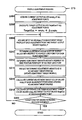
- FIGS. 11A to 11E are diagrams schematically illustrating a calculation example of current output values.
- FIG. 12 is a diagram schematically illustrating an example of setting an adjustment point.
- FIG. 13 is a diagram schematically illustrating an example of equations for calculating the current output values.
- FIGS. 14A and 14B are diagrams schematically illustrating examples of finding input values and adjustment target values of an adjustment target profile.
- FIG. 15 is a diagram schematically illustrating examples of equations for calculating the input values and the adjustment target values of the adjustment target profile.
- FIG. 16A is a diagram schematically illustrating adjustment amounts at each of grid points in a case of performing the adjustment in an output color space of an adjustment target profile
- FIG. 16B is a diagram schematically illustrating adjustment amounts at each of grid points in a case of performing the adjustment in an input color space of the adjustment target profile.
- FIG. 17A is a diagram schematically illustrating an example of determining adjustment amounts of output values with respect to nearest grid points
- FIG. 17B is a diagram schematically illustrating an example of determining adjustment amounts of output values with respect to grid points in the periphery of nearest grid points.
- FIGS. 1 to 17 the drawings in this application are drawings schematically illustrating examples. The scales in the directions indicated in the drawings may differ, and the drawings may not match with each other. Of course, elements according to this technique are not limited to specific examples indicated by reference signs.
- a profile adjustment method is a profile adjustment method in which processing for adjusting an adjustment target profile 550 is carried out by a computer (for example, a host device 100 ), and includes a target reception step ST 2 , a conversion step ST 3 , an optimization step ST 4 , and a profile adjustment step ST 5 .
- the adjustment target profile 550 is one of a plurality of profiles 500 including an input profile 610 and an output profile 620 .
- the input profile 610 expresses a correspondence relationship between first coordinate values (for example, CMYK values) in a first device-dependent color space CS 1 (for example, the CMYK color space) and device-independent coordinate values (for example, Lab values) in a profile connection space CS 3 (for example, the Lab color space).
- the output profile 620 expresses a correspondence relationship between the device-independent coordinate values (for example, Lab values) and second coordinate values (for example, cmyk values) in a second device-dependent color space CS 2 (for example, the cmyk color space).
- the output profile 620 includes a first conversion table (for example, a B2A table 621 ) for converting the device-independent coordinate values (for example, the Lab values) into the second coordinate values (for example, the cmyk values), and a second conversion table (for example, an A2B table 622 ) for converting the second coordinate values (for example, the cmyk values) into the device-independent coordinate values (for example, the Lab values).
- a first conversion table for example, a B2A table 621
- the second coordinate values for example, the cmyk values
- the second conversion table for example, an A2B table 622
- an adjustment target T 0 at an adjustment point P 0 which uses coordinates in the profile connection space CS 3 as a reference, is received.
- the device-independent coordinate values at the adjustment point P 0 for example, Lab S1
- the second coordinate values for example, cmyk p
- the second coordinate values are then converted into adjustment target PCS values (for example, Lab S2 ) as device-independent coordinate values, in accordance with the second conversion table ( 622 ).
- values obtained by adding relative values of the adjustment target T 0 using the coordinates in the profile connection space CS 3 as a reference are assumed as target PCS values (for example, Lab ST ).
- the second coordinate values at the adjustment point P 0 are assumed as adjustment target color values (cmyk p ).
- values added to the adjustment target color values (cmyk p ) for matching the adjustment target T 0 are assumed as adjustment color values (for example, ⁇ cmyk).
- an optimal solution (for example, ⁇ cmyk b ) of the adjustment color values ( ⁇ cmyk) is obtained through an optimization process including an element that brings provisional PCS values (for example, Lab S3 ), obtained by converting, according to the second conversion table ( 622 ), provisional color values (for example, cmyk pp ) obtained by adding the adjustment color values ( ⁇ cmyk) to the adjustment target color values (cmyk p ), closer to the target PCS values (Lab ST ).
- the adjustment target profile 550 is adjusted based on the optimal solution ( ⁇ cmyk b ) of the adjustment color values ( ⁇ cmyk).
- the second coordinate values (cmyk p ) obtained from the device-independent coordinate values (Lab S1 ) at the adjustment point P 0 in accordance with the first conversion table ( 621 ) of the output profile 620 express output colors of a second device (for example, a printer 200 ) having the second device-dependent color space CS 2 .
- the adjustment target PCS values (Lab S2 ) obtained from the second coordinate values (cmyk p ) in accordance with the second conversion table ( 622 ) of the output profile 620 are device-independent coordinate values expressing the output colors of the second device ( 200 ).
- Values obtained by adding the relative values ( ⁇ Lab T-p ) of the adjustment target T 0 using the coordinates in the profile connection space CS 3 as a reference to the adjustment target PCS values (Lab S2 ) are the target PCS values (Lab ST ).
- the adjustment target profile 550 is adjusted based on the optimal solution ( ⁇ cmyk b ) of the adjustment color values ( ⁇ cmyk) obtained through the optimization process, which includes an element that brings the provisional PCS values (Lab S3 ) closer to the target PCS values (Lab ST ), and thus an adjustment result with respect to the output colors of the second device ( 200 ) is closer to an intended color.
- this aspect provides a profile adjustment method that improves the color reproduction accuracy of a profile used to convert the coordinate values in a color space.
- the profile connection space includes color spaces such as the CIE Lab color space, the CIE XYZ color space, and the like.
- the first device-dependent color space includes the CMYK color space, the CMY color space, the RGB color space, and the like. Note that R stands for red, G for green, and B for blue.
- the second device-dependent color space includes the CMYK color space, the CMY color space, the RGB color space, and the like.
- the second device-dependent color space when the second device-dependent color space is the CMYK color space, the second device-dependent color space will be referred to as a cmyk color space to distinguish the color space from the CMYK color space corresponding to the first device-dependent color space.
- the plurality of profiles that can be adjustment target profiles may be two types, that is, the input profile and the output profile, or may further include a device link profile.
- the adjustment target at the adjustment point may be expressed as coordinate values in a color space, or may be expressed as a difference from current coordinate values in the color space.
- An optimization process using a quasi-Newton method, an optimization process using a Newton method, an optimization process using a conjugate gradient method, and the like can be used as the optimization process.
- Obtaining an optimal solution through an optimization process includes determining an optimal solution from among a plurality of solutions obtained by carrying out a plurality of optimization processes, and obtaining an optimal solution from a single optimization process.
- the first coordinate values (for example, CMYK in ) at the adjustment point P 0 may be converted into the device-independent coordinate values (Lab S1 ) in accordance with the input profile 610
- the device-independent coordinate values may be converted into the second coordinate values (cmyk p ) in accordance with the first conversion table ( 621 )
- the second coordinate values may be converted into the adjustment target PCS values (Lab S2 ) in accordance with the second conversion table ( 622 ).
- This aspect can provide a technique favorable when the adjustment points use coordinates in the first device-dependent color space as a reference.
- the output values of the target function decrease as the square of the color difference decreases
- the element that brings the provisional PCS values (Lab S3 ) closer to the target PCS values (Lab ST ) refers to reducing the output values of the target function.
- the square root included in the color difference does not have to be calculated, thus the optimization process can be accelerated.
- the color difference includes the color difference ⁇ E 00 expressed by the CIEDE 2000 color difference type, a color difference ⁇ E* 94 expressed by the CIE 1994 color difference type, a color difference ⁇ E* ab according to the CIE L*a*b* color system proposed in 1976 (also known as ⁇ E* 76 ), a color difference ⁇ E* uv according to the CIE L*u*v* color system, and the like.
- the optimal solution ( ⁇ cmyk b ) may be obtained through the optimization process by applying a range (for example, from 0 to 100) that the second coordinate values can take on to restriction conditions of a range of the provisional color values (cmyk pp ). Adjustment cannot be carried out when the provisional color values (cmyk pp ) exceed the range that the second coordinate values can take on, and thus this aspect provides a favorable optimization process.
- Min to Max means greater than or equal to a minimum value Min and less than or equal to a maximum value Max.
- a plurality of initial values (for example, ⁇ cmyk i ) of the adjustment color values ( ⁇ cmyk) may be used in the optimization process.
- the optimal solution ( ⁇ cmyk b ) may be obtained based on the plurality of optimal solution candidates ( ⁇ cmyk pb ).
- the profile adjustment method may further include an adjustment target profile reception step ST 1 of receiving one profile among the plurality of profiles 500 as the adjustment target profile 550 .
- the adjustment target profile 550 can be selected from the plurality of profiles 500 including the input profile 610 and the output profile 620 , and thus a technique that improves the convenience of operations for adjusting the profiles can be provided.
- a profile adjustment program PR 0 causes a computer (for example, a host device 100 ) to implement a target reception function FU 2 corresponding to the target reception step ST 2 , a conversion function FU 3 corresponding to the conversion step ST 3 , an optimization function FU 4 corresponding to the optimization step ST 4 , and a profile adjustment function FU 5 corresponding to the profile adjustment step ST 5 .
- this aspect provides a profile adjustment program that improves the color reproduction accuracy of a profile used to convert the coordinate values in a color space.
- the profile adjustment program PR 0 may cause the computer (for example, the host device 100 ) to implement an adjustment target profile reception function FU 1 corresponding to the adjustment target profile reception step ST 1 .
- a profile adjustment apparatus (for example, the host device 100 ) according to an aspect of this technique includes a target reception unit U 2 corresponding to the target reception step ST 2 , a conversion unit U 3 corresponding to the conversion step ST 3 , an optimization unit U 4 corresponding to the optimization step ST 4 , and a profile adjustment unit U 5 corresponding to the profile adjustment step ST 5 . Accordingly, this aspect provides a profile adjustment apparatus that improves the color reproduction accuracy of a profile used to convert the coordinate values in a color space.
- the profile adjustment apparatus ( 100 ) may include an adjustment target profile reception unit U 1 corresponding to the adjustment target profile reception step ST 1 .
- a profile adjustment system SY 1 includes a printing device (for example, a printer 200 ) configured to print a color chart including a patch, a colorimetric device 120 configured to measure the patch, and the units of Aspect 9. Accordingly, this aspect provides a profile adjustment system that improves the color reproduction accuracy of a profile used to convert the coordinate values in a color space.
- This profile adjustment system SY 1 may include the adjustment target profile reception unit U 1 .
- This technique can furthermore be applied in a control method of a profile adjustment apparatus, a multifunction system including a profile adjustment apparatus, a control method of a multifunction system, a control program of a profile adjustment apparatus, a control program of a multifunction system, a computer-readable medium in which is recorded a profile adjustment program, and the control program, and the like.
- the above-described apparatuses may include a plurality of separate parts.
- FIG. 1 schematically illustrates an example of the configuration of a profile adjustment system including a profile adjustment apparatus.
- the profile adjustment system SY 1 illustrated in FIG. 1 includes the host device 100 (an example of a profile adjustment apparatus), a display device 130 , the colorimetric device 120 , and the ink jet printer 200 .
- a central processing unit (CPU) 111 In the host device 100 , a central processing unit (CPU) 111 , read-only memory (ROM) 112 , random access memory (RAM) 113 , a storage device 114 , an input device 115 , a communication interface (I/F) 118 , a colorimetric device I/F 119 , and the like are connected so as to be capable of inputting/outputting information to/from each other.
- the ROM 112 , the RAM 113 , and the storage device 114 are memory, and at least the ROM 112 and the RAM 113 are semiconductor memory.
- a liquid-crystal display panel and the like can be used as
- the storage device 114 stores an operating system (OS; not illustrated), a profile adjustment program PR 0 , and the like. These may be loaded into the RAM 113 and used in the processing for adjusting the profiles 500 .
- profiles 500 collectively refers to the input profile 610 , the output profile 620 , and a device link profile 630 .
- Various types of information for example, the input profile 610 , the output profile 620 , the device link profile 630 , an adjustment history (not illustrated), and the like, are stored in at least one of the RAM 113 and the storage device 114 .
- Non-volatile semiconductor memory such as flash memory, a magnetic storage device such as a hard disk, and the like can be used as the storage device 114 .
- a pointing device, hardware keys including a keyboard, a touch panel affixed to a surface of a display panel, and the like can be used as the input device 115 .
- the communication I/F 118 is connected to a communication I/F 210 of the printer 200 , and inputs/outputs information such as print data to/from the printer 200 .
- the colorimetric device I/F 119 is connected to the colorimetric device 120 , and obtains colorimetric data, including colorimetric values, from the colorimetric device 120 .
- Universal Serial Bus (USB), a near-field wireless communication standard, and the like can be used as the standard of the I/Fs 118 , 119 , and 210 .
- the communication by the communication I/Fs 118 , 119 , and 210 may be hard-wired, may be wireless, or may be network communication over a local area network (LAN), the internet, and the like.
- LAN local area network
- the colorimetric device 120 can measure respective color patches formed on a print substrate, which is an example of a medium on which a color chart is formed, and output colorimetric values.
- the patch is also called a “color chart”.
- the colorimetric values are values expressed as a lightness L and color component coordinates a and b in the CIE Lab color space, for example.
- the host device 100 obtains the colorimetric data from the colorimetric device 120 and carries out various processes.
- the profile adjustment program PR 0 illustrated in FIG. 1 causes the host device 100 to implement an adjustment target profile reception function FU 1 , a target reception function FU 2 , a conversion function FU 3 , an optimization function FU 4 , and a profile adjustment function FU 5 .
- the CPU 111 of the host device 100 carries out various processes by reading out information stored in the storage device 114 into the RAM 113 and executing the read-out programs as appropriate.
- the CPU 111 carries out processes corresponding to the aforementioned functions FU 1 to FU 5 by executing the profile adjustment program PR 0 read out into the RAM 113 .
- the profile adjustment program PR 0 causes the host device 100 , which is a computer, to function as the adjustment target profile reception unit U 1 , the target reception unit U 2 , the conversion unit U 3 , the optimization unit U 4 , and the profile adjustment unit U 5 .
- the host device 100 executing the profile adjustment program PR 0 carries out the adjustment target profile reception step ST 1 , the target reception step ST 2 , the conversion step ST 3 , the optimization step ST 4 , and the profile adjustment step ST 5 .
- a computer-readable medium storing the profile adjustment program PR 0 that causes a computer to implement the aforementioned functions FU 1 to FU 5 is not limited to a storage device within the host device, and may be a recording medium external to the host device.
- the host device 100 includes computers such as personal computers (including tablet-type terminals). For example, when a main unit of a desktop-type personal computer is employed as the host device 100 , the display device 130 , the colorimetric device 120 , and the printer 200 are normally connected to that main unit. When a computer with an integrated display device, such as a laptop-type personal computer, is employed as the host device 100 , the colorimetric device 120 and the printer 200 are normally connected to that computer. Even in a case where the host device includes an integrated display device, display data is still output to that internal display device. Additionally, the host device 100 may include all of the constituent elements 111 to 119 within a single housing, or may include a plurality of separate devices that can communicate with each other. Furthermore, this technique can be implemented even in a case where at least one of the display device 130 , the colorimetric device 120 , and the printer 200 is provided in the host device 100 .
- the printer 200 illustrated in FIG. 1 is assumed to be an ink jet printer that forms an output image IMO corresponding to print data by ejecting (discharging) C (cyan) ink, M (magenta) ink, Y (yellow) ink, and K (black) ink, serving as color materials, from a recording head 220 .
- the recording head 220 is supplied with CMYK (cyan, magenta, yellow, and black) inks from ink cartridges Cc, Cm, Cy, and Ck, respectively, and ejects CMYK ink droplets 280 from nozzles Nc, Nm, Ny, and Nk, respectively.
- CMYK cyan, magenta, yellow, and black
- the color management system illustrated in FIG. 2 uses a Raster Image Processor (RIP) 400 implemented by the above-described host device 100 , for example, to convert print document data D 0 into output data expressing print colors cmyk p (cyan, magenta, yellow, and black), and cause the ink jet printer 200 to form a printed material.
- the print document data D 0 expresses process colors CMYK in for reproducing colors serving as targets (target colors C T ) for CMYK inks (color materials) of a target printing press 300 , which is an example of a target device for color matching.
- Color names of a color library can also be designated in the print document data D 0 .
- the Pantone (registered trademark) color library and the like can be used as the color library.
- the target printing press 300 may be a gravure printing press, a flexography printing press, and the like.
- the target colors C T are expressed, for example, by the coordinate values (Lab values) in CIE Lab color space.
- FIG. 2 illustrates a situation in which the target printing press 300 prints a color chart CH 0 expressing the target colors C T onto a print substrate, and the colorimetric device acquires colorimetric values Lab T by measuring the respective patches in the color chart CH 0 .
- the process colors CMYK in correspond to usage amounts of the CMYK inks used by the target printing press 300 , and express CMYK color space coordinates dependent on the target printing press 300 .
- the RIP 400 illustrated in FIG. 2 includes the input profile 610 , the output profile 620 , and a color library 640 .
- the input profile 610 is a file denoting color characteristics of the ink used by the target printing press 300 .
- the output profile 620 is a file denoting color characteristics of the ink used by the ink jet printer 200 .
- An ICC profile data format for example, can be used for both of the profiles 610 and 620 .
- the process colors CMYK in of the print document data D 0 are converted into Lab color space colors Lab S1 in accordance with an A2B table of the input profile 610 , and are converted into the print colors cmyk p in accordance with the B2A table 621 (an example of the first conversion table) of the output profile 620 .
- the printer 200 uses a total of four CMYK color inks, the print colors cmyk p are output by the printer 200 and reproduced on a printed material.
- FIG. 2 illustrates a situation in which the printer 200 prints a color chart CH 1 expressing the print colors cmyk p onto a print substrate, and the colorimetric device 120 acquires the colorimetric values Lab p by measuring the respective patches in the color chart CH 1 .
- the printer 200 can reproduce the print colors cmykp in the printed material.
- inks such as Lc (light cyan), Lm (light magenta), Dy (dark yellow), Lk (light black), and the RIP 400 or the printer 200 classifies the print colors cmyk p into dark colors and light colors
- the printer 200 can reproduce the print colors cmykp in the printed material.
- the print colors themselves are not limited to a total of four CMYK colors.
- the RIP 400 can convert the color names into the Lab color space colors Lab S1 by referring to the color library 640 .
- the RIP 400 also includes input profile for converting process colors expressing usage amounts of the color materials of only three primary colors CMY, which is a subtractive color mixture (CMY in ), process colors expressing intensities of three primary colors R (red), G (green), and B (blue), which is an additive color mixture (RGB in ), and the like, and the coordinate values in the Lab color space. Accordingly, the RIP 400 can also convert process colors CMY in , process colors RGB in , and the like into the print colors cmyk p through the Lab color space. Additionally, the RIP 400 can also input the Lab color space colors Lab S1 and convert the colors to the print colors cmyk p .
- CMY in subtractive color mixture
- R red
- G green
- B blue
- the RIP 400 can also convert process colors CMY in , process colors RGB in , and the like into the print colors cmyk p through the Lab color space.
- the RIP 400 can also input the Lab color space colors Lab S1 and convert the colors to the
- the ink jet printer 200 can reproduce colors close to the colors of the target printing press 300 .
- the conversion accuracy of the target colors is increased by modifying the profiles 610 and 620 .
- modifying the output profile 620 it is conceivable to take the Lab S1 values in a profile connection space (PCS) as target values, take the results of measuring colors printed by the printer 200 (Lab p ) as current values, calculate a color difference between the two, and modify the output profile 620 so as to reduce that color difference.
- PCS profile connection space
- FIG. 2 illustrates optimizing adjustment color values ⁇ cmyk of the print colors cmyk p so as to become closest to the target PCS values Lab ST obtained by adding adjustment amounts (relative values) ⁇ Lab T-p to simulation color values Lab S2 obtained from the print colors cmyk p .
- the optimized adjustment color values ⁇ cmyk are used to adjust the adjustment target profile.
- FIG. 3 schematically illustrates an example of relationships between the profiles 610 , 620 , and 630 .
- the input profile 610 is data defining a correspondence relationship between CMYK values (C i , M i , Y i , K i ) in a CMYK color space (an example of a first device-dependent color space CS 1 ) matching the ink used by the target printing press 300 , and Lab values (L i , a i , b i ) in a Lab color space (an example of a PCS (profile connection space) CS 3 ).
- grid points GD 1 in the A2B table are normally arranged at substantially equal intervals in a C axis direction, an M axis direction, a Y axis direction, and a K axis direction in the CMYK color space.
- the variable i is a variable identifying the grid points GD 1 set in the CMYK color space (CS 1 ).
- the CMYK values are examples of first coordinate values.
- the Lab values are examples of device-independent coordinate values.
- the CMYK color space (CS 1 ) is an example of an input color space CS 4
- the Lab color space (CS 3 ) is an example of an output color space CS 5 .
- first device-dependent color space may also be referred to as a first color space.
- the output profile 620 is data defining a correspondence relationship between Lab values (L j , a j , b j ) in the Lab color space (CS 3 ) and cmyk values (c j , m j , y j , k j ) in the cmyk color space (an example of the second device-dependent color space CS 2 ) matching the ink used by the ink jet printer 200 .
- grid points GD 2 in the B2A table 621 are normally arranged at substantially equal intervals in an L axis direction, an a axis direction, and a b axis direction in the Lab color space.
- the variable j is a variable identifying the grid points GD 2 set in the Lab color space (CS 3 ).
- the term “cmyk color space” is used to distinguish the color space matching the ink used by the printer 200 from the color space matching the ink used by the target printing press 300 .
- the cmyk values are examples of the second coordinate values.
- the Lab color space (CS 3 ) is an example of the input color space CS 4
- the cmyk color space (CS 2 ) is an example of the output color space CS 5 .
- the color reproduction range of the output colors expressed by the cmyk values (cmyk p ) is dependent on the printer 200 .
- the cmyk values (c j , m j , y j , k j ) obtained through mapping to the color reproduction range of the printer 200 are associated with the Lab values (L j , a j , b j ).
- the second device-dependent color space may also be referred to as a second color space.
- the device link profile 630 is data defining a correspondence relationship between the CMYK values (C i , M i , Y i , K i ) in the CMYK color space (CS 1 ) and the cmyk values (c i , m i , y i , k i ) in the CMYK color space (CS 2 ).
- the variable i is a variable identifying the grid points GD 1 set in the CMYK color space (CS 1 ).
- the device link profile 630 is obtained by linking the input profile 610 and the output profile 620 .
- the CMYK color space (CS 1 ) is an example of the input color space CS 4
- the cmyk color space (CS 2 ) is an example of the output color space CS 5 .
- the conversion tables included in the profiles 610 , 620 , and 630 are not limited to single conversion tables, and may be combinations of a plurality of conversion tables, such as a combination of a one-dimensional conversion table, a three-dimensional or four-dimensional conversion table, and a one-dimensional conversion table. Accordingly, the conversion tables illustrated in FIG. 3 may directly indicate three-dimensional or four-dimensional conversion tables included in the profiles 610 , 620 , and 630 , or may indicate a state in which a plurality of conversion tables included in the profiles 610 , 620 , and 630 have been combined.
- the “grid point” refers to a virtual point disposed in the input color space, and it is assumed that the output coordinate values corresponding to positions of the grid points in the input color space are held in the grid points.
- this technique also includes disposing a plurality of grid points non-uniformly throughout the input color space.
- FIG. 4 schematically illustrates an example of the structure of the profile 500 .
- the profile 500 illustrated in FIG. 4 is an ICC profile, and includes a profile header 510 and a tag table 520 .
- the profile 500 includes tags 521 , which are information necessary for converting color information between PCS and a device-dependent color space.
- the tags 521 may include private tags 523 for customizing the profile 500 .
- A2Bx tags (where x is 0, 1, or 2 in FIG. 4 ) for devices ( 300 , 200 ) include, as element data 530 , color conversion tables for converting from the device-dependent color space (the CMYK color space, the cmyk color space) to the Lab color space.
- B2Ax tags for the devices ( 300 , 200 ) include, as the element data 530 , color conversion tables for converting from the Lab color space to the device-dependent color space (the CMYK color space, the cmyk color space).
- the A2B0 tag and the B2A0 tag indicated in FIG. 4 are information for perceptual color conversion. Perceptual color conversion prioritizes tone reproduction, and thus is mainly used to convert photographic images with wide color gamut.
- the A2B1 tag and the B2A1 tag indicated in FIG. 4 are information for carrying out Media-Relative Colorimetric color conversion or Absolute Colorimetric color conversion. Colorimetric color conversion is faithful to colorimetric values, and thus is mainly used in conversion for color calibration output of a digital proof, for which accurate color matching is required.
- the A2B2 tag and the B2A2 tag indicated in FIG. 4 are information for color conversion prioritizing saturation. Color conversion prioritizing saturation prioritizes vividness of a color rather than color accuracy, and is mainly used in conversion of graph displays and the like for business graphics.
- FIG. 5 schematically illustrates an example of the structure of the A2B table 622 in the output profile 620 .
- the lower part of FIG. 5 schematically illustrates an example of the positions of grid points GD 3 in the cmyk color space (CS 2 ).
- the cmyk color space is a four-dimensional color space, and thus FIG. 5 illustrates a three-dimensional virtual space formed by a c axis, an m axis, and a y axis.
- the grid points GD 3 in the A2B table 622 are normally arranged at substantially equal intervals in a c axis direction, an m axis direction, a y axis direction, and a k axis direction in the cmyk color space.
- variable i is a variable identifying the grid points GD 3 set in the cmyk color space (CS 2 ).
- Gc indicates the interval between the grid points GD 3 in the c axis direction
- Gm indicates the interval between the grid points GD 3 in the m axis direction
- Gy indicates the interval between the grid points GD 3 in the y axis direction.
- the Lab values (L i , a i , b i ) of the A2B table 622 are coordinate values expressing the output colors in the color reproduction range of the printer 200 (the cmyk values c i , m i , y i , k i ).
- the conversion table illustrated in FIG. 5 may directly indicate the four-dimensional conversion table included in the output profile 620 , or may indicate a state in which a plurality of conversion tables included in the output profile 620 have been combined.
- the output profile 620 includes the B2A table 621 , which is used in color conversion from Lab values to cmyk values, and the A2B table 622 , which is used in color conversion from cmyk values to Lab values.
- the B2A table 621 is a three-dimensional color conversion table that has undergone gamut mapping
- the A2B table 622 is four-dimensional color conversion tables in which the cmyk values expressing the colors that can be output are associated with PCS values.
- FIG. 6 illustrates an example of a target setting process carried out by the host device 100 illustrated in FIG. 1 .
- the optimization process illustrated in FIG. 8 is carried out after this target setting process.
- FIG. 7 illustrates an example of a user interface (UI) screen 800 displayed in step S 102 of FIG. 6 .
- the host device 100 executes a plurality of processes in parallel through multitasking.
- step S 111 in FIG. 6 corresponds to the adjustment target profile reception step ST 1 , the adjustment target profile reception function FU 1 , and the adjustment target profile reception unit U 1 .
- Step S 112 in FIG. 6 corresponds to the target reception step ST 2 , the target reception function FU 2 , and the target reception unit U 2 .
- Steps S 120 to S 124 in FIG. 6 correspond to the conversion step ST 3 , the conversion function FU 3 , and the conversion unit U 3 .
- the word “step” will be omitted hereinafter.
- the host device 100 displays the UI screen 800 illustrated in FIG. 7 in the display device 130 (S 102 ).
- the UI screen 800 includes an input profile selection field 811 , an output profile selection field 812 , a device link profile selection field 813 , an adjustment target profile reception field 820 , an adjustment target color space selection field 830 , a target reception area 840 , a “set from image” button 841 , an add button 842 , a remove button 843 , an adjustment data selection field 845 , a chart print button 846 , a measure color button 847 , an adjustment range designation field 850 , an intent designation field 860 , an execute adjustment button 870 , a load history button 881 , and a save history button 882 .
- the host device 100 receives operations to the aforementioned fields and buttons through the input device 115 (S 110 ), and moves the process to S 120 upon receiving an operation to the execute adjustment button 870 .
- the process of S 110 includes the following processes S 111 to S 114 .
- (S 111 ) A process of receiving one or more profiles to be used in color conversion from among the profiles 610 , 620 , and 630 , and of receiving the adjustment target profile 550 .
- a combination of the profiles 610 and 620 for the color conversion, or color conversion in which the device link profile 630 is designated, indicate conversion from CMYK values to cmyk values.
- Color conversion in which only the output profile 620 is designated indicates conversion from Lab values to cmyk values.
- the process of S 111 will be described with reference to FIGS. 7 and 11A to 11E .
- the elements in FIGS. 11A to 11E surrounded by bold lines indicate the adjustment target profile 550 .
- the target of adjustment is a device link table
- “original A2B” indicates the original input profile
- “original B2A” indicates the original output profile.
- the host device 100 receives an operation for selecting a profile from among the profiles 500 stored in the storage device 114 by receiving operations to the selection fields 811 to 813 through the input device 115 .
- an input profile to be used in the color conversion can be selected from input profiles 610 stored in the storage device 114 when the input profile 610 is to be used for the color conversion.
- the input profile selection field 811 may be left blank.
- an input profile to be used in the color conversion can be selected from output profiles 620 stored in the storage device 114 when the output profile 620 is to be for the color conversion.
- the output profile selection field 812 may be left blank.
- a device link profile to be used in the color conversion can be selected from device link profiles 630 stored in the storage device 114 when the device link profile 630 is to be used in the color conversion.
- the device link profile selection field 813 may be left blank.
- the output profile 620 When the output profile 620 is selected in the output profile selection field 812 only (a-2), only the output profile 620 is used in the color conversion, as indicated in FIG. 11B , and the output profile 620 automatically becomes the adjustment target profile 550 .
- the Lab values correspond to the first coordinate values
- the cmyk values correspond to the second coordinate values.
- the device link profile 630 When the device link profile 630 is selected in the device link profile selection field 813 only (a-3), the device link profile 630 is used in the color conversion, as indicated in FIG. 11C , and the device link profile 630 (specifically, the internal device link table) automatically becomes the adjustment target profile 550 .
- the CMYK values correspond to the first coordinate values
- the cmyk values correspond to the second coordinate values.
- the input profile 610 is selected in the input profile selection field 811 and the output profile 620 is furthermore selected in the output profile selection field 812 , the input profile 610 and the output profile 620 are used in combination in the color conversion, as indicated in FIGS. 11D and 11E .
- the CMYK values correspond to the first coordinate values
- the cmyk values correspond to the second coordinate values.
- the host device 100 carries out a process for changing the designated items in the adjustment target profile reception field 820 in accordance with the selections made in the selection fields 811 to 813 described above.
- the output profile 620 has been selected in the output profile selection field 812 only, only the output profile 620 can be designated in the adjustment target profile reception field 820 as a target for adjustment.
- the device link profile 630 has been selected in the device link profile selection field 813 only, only the device link profile 630 can be designated in the adjustment target profile reception field 820 as a target for adjustment.
- one designated item can be selected from the profiles 610 , 620 , and 630 in the adjustment target profile reception field 820 .
- a situation where the input profile 610 has been selected in the adjustment target profile reception field 820 corresponds to “(b-1) input profile designated in combination with input/output profiles”, indicated in FIG. 11D .
- a situation where the output profile 620 has been selected in the adjustment target profile reception field 820 corresponds to “(b-2) output profile designated in combination with input/output profiles”, indicated in FIG. 11E .
- a situation where the device link profile 630 has been selected in the adjustment target profile reception field 820 corresponds to “(a-3) device link profile selected”, indicated in FIG. 11C .
- a single designated item can be selected in the adjustment target color space selection field 830 from among the CMYK color space (CS 1 ), the cmyk color space (CS 2 ), and the PCS CS 3 .
- the adjustment target T 0 is set based on the colorimetric values Lab p of a patch printed by the printer 200
- a user may select the PCS CS 3 in the adjustment target color space selection field 830 .
- the host device 100 carries out a process for changing input items in the target reception area 840 in accordance with the selections made in the aforementioned fields 811 to 813 , and 830 .
- the host device 100 carries out a process for changing the input items in the target reception area 840 in accordance with the selection made in the adjustment data selection field 845 .
- One of “absolute value” and “relative value” can be selected in the adjustment data selection field 845 .
- “Absolute value” is an option in which an adjustment target T 0 is received as the coordinate values in a color space.
- “Relative value” is an option in which the adjustment target T 0 is received as a difference from the current coordinate values in the color space.
- an input field for coordinate values ( ⁇ L, ⁇ a, ⁇ b) of the adjustment target T 0 is displayed in the target reception area 840 , as indicated in FIG. 7 .
- an input field for coordinate values (T_L, T_a, T_b) of the adjustment target T 0 is displayed in the target reception area 840 along with a display field for the current coordinate values (C_L, C_a, C_b) in the color space.
- an adjustment point P 0 for setting the adjustment target T 0 is set in the CMYK color space (CS 1 ).
- the CMYK color space is a four-dimensional color space, and thus FIG. 12 illustrates a three-dimensional virtual space formed by a C axis, an M axis, and a Y axis.
- the host device 100 upon receiving an operation of the “set from image” button 841 in the UI screen 800 illustrated in FIG. 7 , displays a screen schematically expressing the CMYK color space (CS 1 ) in the display device 130 , obtains CMYK values through operations by the input device 115 , and updates the information of the target reception area 840 .
- the host device 100 Upon a new adjustment point P 0 being designated, the host device 100 applies a corresponding ID (identification information), associates the obtained CMYK values as well as Lab values and the like found from the CMYK values with the ID, and displays the CMYK values and the Lab values in the target reception area 840 .
- ID identification information
- the host device 100 adds the ID, and expands an input field corresponding to the added ID in the target reception area 840 .
- the remove button 843 the host device 100 receives a designation of an ID to be deleted, and deletes the input field corresponding to the designated ID.
- the host device 100 upon receiving an operation of the chart print button 846 , the host device 100 generates print data of a color chart CH 1 , which has color patches expressing the colors at the respective adjustment points P 0 , and sends the print data to the printer 200 . Having received this print data, the printer 200 prints the color chart CH 1 , which has color patches expressing the colors at the respective adjustment points P 0 , onto the print substrate ME 1 .
- the host device 100 instructs the colorimetric device 120 to measure the color of the respective patches in the color chart CH 1 . Having received this instruction, the colorimetric device 120 measures the color of the respective patches in the color chart CH 1 , and sends the colorimetric values Lab p of the patches to the host device 100 . Having received the colorimetric values Lab p , the host device 100 may display the colorimetric values Lab p in the display device 130 , or may cause the printer 200 to print the values. The user can view the output colorimetric values Lab p and input the adjustment target T 0 in the target reception area 840 .
- the host device 100 may automatically input the colorimetric values Lab p of the patches into the target T 0 input field.
- the adjustment target T 0 is the relative values ( ⁇ L, ⁇ a, ⁇ b)
- the host device 100 may calculate differences of the L, a, and b components in the target colorimetric values Lab T from the current colorimetric values Lab p and automatically input the differences into the target T 0 input field.
- the host device 100 upon receiving an operation of the load history button 881 , the host device 100 reads out the adjustment history stored in the storage device 114 and adds the history to the target reception area 840 .
- the host device 100 Upon receiving an operation of the save history button 882 , the host device 100 stores the information in the target reception area 840 as the adjustment history in the storage device 114 .
- the host device 100 receives, in the adjustment range designation field 850 , the input of a radius taking the adjustment point P 0 as a base point. This radius is expressed as a relative value of 0 to 100% of a Euclidian distance in the first color space CS 1 . Accordingly, the adjustment range A 0 of the adjustment target profile 550 is designated in the first color space CS 1 .
- FIG. 12 schematically illustrates an example of the adjustment range A 0 when the radius has been designated. As illustrated in FIG. 12 , the adjustment range A 0 is set for each adjustment point P 0 .
- the host device 100 can receive the input of the adjustment range A 0 for the respective adjustment points P 0 in the target reception area 840 .
- the host device 100 receives, in the intent designation field 860 , the designation of a rendering intent for defining a correspondence relationship of the adjustment target profile 550 .
- a plurality of designated items in the intent designation field 860 include three types, that is, “perceptual”, “relative colorimetric”, and “saturation”.
- “absolute colorimetric” may be included in the designated items, or one or more of the “perceptual”, “relative colorimetric”, and “saturation” designated items may be omitted.
- FIG. 7 illustrates an example in which “perceptual” is designated as the designated intent.
- the host device 100 Upon receiving an operation of the execute adjustment button 870 indicated in FIG. 7 , the host device 100 calculates the adjustment target PCS values Lab S2 , which are color values corresponding to the output colors obtained when the colors of the adjustment point P 0 are output by the printer 200 (S 120 to S 124 ).
- FIG. 2 illustrates the process of calculating the adjustment target PCS values Lab S2 from the CMYK values CMYK in of the adjustment point P 0 .
- the host device 100 acquires the PCS values Lab S1 of the adjustment point P 0 .
- the CMYK values CMYK in is to be converted into the PCS values Lab S1 .
- the host device 100 converts the CMYK values CMYK in at the adjustment point P 0 into the PCS values Lab D1 in accordance with the A2B table of the input profile 610 .
- color conversion according to a profile will be expressed as f icc (first argument, second argument, third argument).
- the first argument expresses the profile to be used.
- InputProfile represents the input profile
- OutputProfile represents the output profile
- DLProfile represents the device link profile
- OrOutputProfile represents an output profile used to create the device link profile.
- the second argument expresses the color conversion tables used in the profile expressed by the first argument.
- A2B represents conversion from device colors to device-independent colors
- B2A represents conversion from device-independent colors to device colors
- A2B0 represents conversion through a device link table.
- the third argument expresses the input values (CMYK, RGB, Lab, and the like) of the adjustment point P 0 .
- Lab S1 f icc (InputProfile, A 2 B,CMYK in )
- the host device 100 may acquire the coordinates (Lab S1 ) of the adjustment point P 0 .
- the host device 100 converts the above-described PCS values Lab S1 into the adjustment target color values cmyk p , which are cmyk values (the second coordinate values), in accordance with the B2A table 621 of the output profile 620 .
- the above-described adjustment target color values cmyk p express output colors of the printer 200 before the adjustment of the adjustment point P 0 .
- the host device 100 converts the above-described adjustment target color values cmyk p into the adjustment target PCS values Lab S2 , in accordance with the A2B table 622 of the output profile 620 .
- the above-described adjustment target PCS values Lab S2 are device-independent coordinate values expressing the output colors of the printer 200 .
- the calculation of the adjustment target PCS values Lab S2 corresponds to converting the PCS values Lab S1 into the adjustment target color values cmyk p in accordance with the B2A table 621 of the output profile 620 , and then converting the adjustment target color values cmyk p into the adjustment target PCS values Lab S2 in accordance with the A2B table 622 of the same output profile 620 .
- this calculation can be called a “round-trip computation” of the output profile 620 .
- the host device 100 carries out the optimization process illustrated in FIG. 8 .
- This optimization process corresponds to the optimization step ST 4 , the optimization function FU 4 , and the optimization unit U 4 .
- the Boyden-Fletcher-Goldfarb-Shanno (BFGS) method which is a quasi-Newton method, is used in the solution searching process of S 210 .
- BFGS Boyden-Fletcher-Goldfarb-Shanno
- a quasi-Newton method aside from the BFGS method such as the DFP method, can be used for the solution searching process of S 210 .
- a Newton method, a conjugate gradient method, and the like can be used for the solution searching process of S 210 .
- the host device 100 calculates the target PCS values Lab ST by adding the relative values ⁇ Lab T-p of the adjustment target T 0 , which uses the PCS CS 3 coordinates as a reference, to the adjustment target PCS values Lab S2 (S 202 ).
- Lab ST Lab S2 + ⁇ Lab T-p
- the host device 100 sets initial values ⁇ cmyk i of the adjustment color values ⁇ cmyk added to the adjustment target color values cmyk p for matching the adjustment target T 0 .
- a plurality of the initial values ⁇ cmyk i are prepared, and are set one at a time from the initial values ⁇ cmyk i .
- the variable i is a variable for identifying the initial values.
- a plurality of four-dimensional inputs (cmyk values) can exist for a three-dimensional output (Lab values).
- the solution searching process of S 210 is carried out from a plurality of mutually-different initial values ⁇ cmyk i , and based on optimal solution candidates ⁇ cmyk pb , an optimal solution ⁇ cmyk b is obtained.
- FIG. 9 schematically illustrates an example of changing the initial values ⁇ cmyk i of the adjustment color values ⁇ cmyk.
- the cmyk color space is a four-dimensional color space, and thus FIG. 9 illustrates a three-dimensional virtual space formed by a c axis, an m axis, and a y axis.
- the hatched circle indicates the position of the adjustment target color values cmyk p .
- the respective components of the initial values ⁇ cmyk i are expressed as ( ⁇ c i , ⁇ m i , ⁇ y i , ⁇ k i ).
- the c values are shifted by an interval value Sc (Sc>0), the m values by an interval value Sm (Sm>0), and the y values by an interval value Sy (Sy>0), to prepare 3 ⁇ 3 ⁇ 3, or 27, of the initial values ⁇ cmyk i .
- the initial value ⁇ k of k is fixed at 0. Accordingly, the initial values ⁇ cmyk i are as follows.
- the initial value ⁇ k of k can be shifted by an interval value Sk (Sk>0).
- the range that the c values, m values, y values, and k values, which are the second coordinate values, can take on in the cmyk color space (CS 2 ) is not particularly limited, but can be set to be from 0 to 100 (0 ⁇ c ⁇ 100, 0 ⁇ m ⁇ 100, 0 ⁇ y ⁇ 100, and 0 ⁇ k ⁇ 100).
- the interval values Sc, Sm, and Sy of the initial values ⁇ cmyk i can be set to be approximately from 0.5 to 2 times the intervals Gc, Gm, and Gy of the grid points GD 3 , for example. As equations, this is expressed as follows. 0.5 ⁇ Gc ⁇ Sc ⁇ 2 ⁇ Gc 0.5 ⁇ Gm ⁇ Sm ⁇ 2 ⁇ Gm 0.5 ⁇ Gy ⁇ Sy ⁇ 2 ⁇ Gy
- the interval value for the initial values ⁇ k (represented by Sk) can also be set to be approximately from 0.5 to 2 times the interval of the grid points GD 3 in the k axis direction (represented by Gk), for example. 0.5 ⁇ Gk ⁇ Sk ⁇ 2 ⁇ Gk
- the optimal solution ⁇ cmyk b can be determined efficiently.
- the host device 100 carries out the solution searching process (S 210 ). The processes of S 212 to S 224 are repeated in this solution searching process.
- the host device 100 calculates the provisional color values cmyk p , in which the adjustment color values ⁇ cmyk are added to the adjustment target color values cmyk p .
- the adjustment color values ⁇ cmyk when carrying out the process of S 212 are the initial values ⁇ cmyk i .
- the host device 100 converts the provisional color values cmyk pp to provisional PCS values Lab S3 in accordance with the A2B table 622 .
- this is expressed as follows.
- Lab S3 f icc (OutputProfile, A 2 B,cmyk pp )
- the host device 100 calculates the square of a color difference ⁇ E 00 between the provisional PCS values Lab S3 and the target PCS values Lab ST .
- Use of the color difference square ⁇ E 00 2 eliminates the calculation of the square root included in the color difference ⁇ E 00 , which accelerates the solution searching process.
- a color difference ⁇ E* ab a sum of the absolute value of an L-value difference, the absolute value of an a-value difference, the absolute value of a b-value difference, and the like may be used instead of the color difference ⁇ E 00 .
- V 2 ⁇ c 2 + ⁇ m 2 + ⁇ y 2 + ⁇ k 2
- the components of the provisional color values cmyk pp will be expressed as (c pp , m pp , y pp , and k pp ).
- the cost C can be calculated according to the following equations, for example.
- the coefficient Cco is a positive number, and is desirably approximately 10 3 ⁇ Cco ⁇ 10 9 , which is a number sufficiently greater than the range from 0 to 100 that the CMYK values can take on.
- the optimization process is carried out having applied the range from 0 to 100 that the CMYK values can take on to the restriction conditions for the range of the provisional color values cmyk pp .
- the cost C can be calculated in the same manner even in a case where the range that the second coordinate values can take on is out of the range from 0 to 100.
- the second coordinate values are assumed as RGB values and a range that the second coordinate values can take on is assumed as from 0 to 255, and the components of provisional color values RGB pp are assumed as (R pp , G pp , and B pp ).
- the coefficient Cco is a positive number, and is approximately 10 3 ⁇ Cco ⁇ 10 9 , which is a number sufficiently greater than the range from 0 to 255 that the RGB values can take on.
- the cost C may include an element aside from the range that the second coordinate values can take on. For example, when an error arises upon the processing of S 212 to S 220 being carried out for given adjustment color values ⁇ cmyk, a value of approximately from 10 3 to 10 9 may be added to the cost C.
- the coefficient w is a positive number, and is approximately 1 ⁇ w ⁇ 10, from a standpoint of suppressing a situation where any one of the absolute values of ⁇ c, ⁇ m, ⁇ y, and ⁇ k of the adjustment color values ⁇ cmyk becomes prominently greater.
- the host device 100 repeats the processing of S 204 to S 210 until all of the initial values ⁇ cmyk i of the adjustment color values ⁇ cmyk are set (S 230 ). Through this, an optimal solution candidate ⁇ cmyk pb is found for the respective initial values ⁇ cmyk i .
- the host device 100 obtains the optimal solution ⁇ cmyk b based on the plurality of optimal solution candidates ⁇ cmyk pb .
- the host device 100 may determine an optimal solution candidate ⁇ cmyk pb in a case that the value of the target function y for the respective initial values ⁇ cmyk i is lowest, as the optimal solution ⁇ cmyk b .
- the color reproduction accuracy of the adjustment target profile can be improved by adjusting the adjustment target profile 550 using the optimal solution ⁇ cmyk b .
- the host device 100 After the process of S 232 , the host device 100 carries out the profile adjustment process illustrated in FIG. 10 .
- the profile adjustment process corresponds to the profile adjustment step ST 5 , the profile adjustment function FU 5 , and the profile adjustment unit U 5 .
- the host device 100 uses information according to the A2B0 tag and the B2A0 tag in the profile 500 , indicated in FIG. 4 , in the processing from S 304 on.
- “relative colorimetric” is designated in the intent designation field 860
- the host device 100 uses information according to the A2B1 tag and the B2A1 tag in the profile 500 , indicated in FIG. 4 , in the processing from S 304 on.
- saturation is designated in the intent designation field 860
- the host device 100 uses information according to the A2B2 tag and the B2A2 tag in the profile 500 , indicated in FIG. 4 , in the processing from S 304 on.
- the host device 100 acquires the adjustment target color values cmyk p , which are the current output values, for the respective adjustment points P 0 input in the target reception area 840 (S 304 ). This is in order to carry out adjustment using, as a reference, the output colors (cmyk p ) corresponding to the colors of the output image IMO formed on the print substrate ME 1 .
- input values Input at the respective adjustment points P 0 are the PCS values Lab S1 (with the respective components being Lp, ap, and bp), and the current output values are the adjustment target color values cmyk p (with the respective components being cp, mp, yp, and kp).
- the variable p is a variable for identifying the adjustment points P 0 .
- the adjustment target profile 550 automatically becomes the output profile 620 .
- the host device 100 finds target output values TargetOut for the adjustment points P 0 input in the target reception area 840 (S 306 ).
- TargetOut cmyk p + ⁇ cmyk b
- the host device 100 After calculating the target output values TargetOut, the host device 100 acquires input values Input_P in the adjustment target profile 550 and adjustment target values TargetOut_P for the adjustment points P 0 (S 308 ). This is in order to adjust the correspondence relationship between the input values and the output values in the adjustment target profile 550 .
- color conversion is carried out according to the information based on the designated intent.
- Current output values CurrentOut_P in the adjustment target profile 550 are adjustment target color values cmyk p , which are the current output values in the designated profile.
- CurrentOut_ P cmyk p
- the input values Input of the combination of the profiles 610 and 620 are used as the input values Input_P in the adjustment target profile 550 .
- the adjustment target values TargetOut_P (Lab values) of the adjustment target profile 550 can be calculated from the target output values TargetOut, which are cmyk values (see FIG. 15 ).
- Finding the adjustment target values TargetOut_P (Lab values) of the adjustment target profile 550 from the target output values TargetOut (cmyk values) is in order to carry out adjustment taking the output colors cmyk p , corresponding to the colors of the output image IMO, as a reference.
- the current output values CurrentOut_P (Lab values) in the adjustment target profile 550 are expressed by the following equation.
- CurrentOut_ P f icc (InputProfile, A 2 B ,Input)
- the target output values TargetOut of the combination of the profiles 610 and 620 are used as the adjustment target values TargetOut_P in the adjustment target profile 550 .
- the input values Input_P (Lab values) of the adjustment target profile 550 can be calculated from the input values Input (CMYK values), which are CMYK values (see FIG. 15 ).
- the current output values CurrentOut_P (cmyk values) in the adjustment target profile 550 are adjustment target color values cmyk p , which are the current output values in the combination of the profiles 610 and 620 .
- CurrentOut_ P cmyk p
- the host device 100 After acquiring the input values Input_P in the adjustment target profile 550 and the adjustment target values TargetOut_P, in S 310 to S 312 , the host device 100 adjusts the adjustment range A 0 of the adjustment target profile 550 based on the adjustment target T 0 .
- the horizontal axis represents input values along a given coordinate axis of the input color space CS 4
- the vertical axis represents output values along a given coordinate axis of the output color space CS 5 .
- the horizontal axis is the C axis, the M axis, the Y axis, or the K axis.
- the vertical axis is the L axis, the a axis, or the b axis.
- the white circles on the horizontal axis represent grid points GD 0 .
- FIG. 16A schematically illustrates adjustment amounts AD for the grid points GD 0 when adjusting the output values.
- the adjustment points P 0 designated by the user correspond to the input values Input_P.
- the adjustment target values TargetOut_P obtained by adding the adjustment amounts AdjustData to the current output values CurrentOut_P corresponding to the input values Input_P are set.
- the current output values CurrentOut_P and the adjustment target values TargetOut_P are expressed as Lab values
- the adjustment amounts AdjustData is expressed as the relative values ( ⁇ Lp, ⁇ ap, ⁇ bp) of the Lab values.
- the adjustment range A 0 is set in the adjustment amounts AdjustData through inputs made in the adjustment range designation field 850 , the target reception area 840 , and the like illustrated in FIG. 7 .
- the adjustment amounts of the output values with respect to the input values Input_P are maximized so that the adjustment amount is set to 0 at the boundaries of the adjustment range A 0 .
- the adjustment may affect a wider range than the set adjustment range A 0 .
- FIG. 16B schematically illustrates adjustment amounts AD for the grid points GD 0 when adjusting the input values.
- the adjustment points P 0 designated by the user correspond to the input values Input_P.
- the output values corresponding to the input values Input_P+AdjustData obtained by adding the adjustment amounts AdjustData to the input values Input_P become the expected output values at the user-designated adjustment point P 0 .
- the input values Input_P are represented by Lab values and the adjustment amounts AdjustData are represented by relative values ( ⁇ Lp, ⁇ ap, ⁇ bp) of the Lab values.
- the correction described above is performed for all coordinate axes in the input color space CS 4 and all the coordinate values in the output color space CS 5 .
- FIGS. 17A and 17B the horizontal axis represents the input values and the vertical axis represents the adjustment amounts AD of the output values.
- triangles on the horizontal axis represent grid points (excluding nearest grid points GDnearest) in the adjustment range A 0
- squares on the horizontal axis represent grid points at which output values out of the adjustment range A 0 are not modified.
- FIG. 17A illustrates an example of determining the adjustment amounts AD 1 of the output values when two adjustment points P 0 (input values Input_P) are designated on a given coordinate axis of the input color space CS 4 .
- the adjustment amounts AdjustData for the input values Input_P are used as-is as the adjustment amounts AD 1 of the output values with respect to the nearest grid point GDnearest.
- this technique is not limited to setting the adjustment amounts AD 1 of the output values with respect to the nearest grid point GDnearest to the adjustment amounts AdjustData.
- the nearest grid point GDnearest of a plurality of adjustment points near each other may be the same.
- the adjustment amounts AdjustData of the adjustment points may be averaged at a ratio inversely proportional to the distance from the nearest grid point GDnearest to the respective adjustment points in the input color space CS 4 .
- the host device 100 After determining the adjustment amounts AD 1 of the output values with respect to the nearest grid point GDnearest, the host device 100 determines adjustment amounts AD 2 of the output values with respect to grid points (the grid points indicated by the triangles) in the periphery of the nearest grid point GDnearest in the adjustment range A 0 , as illustrated in FIG. 17B (S 312 in FIG. 10 ).
- the adjustment amounts AD 2 of the output values with respect to the grid points in the periphery can be determined by setting the adjustment amounts to 0 for the output values with respect to the grid points out of the adjustment range A 0 , setting the adjustment amounts AD 1 of the output values with respect to the above-described nearest grid point GDnearest to AdjustData, and carrying out an interpolation operation using a three-dimensional or four-dimensional tertiary spline function.
- the interpolation operation may be carried out through a four-dimensional tertiary spline function
- the interpolation operation may be carried out through a three-dimensional tertiary spline function.
- this technique is not limited to using a spline function for the interpolation operation.
- the targets of the adjustment amounts AD are the grid points, when a plurality of adjustment points are nearby, there are situations where the same grid points are referred to when color-converting the input colors of the adjustment points in accordance with the adjustment target profile 550 . With such grid points, the adjustment amounts AdjustData of the respective adjustment points are averaged and then adjusted.
- the host device 100 After the adjustment amounts AD of the output values with respect to the grid points in the adjustment range A 0 have been determined, the host device 100 reflects the determined adjustment amounts AD in the adjustment target profile 550 (S 314 of FIG. 10 ). In other words, for the respective grid points in the adjustment range A 0 , a value obtained by adding the adjustment amount AD to the current output value may be written into the adjustment target profile 550 as the updated output value.
- the adjustment amounts ( ⁇ cq, ⁇ mq, ⁇ yq, ⁇ kq) are added to the current output values (cq, mq, yq, kq), and the obtained values (cq+ ⁇ cq, mq+ ⁇ mq, yq+ ⁇ yq, kq+ ⁇ kq) become the updated output values.
- the variable q is a variable for identifying the grid points in the adjustment range A 0 .
- the correspondence relationship of the adjustment target profile 550 is adjusted so that the current adjustment target color values cmyk p become closer to the target output values TargetOut.
- the adjustment target profile 550 is adjusted with the correspondence relationship based on the designated intent.
- the host device 100 finds, for the respective adjustment points P 0 input to the target reception area 840 , the current adjustment target color values cmyk p , using the updated adjustment target profile 550 or a combination of profiles including the updated adjustment target profile 550 (S 316 ).
- the updated adjustment target color values cmyk p can be calculated using the same equations as in the process of S 304 , described with reference to FIGS. 11B to 11E and 13 .
- color conversion is carried out according to the information based on the designated intent.
- the host device 100 finds a difference d between the updated adjustment target color values cmyk p and the target output values TargetOut, for the respective adjustment points P 0 input in the target reception area 840 (S 318 ).
- This difference can be, for example, a Euclidean distance between points corresponding to the adjustment target color values cmyk p in the output color space CS 5 of the adjustment target profile 550 and points corresponding to the target output values TargetOut.
- the host device 100 determines whether conditions for ending the repeated processing of S 308 to S 320 have been satisfied (S 320 ), and repeats the processing of S 308 to S 320 when the conditions for ending have not been satisfied.
- the host device 100 stores the adjusted adjustment target profile 550 in the storage device 114 , and terminates the profile adjustment process.
- the conditions for ending can be considered to be satisfied when the difference d is less than or equal to a prescribed threshold for all of the adjustment points P 0 .
- the conditions for ending may be considered to be satisfied upon a prescribed number being reached.
- the adjustment target profile 550 is adjusted so that the adjustment target color values cmyk p obtained from the input coordinate values corresponding to the adjustment points P 0 , in accordance with the current adjustment target profile 550 or a combination of profiles including the adjustment target profile 550 , become closer to the target output values TargetOut.
- the adjustment target profile 550 is adjusted using coordinate values expressing the output colors (cmyk p ) as a reference, and thus the specific example can adjust the profile used to convert the coordinate values in the color space so that the profile has good color reproduction accuracy.
- the solution ⁇ cmyk b of the adjustment color values ⁇ cmyk optimized so that a difference (relative value ⁇ Lab T-p ) of the adjustment target T 0 , which uses the Lab color space (CS 3 ) expressing the colors of the patches in the color charts CH 0 and CH 1 as a reference, becomes as low as possible, is used. Accordingly, the profile can be adjusted so that the color reproduction accuracy is even better.
- the output device is not limited to an ink jet printer, and may be an electrophotographic-type printer such as a laser printer using toner as the color materials, a three-dimensional printer, a display device, and the like.
- the types of the color materials forming the images are not limited to C, M, Y, and K.
- Dy dark yellow
- Or range
- Gr green
- Lc darker than Lc
- Lm light black
- colorless color materials for improving image quality, and the like may be included as well.
- the second color space is not limited to the cmyk color space, and may be the CMY color space, the RGB color space, and the like.
- the target device is not limited to a target printing press, and may be a display device and the like.
- the first color space is not limited to the CMYK color space, and may be the CMY color space, the RGB color space, and the like.
- the color reproduction accuracy of the adjustment target profile 550 can be improved by setting, as the optimal solution ⁇ cmyk b , the optimal solution candidates ⁇ cmyk pb in a case that the values of the target functions y obtained from the plurality of initial values ⁇ cmyk i are the lowest, in the optimal solution determination process of S 232 .
- the color reproduction accuracy of the adjustment target profile 550 can be improved by setting, as the optimal solution ⁇ cmyk b , the optimal solution candidates ⁇ cmyk pb in a case that the values of the target functions y obtained from the plurality of initial values ⁇ cmyk i are the lowest, in the optimal solution determination process of S 232 .
- the optimal solution ⁇ cmyk b of the adjustment color values ⁇ cmyk at which the difference (relative value ⁇ Lab T-p ) of the adjustment target T 0 , using the PCS CS 3 as a reference, becomes the lowest, can be obtained.
- the color reproduction accuracy of the profile can be improved by adjusting the profile using the optimal solution ⁇ cmyk b .
Landscapes
- Engineering & Computer Science (AREA)
- Multimedia (AREA)
- Signal Processing (AREA)
- Physics & Mathematics (AREA)
- Spectroscopy & Molecular Physics (AREA)
- General Physics & Mathematics (AREA)
- General Engineering & Computer Science (AREA)
- Mathematical Physics (AREA)
- Theoretical Computer Science (AREA)
- Computing Systems (AREA)
- Discrete Mathematics (AREA)
- Health & Medical Sciences (AREA)
- Biomedical Technology (AREA)
- General Health & Medical Sciences (AREA)
- Facsimile Image Signal Circuits (AREA)
- Color Image Communication Systems (AREA)
- Image Processing (AREA)
Abstract
Description
LabS1 =f icc(InputProfile,A2B,CMYK in)
cmyk p =f icc(OutputProfile,B2A,LabS1)
LabS2 =f icc(OutputProfile,A2B,cmyk p)=f icc(OutputProfile,A2B,f icc(OutputProfile,B2A,LabS1))
LabST=LabS2+ΔLabT-p
0.5×Gc≤Sc≤2×Gc
0.5×Gm≤Sm≤2×Gm
0.5×Gy≤Sy≤2×Gy
0.5×Gk≤Sk≤2×Gk
LabS3 =f icc(OutputProfile,A2B,cmyk pp)
V=(Δc 2 +Δm 2 +Δy 2 +Δk 2)1/2
V 2 =Δc 2 +Δm 2 +Δy 2 +Δk 2
When c pp<0, then C=−c pp ×Cco
When c pp>100, then C=(c pp−100)×Cco
When m pp<0, then C=−m pp ×Cco
When m pp>100, then C=(m pp−100)×Cco
When y pp<0, then C=−y pp ×Cco
When y pp>100, then C=(y pp−100)×Cco
When k pp<0, then C=−k pp ×Cco
When k pp>100, then C=(k pp−100)×Cco
Aside from the above, C=0.
When R pp<0, then C=−R pp ×Cco
When R pp>255, then C=(R pp−255)×Cco
When G pp<0, then C=−G pp ×Cco
When G pp>255, then C=(G pp−255)×Cco
When B pp<0, then C=−B pp ×Cco
When B pp>255, then C=(B pp−100)×Cco
Aside from the above, C=0.
y=ΔE 00 2 +w×V 2 +C
cmyk p =f icc(OutputProfile,B2A,Input)
cmyk P =f icc(DLProfile,A2B0,Input)
cmyk p =f icc(OutputProfile,B2A,f icc(InputProfile,A2B,Input))
TargetOut=cmyk p +Δcmyk b
Input_P=Input
TargetOut_P=TargetOut
CurrentOut_P=cmyk p
Input_P=Input
TargetOut_P=f icc(OutputProfile,A2B,TargetOut)
CurrentOut_P=f icc(InputProfile,A2B,Input)
Input_P=f icc(InputProfile,A2B,Input)
TargetOut_P=TargetOut
CurrentOut_P=cmyk p
Claims (20)
Applications Claiming Priority (2)
| Application Number | Priority Date | Filing Date | Title |
|---|---|---|---|
| JP2017-189322 | 2017-09-29 | ||
| JP2017189322A JP6888507B2 (en) | 2017-09-29 | 2017-09-29 | Profile adjustment method, profile adjustment program, profile adjustment device, and profile adjustment system |
Publications (2)
| Publication Number | Publication Date |
|---|---|
| US20190104234A1 US20190104234A1 (en) | 2019-04-04 |
| US10455122B2 true US10455122B2 (en) | 2019-10-22 |
Family
ID=65898167
Family Applications (1)
| Application Number | Title | Priority Date | Filing Date |
|---|---|---|---|
| US16/143,618 Active US10455122B2 (en) | 2017-09-29 | 2018-09-27 | Profile adjustment method, profile adjustment apparatus, and profile adjustment system |
Country Status (3)
| Country | Link |
|---|---|
| US (1) | US10455122B2 (en) |
| JP (1) | JP6888507B2 (en) |
| CN (1) | CN109587367B (en) |
Cited By (2)
| Publication number | Priority date | Publication date | Assignee | Title |
|---|---|---|---|---|
| US10542191B2 (en) * | 2017-06-06 | 2020-01-21 | Seiko Epson Corporation | Profile adjustment method, profile adjustment program of non-transitory computer readable medium for storing, and profile adjustment system |
| US10917542B2 (en) * | 2019-04-01 | 2021-02-09 | Seiko Epson Corporation | Color conversion information generation method, non-transitory computer-readable storage medium storing color conversion information generation program, and color conversion information generation apparatus |
Families Citing this family (5)
| Publication number | Priority date | Publication date | Assignee | Title |
|---|---|---|---|---|
| JP6969167B2 (en) | 2017-06-06 | 2021-11-24 | セイコーエプソン株式会社 | Profile adjustment method, profile adjustment program, profile adjustment device, and profile adjustment system |
| JP6959574B2 (en) | 2017-10-19 | 2021-11-02 | セイコーエプソン株式会社 | Device link profile adjustment method, adjustment program, adjustment device, adjustment system, creation method, creation program, and creation device |
| JP2019103040A (en) | 2017-12-05 | 2019-06-24 | セイコーエプソン株式会社 | Profile adjustment method, profile adjustment program, profile adjustment device, and profile adjustment system |
| JP6950513B2 (en) | 2017-12-19 | 2021-10-13 | セイコーエプソン株式会社 | Color conversion table adjustment method, color conversion table adjustment program, color conversion table adjustment device, and color conversion table adjustment system |
| CN112004075A (en) * | 2020-09-03 | 2020-11-27 | 北京印刷学院 | Neighborhood chromatic aberration compensation method and device |
Citations (3)
| Publication number | Priority date | Publication date | Assignee | Title |
|---|---|---|---|---|
| JP2005348210A (en) | 2004-06-04 | 2005-12-15 | Toppan Printing Co Ltd | Color output characteristic correction information calculation apparatus, color output characteristic correction information calculation method, color conversion apparatus, and color conversion method |
| US20130128289A1 (en) * | 2011-08-11 | 2013-05-23 | Consolidated Graphics, Inc. | System and method for tuning device link profiles for color printing |
| US20170208216A1 (en) * | 2016-01-15 | 2017-07-20 | Brother Kogyo Kabushiki Kaisha | Image processing apparatus that executes color conversion on object data in target file |
Family Cites Families (11)
| Publication number | Priority date | Publication date | Assignee | Title |
|---|---|---|---|---|
| US6075888A (en) * | 1996-01-11 | 2000-06-13 | Eastman Kodak Company | System for creating a device specific color profile |
| JP3796422B2 (en) * | 2001-09-14 | 2006-07-12 | キヤノン株式会社 | Conversion data adjustment method, apparatus and program |
| JP4123354B2 (en) * | 2001-09-20 | 2008-07-23 | 富士ゼロックス株式会社 | Calibration apparatus and calibration method |
| WO2003040933A2 (en) * | 2001-11-02 | 2003-05-15 | Colorgraphyx | System and method for color transformation using standardized device profiles |
| JP2004320624A (en) * | 2003-04-18 | 2004-11-11 | Seiko Epson Corp | Correspondence definition data creation grid point determination method, correspondence definition data creation grid point determination device, correspondence definition data creation grid point determination program, print control device, print control method, and print control program |
| JP4632398B2 (en) * | 2003-12-02 | 2011-02-16 | キヤノン株式会社 | Method for adjusting device profile and image processing apparatus |
| JP4393294B2 (en) * | 2004-07-07 | 2010-01-06 | キヤノン株式会社 | Image processing apparatus and method |
| JP5494616B2 (en) * | 2011-10-21 | 2014-05-21 | コニカミノルタ株式会社 | Color adjustment method, color adjustment apparatus, color adjustment program, and medium storing color adjustment program |
| JP5651665B2 (en) * | 2012-09-26 | 2015-01-14 | 富士フイルム株式会社 | Color material total amount restriction profile creation method, color material total amount restriction profile creation device, image signal processing device, image signal processing system, and program |
| JP2015037224A (en) * | 2013-08-12 | 2015-02-23 | キヤノン株式会社 | Image forming device and automatic profile selection method |
| JP6150779B2 (en) * | 2013-11-15 | 2017-06-21 | 富士フイルム株式会社 | Color conversion table creation device and method, and program |
-
2017
- 2017-09-29 JP JP2017189322A patent/JP6888507B2/en active Active
-
2018
- 2018-09-26 CN CN201811123133.2A patent/CN109587367B/en active Active
- 2018-09-27 US US16/143,618 patent/US10455122B2/en active Active
Patent Citations (3)
| Publication number | Priority date | Publication date | Assignee | Title |
|---|---|---|---|---|
| JP2005348210A (en) | 2004-06-04 | 2005-12-15 | Toppan Printing Co Ltd | Color output characteristic correction information calculation apparatus, color output characteristic correction information calculation method, color conversion apparatus, and color conversion method |
| US20130128289A1 (en) * | 2011-08-11 | 2013-05-23 | Consolidated Graphics, Inc. | System and method for tuning device link profiles for color printing |
| US20170208216A1 (en) * | 2016-01-15 | 2017-07-20 | Brother Kogyo Kabushiki Kaisha | Image processing apparatus that executes color conversion on object data in target file |
Cited By (2)
| Publication number | Priority date | Publication date | Assignee | Title |
|---|---|---|---|---|
| US10542191B2 (en) * | 2017-06-06 | 2020-01-21 | Seiko Epson Corporation | Profile adjustment method, profile adjustment program of non-transitory computer readable medium for storing, and profile adjustment system |
| US10917542B2 (en) * | 2019-04-01 | 2021-02-09 | Seiko Epson Corporation | Color conversion information generation method, non-transitory computer-readable storage medium storing color conversion information generation program, and color conversion information generation apparatus |
Also Published As
| Publication number | Publication date |
|---|---|
| CN109587367B (en) | 2021-11-09 |
| JP6888507B2 (en) | 2021-06-16 |
| US20190104234A1 (en) | 2019-04-04 |
| CN109587367A (en) | 2019-04-05 |
| JP2019068156A (en) | 2019-04-25 |
Similar Documents
| Publication | Publication Date | Title |
|---|---|---|
| US10455122B2 (en) | Profile adjustment method, profile adjustment apparatus, and profile adjustment system | |
| EP1590953B1 (en) | Color conversion method and profile generation method | |
| US10542191B2 (en) | Profile adjustment method, profile adjustment program of non-transitory computer readable medium for storing, and profile adjustment system | |
| US10893170B2 (en) | Profile adjustment method, and profile adjustment device | |
| US10496349B2 (en) | Profile adjustment system, profile adjustment device, and profile adjustment method | |
| US10447897B2 (en) | Profile adjustment method and profile adjustment system | |
| US10715700B2 (en) | Profile adjustment method, profile adjustment apparatus, and profile adjustment system | |
| US10356281B2 (en) | Profile adjustment method, storage medium storing profile adjustment program, and profile adjustment apparatus | |
| US10447894B2 (en) | Profile adjustment method, and profile adjustment system | |
| US10958810B2 (en) | Device link profile adjustment method, device link profile adjustment apparatus, and device link profile creation method | |
| US10917542B2 (en) | Color conversion information generation method, non-transitory computer-readable storage medium storing color conversion information generation program, and color conversion information generation apparatus | |
| JP2019021977A (en) | Profile adjustment method, profile adjustment program, and profile adjustment apparatus |
Legal Events
| Date | Code | Title | Description |
|---|---|---|---|
| AS | Assignment |
Owner name: SEIKO EPSON CORPORATION, JAPAN Free format text: ASSIGNMENT OF ASSIGNORS INTEREST;ASSIGNORS:YAMASHITA, MITSUHIRO;FUKASAWA, KENJI;SIGNING DATES FROM 20180724 TO 20180810;REEL/FRAME:046989/0331 |
|
| FEPP | Fee payment procedure |
Free format text: ENTITY STATUS SET TO UNDISCOUNTED (ORIGINAL EVENT CODE: BIG.); ENTITY STATUS OF PATENT OWNER: LARGE ENTITY |
|
| STPP | Information on status: patent application and granting procedure in general |
Free format text: DOCKETED NEW CASE - READY FOR EXAMINATION |
|
| STPP | Information on status: patent application and granting procedure in general |
Free format text: NOTICE OF ALLOWANCE MAILED -- APPLICATION RECEIVED IN OFFICE OF PUBLICATIONS |
|
| STPP | Information on status: patent application and granting procedure in general |
Free format text: PUBLICATIONS -- ISSUE FEE PAYMENT VERIFIED |
|
| STCF | Information on status: patent grant |
Free format text: PATENTED CASE |
|
| MAFP | Maintenance fee payment |
Free format text: PAYMENT OF MAINTENANCE FEE, 4TH YEAR, LARGE ENTITY (ORIGINAL EVENT CODE: M1551); ENTITY STATUS OF PATENT OWNER: LARGE ENTITY Year of fee payment: 4 |