US10452999B2 - Method and a device for generating a confidence measure for an estimation derived from images captured by a camera mounted on a vehicle - Google Patents
Method and a device for generating a confidence measure for an estimation derived from images captured by a camera mounted on a vehicle Download PDFInfo
- Publication number
- US10452999B2 US10452999B2 US15/467,684 US201715467684A US10452999B2 US 10452999 B2 US10452999 B2 US 10452999B2 US 201715467684 A US201715467684 A US 201715467684A US 10452999 B2 US10452999 B2 US 10452999B2
- Authority
- US
- United States
- Prior art keywords
- optical flow
- images
- output signal
- confidence
- camera
- Prior art date
- Legal status (The legal status is an assumption and is not a legal conclusion. Google has not performed a legal analysis and makes no representation as to the accuracy of the status listed.)
- Active, expires
Links
Images


Classifications
-
- G—PHYSICS
- G06—COMPUTING OR CALCULATING; COUNTING
- G06T—IMAGE DATA PROCESSING OR GENERATION, IN GENERAL
- G06T7/00—Image analysis
- G06T7/20—Analysis of motion
- G06T7/269—Analysis of motion using gradient-based methods
-
- G—PHYSICS
- G06—COMPUTING OR CALCULATING; COUNTING
- G06N—COMPUTING ARRANGEMENTS BASED ON SPECIFIC COMPUTATIONAL MODELS
- G06N20/00—Machine learning
-
- G—PHYSICS
- G06—COMPUTING OR CALCULATING; COUNTING
- G06F—ELECTRIC DIGITAL DATA PROCESSING
- G06F18/00—Pattern recognition
- G06F18/20—Analysing
- G06F18/21—Design or setup of recognition systems or techniques; Extraction of features in feature space; Blind source separation
- G06F18/217—Validation; Performance evaluation; Active pattern learning techniques
-
- G—PHYSICS
- G06—COMPUTING OR CALCULATING; COUNTING
- G06F—ELECTRIC DIGITAL DATA PROCESSING
- G06F18/00—Pattern recognition
- G06F18/20—Analysing
- G06F18/24—Classification techniques
-
- G06K9/00791—
-
- G06K9/6262—
-
- G06K9/6267—
-
- G06K9/66—
-
- G—PHYSICS
- G06—COMPUTING OR CALCULATING; COUNTING
- G06T—IMAGE DATA PROCESSING OR GENERATION, IN GENERAL
- G06T5/00—Image enhancement or restoration
- G06T5/20—Image enhancement or restoration using local operators
-
- G—PHYSICS
- G06—COMPUTING OR CALCULATING; COUNTING
- G06T—IMAGE DATA PROCESSING OR GENERATION, IN GENERAL
- G06T7/00—Image analysis
- G06T7/70—Determining position or orientation of objects or cameras
- G06T7/73—Determining position or orientation of objects or cameras using feature-based methods
-
- G—PHYSICS
- G06—COMPUTING OR CALCULATING; COUNTING
- G06V—IMAGE OR VIDEO RECOGNITION OR UNDERSTANDING
- G06V20/00—Scenes; Scene-specific elements
- G06V20/50—Context or environment of the image
- G06V20/56—Context or environment of the image exterior to a vehicle by using sensors mounted on the vehicle
-
- G—PHYSICS
- G06—COMPUTING OR CALCULATING; COUNTING
- G06V—IMAGE OR VIDEO RECOGNITION OR UNDERSTANDING
- G06V30/00—Character recognition; Recognising digital ink; Document-oriented image-based pattern recognition
- G06V30/10—Character recognition
- G06V30/19—Recognition using electronic means
- G06V30/191—Design or setup of recognition systems or techniques; Extraction of features in feature space; Clustering techniques; Blind source separation
- G06V30/1916—Validation; Performance evaluation
-
- G—PHYSICS
- G06—COMPUTING OR CALCULATING; COUNTING
- G06V—IMAGE OR VIDEO RECOGNITION OR UNDERSTANDING
- G06V30/00—Character recognition; Recognising digital ink; Document-oriented image-based pattern recognition
- G06V30/10—Character recognition
- G06V30/19—Recognition using electronic means
- G06V30/191—Design or setup of recognition systems or techniques; Extraction of features in feature space; Clustering techniques; Blind source separation
- G06V30/19173—Classification techniques
-
- G—PHYSICS
- G06—COMPUTING OR CALCULATING; COUNTING
- G06T—IMAGE DATA PROCESSING OR GENERATION, IN GENERAL
- G06T2207/00—Indexing scheme for image analysis or image enhancement
- G06T2207/10—Image acquisition modality
- G06T2207/10016—Video; Image sequence
-
- G—PHYSICS
- G06—COMPUTING OR CALCULATING; COUNTING
- G06T—IMAGE DATA PROCESSING OR GENERATION, IN GENERAL
- G06T2207/00—Indexing scheme for image analysis or image enhancement
- G06T2207/20—Special algorithmic details
- G06T2207/20081—Training; Learning
-
- G—PHYSICS
- G06—COMPUTING OR CALCULATING; COUNTING
- G06T—IMAGE DATA PROCESSING OR GENERATION, IN GENERAL
- G06T2207/00—Indexing scheme for image analysis or image enhancement
- G06T2207/30—Subject of image; Context of image processing
- G06T2207/30244—Camera pose
-
- G—PHYSICS
- G06—COMPUTING OR CALCULATING; COUNTING
- G06T—IMAGE DATA PROCESSING OR GENERATION, IN GENERAL
- G06T2207/00—Indexing scheme for image analysis or image enhancement
- G06T2207/30—Subject of image; Context of image processing
- G06T2207/30248—Vehicle exterior or interior
- G06T2207/30252—Vehicle exterior; Vicinity of vehicle
Definitions
- This disclosure generally relates to a method and a device for generating a confidence measure for an estimation derived from images captured by a camera mounted on a vehicle.
- the output of such a module is often used for applications like camera calibration or serves as an ego-motion input for the object trackers, e.g., for lane marking, vehicle and pedestrian trackers.
- a false input can lead to a false and crucial system reaction.
- the additional information for the signal quality is often termed as confidence.
- a method of generating a confidence measure for an estimation derived from images captured by a camera mounted on a vehicle is provided.
- consecutive training images are captured by the camera while the vehicle is moving.
- ground-truth data are determined for the training images.
- Optical flow vectors are computed from the training images and for each of the training images a first output signal is estimated.
- the estimation is based on the optical flow vectors and the first output signal indicates an orientation of the camera and/or a change thereof.
- the orientation of the camera may be given by pitch and roll angles, and the change of the orientation of the camera may indicate ego-motion.
- the first output signal is classified either as a correct signal or as a false signal.
- the classification of the first output signal depends on how good the first output signal for the respective training image fits to the ground-truth data.
- optical flow field properties are determined, wherein the optical flow field properties are derived from the training images.
- a separation function is then generated that separates the optical flow field properties into two classes based on the classification of the first output signal.
- the separation function can be used during runtime or in an online mode to provide a meaningful confidence measure for an estimation.
- consecutive images are captured by the same camera or another camera mounted on the same vehicle or another vehicle.
- the other camera and/or the other vehicle may be identically constructed as the camera and the vehicle, respectively, used during the training mode.
- Optical flow vectors are computed from the images captured during runtime and a second output signal is estimated for each of the images, wherein the second output signal indicates an orientation of the camera and/or a change thereof.
- the estimation is based on the optical flow vectors computed from the images captured during runtime while the vehicle moves.
- optical flow field properties are determined, wherein the optical flow field properties are derived from the training images captured during runtime.
- the optical flow field properties determined during runtime are of the same sort as the optical flow field properties determined in the training mode.
- a confidence signal is generated for each of the second output signals by using the determined optical flow field properties and the separation function.
- the optical flow field properties may be divided into the two classes by using the separation function that was generated in the training mode. In this case the confidence signal depends on the class of the optical flow field properties of the respective image.
- the second output signals are filtered.
- the confidence signal may be used as a weighting factor for the second output signal of the respective image during filtering. Further, the confidence signal for each of the second output signals may be used to decide whether the respective second output signal is used for filtering. It may be provided, for example, that only the second output signals are filtered which have a high confidence. In particular, a Kalman filter is used for the filtering.
- the results of the filtering step may be used to determine the orientation of the camera and/or a change thereof.
- the optical flow field properties are derived in the training mode from the training images by carrying out the following steps. First a number of points are selected from one of the training images and corresponding points are selected from the subsequent training image. Optical flow vectors are defined, wherein each optical flow vector connects one of the points in the one training image to the corresponding point in the subsequent training image. Optical flow vectors are also defined for other training images in the same fashion. Further, an estimation error is calculated for each of the optical flow vectors. In particular, the estimation error is the error of the estimation of the first output signal. The optical flow vectors are written into a histogram for each training image, wherein the histogram for a respective training image represents the distribution of the calculated errors of the optical flow vectors. Since the first output signal of each of the training images has been classified as a correct signal or a false signal, the histogram for the respective training image can be classified in the same manner.
- the optical flow field properties may be derived from the images captured during runtime in the same fashion as in the training mode.
- a number of points are selected from one of the images captured during runtime and corresponding points are selected from the subsequent image.
- Optical flow vectors are defined that connect the points in the one image and the corresponding points in the subsequent image.
- optical flow vectors are defined for other images captured during runtime.
- For each of the optical flow vectors an estimation error is calculated.
- the estimation error is the error of the estimation of the second output signal.
- the optical flow vectors are written into a histogram for each image. The histogram for a respective image represents the distribution of the estimation errors of the optical flow vectors.
- optical flow field properties derived from the images during runtime may be divided into the two classes, for example, true positives and true negatives, by using the separation function. Further, the confidence signals may be generated based on the optical flow field properties divided into the two classes.
- the two classes may consist of one class that contains true positives and another class that contains true negatives.
- the second output signal may comprise ego-motion estimates and the confidence signal may indicate ego-motion confidence.
- ego-motion estimation provides relative yaw, pitch and roll angles and translational parameters of the camera between two camera positions.
- the second output signal may comprise estimates of a pitch angle and a roll angle of the camera relative to a surface, in particular the road surface, and the confidence signal may indicate confidence of the pitch angle and the roll angle. It may be provided that the yaw angle is not estimated and thus the second output signal does not comprise an estimate of the yaw angle.
- the separation function may be generated by means of machine learning techniques.
- a device for generating a confidence measure for an estimation derived from images captured by a camera mounted on a vehicle is provided.
- the device is configured to receive consecutive training images captured by the camera while the vehicle is moving; receive ground-truth data for the training images; compute optical flow vectors from the training images and estimate a first output signal based on the optical flow vectors for each of the training images, the first output signal indicating an orientation of the camera and/or a change thereof; classify the first output signal for each of the training images as a correct signal or a false signal depending on how good the first output signal fits to the ground-truth data; determine optical flow field properties for each of the training images derived from the training images; and generate a separation function that separates the optical flow field properties into two classes based on the classification of the first output signal.
- the device may comprise the embodiments disclosed above in connection with the method of generating a confidence measure for an estimation derived from images captured by a camera mounted on a vehicle.
- FIG. 1 is a schematic representation of a system and a device for confidence measurement for ego-motion estimation and filtering of ego-motion using the estimated confidence;
- FIG. 2 is a schematic representation of a camera side view illustrating the geometry of the pitch angle ⁇ ;
- FIG. 3 is a schematic representation of a camera rear view illustrating the geometry of the roll angle ⁇ ;
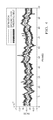
- FIG. 4 is an illustration of a yaw angle derived from ground-truth data and a yaw angle estimated from the captured images
- FIG. 5 is a schematic representation of an image with optical flow vectors computed for this image.
- FIG. 6 is a schematic representation of the functions of the device for confidence measurement for ego-motion estimation and filtering of ego-motion using the estimated confidence.
- FIG. 1 illustrates a system 1 that allows confidence measurement for ego-motion estimation and filtering of ego-motion using the estimated confidence.
- the system 1 includes a device 2 , a camera 3 and a velocity sensor 4 .
- the camera 3 is mounted on a vehicle and captures images, for example, of the area in front of the vehicle.
- the velocity sensor 4 measures the velocity of the vehicle.
- the camera 3 and the velocity sensor 4 provide the device 2 with the captured images and the measured velocity data, respectively.
- the device 2 uses the captured images and the measured velocity data in order to estimate and output data regarding orientation and motion of the camera 3 .
- the device 2 may include a processor and employs the algorithms explained in the following.
- the homography between two images captured by the camera 3 includes information about the camera's roll and pitch angle relative to the road surface 5 .
- the used coordinate system is defined in FIGS. 2 and 3 , which show side and rear views of the camera 3 , respectively.
- the coordinate system is fixed to the camera 3 and has orthogonal coordinates x, y and z.
- FIG. 2 shows the y-z-plane of the coordinate system where a pitch angle ⁇ is defined as the angle between the projection of the normal vector n onto the y-z-plane and the y-axis.
- FIG. 3 shows the x-y-plane of the coordinate system where a roll angle ⁇ is defined as the angle between the projection of the normal vector n onto the x-y-plane and the y-axis.
- a yaw angle ⁇ may be defined in the x-z-plane that is not illustrated in FIGS. 2 and 3 .
- a homography matrix H is defined as follows in Eq. 1
- H K ⁇ ( R - tn T d ) ⁇ K - 1 , Eq . ⁇ 1 and includes the intrinsic camera calibration matrix K, the distance d between the origin of the coordinate system of the camera 3 and the road surface 5 , and the relative rotation R and translation t between the two camera positions.
- the camera 3 captures consecutive images while the vehicle moves.
- Optical flow vectors are computed from an equally distributed feature grid overlaying the images.
- An optical flow vector linearly connects two points in two subsequently captured images which represent the same object in the world. For example, the camera 3 captures a first image and, subsequently after the time ⁇ t, the camera 3 captures a second image. A first point from the first image and a second point from the second image are selected, wherein the first and second points represent the same object. The optical flow vector then connects the first point and the second point. For each image captured by the camera 3 such optical flow vectors are computed for each grid point.
- the optical flow vectors are used for real-time ego-motion estimation that estimates rotational and translational parameters.
- ego-motion estimation provides a relative yaw angle ⁇ , a relative pitch angle ⁇ and a relative roll angle ⁇ as well as translational parameters, for example (T x , T y , 1) or (T x ⁇ v ⁇ t, T y ⁇ v ⁇ t, v ⁇ t)/ ⁇ (T x , T y , 1) ⁇ 2 if the vehicle's velocity v and the time ⁇ t between two image captures are known, between two camera positions.
- ground-truth In order to generate a confidence signal, a signal definition is needed defining when a signal is correct or not.
- the definition can be made with the help of ground-truth.
- the ground truth can be obtained via approaches which promise more accurate parameter estimation, but in general need a lot of computation time, e.g. bundle adjustment, or by using an IMU (inertial measurement unit) sensor to create ground-truth, e.g. a 9-axis sensor.
- IMU intial measurement unit
- ground-truth data may be computed from the images captured during training mode by bundle adjustment. A sensor for accurately measuring ground-truth data is not necessary.
- Ground-truth data for determining the pitch angle ⁇ and the roll angle ⁇ are recorded in a different way.
- the camera orientation is accurately determined when the vehicle does not move.
- This camera orientation determination can be done by any static extrinsic camera calibration method which provides the pitch angle ⁇ and the roll angle ⁇ .
- the orientation of the camera 3 to the road surface 5 is assumed to be similar to the calibrated ground truth in a certain accuracy range.
- a training mode or offline mode consecutive training images are captured by the camera 3 while the vehicle is moving and ground-truth data are recorded for the training images.
- a first output signal is estimated.
- the first output signal indicates the pitch and roll angles of the camera orientation.
- the first output signals are estimated from the images captured by the camera 3 . Since the ground-truth data provide the correct pitch and roll angles, every first output signal can be classified either as a correct signal or a false signal. The classification of the first output signals depends on how good the first output signal for the respective training image fits to the ground-truth data.
- FIG. 4 shows an example of the measurements and estimations carried out in the training mode for 100 frames/images.
- FIG. 4 illustrates the yaw angle derived from ground-truth data and the yaw angle estimated from the captured images for each frame.
- a threshold belt is defined with a pre-determined, constant distance from the ground-truth data to avoid unsecure data at the boundaries of the threshold.
- the threshold belt has two branches, one below and one above the ground-truth data. Both branches have a pre-determined, constant width and a pre-determined, constant distance from the ground-truth data. In the same manner the pitch and roll angles estimated from the images can be compared to threshold belts for the pitch and roll angles derived from ground-truth data.
- the first output signal is classified for each frame/image by separating the first output signals into two classes consisting of true positives and true negatives. In case at least one of the estimated yaw, pitch and roll angles for a given frame lies outside the respective threshold belt or inside the width of one of the two branches of the threshold belt, the first output signal of the respective image is classified as true negative. Only if all estimated yaw, pitch and roll angles for a given frame lie between the two branches of the respective threshold belt and do not touch the branches of the threshold belt, the first output signal of the respective image is classified as true positive.
- a clear definition of a correct signal and a false signal could be established on a training set.
- the definition is generalized for unknown data during runtime.
- a novel classification method is created to identify whether the outputs from the camera based motion sensor are correct or not.
- a feature set is created, which makes use of the data which is generated from the visual odometry sensor anyway.
- the feature set created for confidence measurement may consist of optical flow field properties that are determined for each of the training images.
- Optical flow vectors are computed for every point in the grid and the computational errors, in particular the epipolar errors, are estimated for every optical flow vector.
- the estimated errors of the optical flow vectors are written in a histogram.
- a non-negative set of thresholds S is defined.
- the thresholds S define the bins of the histogram. Each bin of the histogram indicates the number of the optical flow vectors in the respective image that have an error which is within the range associated with the respective bin.
- E(x, x′, ⁇ , T) we evaluate the objective E(x, x′, ⁇ , T) from which we already computed the ego-motion and choose the minimum threshold such that E or ⁇ E (if E is negative) is smaller than S.
- FIG. 5 schematically shows an image captured by the camera 3 with a grid overlaying the image.
- FIG. 5 also shows the optical flow vectors computed for this image at the grid points.
- the estimation error has been calculated for every optical flow vectors.
- the optical flow vectors having a lighter color are inliers of a particular bin of the histogram, i.e., the estimation error calculated for these optical flow vectors is smaller than the threshold S associated with the particular bin.
- the optical flow vectors having a darker color are outliers of the bin.
- the feature set may comprise orientation histograms of angles between the reprojection of the feature points from frame i to frame i+1 using the current ego-motion and the appropriate feature points in image i+1 (pyramidal).
- the histogram of inliers can further been refined using a region based evaluation of the objective, i.e. a localized histogram of inliers.
- a region based evaluation of the objective i.e. a localized histogram of inliers.
- This approach can be continued for every region to get smaller regions, i.e. more levels.
- the normalization can now be different and computed either region based (number of features in the region) or global (number of all features).
- optical flow field properties in particular the histograms, derived from each image can be classified in the same manner.
- the optical flow field properties of each training image are classified as either true positive or true negative in accordance with the classification of the respective first output signal.
- the optical flow field properties determined for a respective training image can be represented by a point in a multidimensional space.
- a separation function is generated that separates the optical flow field properties into two classes, i.e. true positives and true negatives, based on the classification of the first output signal.
- a neural network or a linear SVM (support vector machine) or an SVM with radial basis function kernel is trained. It shall be noted that any other learning algorithm could be also used to generate the separation function.
- the separation function that has been generated in the training mode allows to assess the accuracy of the estimated camera orientation parameters during runtime.
- another camera and another vehicle may be used compared to the training mode, wherein the camera and the vehicle used during runtime are identically constructed as the camera and the vehicle, respectively, used in the training mode.
- the camera 3 captures consecutive images while the vehicle is moving and, for each of the images, the same sort of optical flow field properties are derived from the images as in the training mode.
- an optical flow vector is computed for each grid point of the grid overlaying the respective image.
- the computational errors of the optical flow vectors are estimated for every optical flow vector.
- the optical flow vectors are written in a histogram, wherein the thresholds S defining the bins of the histogram are identical to the thresholds S used in the training mode. If the optical flow field properties determined in the training mode comprise further features, e.g., orientation histograms of the direction/angles of the error between the reprojection of the feature points from frame i to frame i+1 and the related feature point in frame i+1 the same sort of features are also determined during runtime.
- the optical flow field properties are represented by a point in a multidimensional space.
- optical flow field properties determined during runtime are divided into two classes, true positives and true negatives, by using the separation function generated in the training mode.
- a confidence signal can be generated for each image captured during runtime indicating whether the optical flow field properties determined for the respective image belong to the class of true positives or the class of true negatives.
- a second output signal is estimated for each of the images based on the captured images.
- the second output signal indicates an orientation of the camera and/or a change thereof, for example, the second output signal can include ego-motion estimates.
- the confidence signal is used to assess the accuracy of the second output signal.
- the device 2 smoothes the second output signals. As the output changes using this filter, the confidence also has to be propagated.
- the confidence signal is used here to decide whether the respective second output signal can be used for subsequent filtering and the confidence belt used in the definition also gives information about the accuracy of the second output signal. For example, only true positives are used for filtering and all true negatives are discarded.
- the accuracy can be used for the filter as measurement covariance information, which is required from a Kalman filter.
- a new confidence signal for the filter output can be generated from the confidence and signal inputs by evaluating the filter estimate covariance, e.g. by checking the determinant of the filter covariance in Eq. 2
- index i describes the i-th filter, as parameters of the ego-motion could be filtered separately.
- k ⁇ 1 i is defined by the filter covariance.
- ⁇ i is determined using the ⁇ -squared distribution and n i is a normalization factor given by the normal distribution.
- FIG. 6 schematically summarizes the functions of the device 2 for confidence computation for ego-motion estimation and filtering of ego-motion using the estimated confidence.
- ego-motion confidence a calculation of confidence for camera orientation estimation, e.g., the pitch and roll angles of the camera relative to the road surface, is possible as well.
- different or additional properties may be selected. Possible properties are ego-motion confidence, count of homography inliers, ratio of homography inliers to ego-motion inliers, position of centroid of the road plane inliers distribution and real world curve radius derived from yaw rate and vehicle velocity. All or a selection of the aforementioned properties may be used to derive the separation function.
- the orientation of the camera 3 to the road surface 5 can be described by the homography matrix H given above by Eq. 1.
- Optical flow vectors serve as input data to estimate the pitch and roll angles by means of the homography matrix H.
- Count of homography inliers is the number of the optical flow vectors that fit to the estimation of the homography matrix H.
- Optical flow vectors that fit to the estimated homography matrix H within pre-determined error margins are inliers.
- the position of centroid of the road plane inliers distribution can indicate a shift of the centroid of the road plane inliers relative to the center of the images.
- Ground truth data for classifier training can be obtained by any static extrinsic camera calibration method.
- the trained classifier is able to assess the accuracy of the estimated camera orientation angles.
- estimated camera orientation angles which overshoot a certain threshold corridor (difference between estimation and ground truth) get a low confidence
- camera orientation angles inside this threshold corridor get a high confidence.
- This method we are able to determine if the orientation angle estimation for the current frame/image is useful/reliable or not.
- This confidence can also be used to improve online extrinsic camera calibration algorithms by removing frames with low confidence from the angle smoothing (over time) process.
Landscapes
- Engineering & Computer Science (AREA)
- Theoretical Computer Science (AREA)
- Physics & Mathematics (AREA)
- General Physics & Mathematics (AREA)
- Computer Vision & Pattern Recognition (AREA)
- Multimedia (AREA)
- Data Mining & Analysis (AREA)
- General Engineering & Computer Science (AREA)
- Artificial Intelligence (AREA)
- Evolutionary Computation (AREA)
- Bioinformatics & Computational Biology (AREA)
- Evolutionary Biology (AREA)
- Bioinformatics & Cheminformatics (AREA)
- Life Sciences & Earth Sciences (AREA)
- Software Systems (AREA)
- Medical Informatics (AREA)
- Computing Systems (AREA)
- Mathematical Physics (AREA)
- Image Analysis (AREA)
- Image Processing (AREA)
- Traffic Control Systems (AREA)
Abstract
Description
and includes the intrinsic camera calibration matrix K, the distance d between the origin of the coordinate system of the
which show oversampling for every feature vector xi.
Claims (25)
Applications Claiming Priority (3)
| Application Number | Priority Date | Filing Date | Title |
|---|---|---|---|
| EP16162369.9 | 2016-03-24 | ||
| EP16162369 | 2016-03-24 | ||
| EP16162369.9A EP3223196B1 (en) | 2016-03-24 | 2016-03-24 | A method and a device for generating a confidence measure for an estimation derived from images captured by a camera mounted on a vehicle |
Publications (2)
| Publication Number | Publication Date |
|---|---|
| US20170278014A1 US20170278014A1 (en) | 2017-09-28 |
| US10452999B2 true US10452999B2 (en) | 2019-10-22 |
Family
ID=55646358
Family Applications (1)
| Application Number | Title | Priority Date | Filing Date |
|---|---|---|---|
| US15/467,684 Active 2037-11-22 US10452999B2 (en) | 2016-03-24 | 2017-03-23 | Method and a device for generating a confidence measure for an estimation derived from images captured by a camera mounted on a vehicle |
Country Status (3)
| Country | Link |
|---|---|
| US (1) | US10452999B2 (en) |
| EP (1) | EP3223196B1 (en) |
| CN (1) | CN107230218B (en) |
Families Citing this family (26)
| Publication number | Priority date | Publication date | Assignee | Title |
|---|---|---|---|---|
| US9798322B2 (en) | 2014-06-19 | 2017-10-24 | Skydio, Inc. | Virtual camera interface and other user interaction paradigms for a flying digital assistant |
| US12007763B2 (en) | 2014-06-19 | 2024-06-11 | Skydio, Inc. | Magic wand interface and other user interaction paradigms for a flying digital assistant |
| US9678506B2 (en) | 2014-06-19 | 2017-06-13 | Skydio, Inc. | Magic wand interface and other user interaction paradigms for a flying digital assistant |
| US10520943B2 (en) | 2016-08-12 | 2019-12-31 | Skydio, Inc. | Unmanned aerial image capture platform |
| WO2018051492A1 (en) * | 2016-09-16 | 2018-03-22 | 三菱電機株式会社 | Optical flow accuracy calculating device and optical flow accuracy calculating method |
| US11295458B2 (en) | 2016-12-01 | 2022-04-05 | Skydio, Inc. | Object tracking by an unmanned aerial vehicle using visual sensors |
| US10755419B2 (en) * | 2017-01-30 | 2020-08-25 | Nec Corporation | Moving object detection apparatus, moving object detection method and program |
| US20180293735A1 (en) * | 2017-04-11 | 2018-10-11 | Sony Corporation | Optical flow and sensor input based background subtraction in video content |
| US11144786B2 (en) * | 2017-11-02 | 2021-10-12 | Canon Kabushiki Kaisha | Information processing apparatus, method for controlling information processing apparatus, and storage medium |
| EP3746744B1 (en) * | 2018-03-07 | 2025-08-13 | Google LLC | Methods and systems for determining geographic orientation based on imagery |
| DE102018205879A1 (en) * | 2018-04-18 | 2019-10-24 | Volkswagen Aktiengesellschaft | Method, apparatus and computer readable storage medium with instructions for processing sensor data |
| US11077795B2 (en) * | 2018-11-26 | 2021-08-03 | Ford Global Technologies, Llc | Trailer angle detection using end-to-end learning |
| US11327155B2 (en) | 2018-12-21 | 2022-05-10 | Robert Bosch Gmbh | Radar sensor misalignment detection for a vehicle |
| CN111627051B (en) * | 2019-02-27 | 2023-12-15 | 中强光电股份有限公司 | Electronic device and method for estimating optical flow |
| US20200361452A1 (en) * | 2019-05-13 | 2020-11-19 | Toyota Research Institute, Inc. | Vehicles and methods for performing tasks based on confidence in accuracy of module output |
| US11663860B2 (en) * | 2019-10-25 | 2023-05-30 | Toyota Research Institute, Inc. | Dynamic and variable learning by determining and using most-trustworthy inputs |
| US11100344B2 (en) * | 2019-11-21 | 2021-08-24 | GM Global Technology Operations LLC | Image-based three-dimensional lane detection |
| US11427193B2 (en) | 2020-01-22 | 2022-08-30 | Nodar Inc. | Methods and systems for providing depth maps with confidence estimates |
| KR102550678B1 (en) | 2020-01-22 | 2023-07-04 | 노다르 인크. | Non-Rigid Stereo Vision Camera System |
| KR102890132B1 (en) * | 2020-02-04 | 2025-11-21 | 삼성전자 주식회사 | Apparatus and method for estimating road geometry |
| CN112902966A (en) * | 2021-01-28 | 2021-06-04 | 开放智能机器(上海)有限公司 | Fusion positioning system and method |
| CN113033479B (en) * | 2021-04-20 | 2024-04-26 | 超级视线科技有限公司 | Berth event identification method and system based on multilayer perception |
| CN113962846B (en) * | 2021-09-09 | 2025-09-16 | 原力图新(重庆)科技有限公司 | Image alignment method and device, computer readable storage medium and electronic equipment |
| US11577748B1 (en) | 2021-10-08 | 2023-02-14 | Nodar Inc. | Real-time perception system for small objects at long range for autonomous vehicles |
| WO2023244252A1 (en) | 2022-06-14 | 2023-12-21 | Nodar Inc. | 3d vision system with automatically calibrated stereo vision sensors and lidar sensor |
| US12482128B2 (en) * | 2022-08-17 | 2025-11-25 | Gm Cruise Holdings Llc | Identifying stability of an object based on surface normal vectors |
Citations (1)
| Publication number | Priority date | Publication date | Assignee | Title |
|---|---|---|---|---|
| US20150036888A1 (en) * | 2013-07-31 | 2015-02-05 | Trimble Navigation Ltd. | Sequential rolling bundle adjustment |
Family Cites Families (3)
| Publication number | Priority date | Publication date | Assignee | Title |
|---|---|---|---|---|
| CN103268495B (en) * | 2013-05-31 | 2016-08-17 | 公安部第三研究所 | Human body behavior modeling recognition methods based on priori knowledge cluster in computer system |
| CN104463232A (en) * | 2014-12-30 | 2015-03-25 | 中山大学 | Density crowd counting method based on HOG characteristic and color histogram characteristic |
| CN105389567B (en) * | 2015-11-16 | 2019-01-25 | 上海交通大学 | Group Anomaly Detection Method Based on Dense Optical Flow Histogram |
-
2016
- 2016-03-24 EP EP16162369.9A patent/EP3223196B1/en active Active
-
2017
- 2017-03-23 US US15/467,684 patent/US10452999B2/en active Active
- 2017-03-23 CN CN201710303642.2A patent/CN107230218B/en active Active
Patent Citations (1)
| Publication number | Priority date | Publication date | Assignee | Title |
|---|---|---|---|---|
| US20150036888A1 (en) * | 2013-07-31 | 2015-02-05 | Trimble Navigation Ltd. | Sequential rolling bundle adjustment |
Non-Patent Citations (7)
| Title |
|---|
| Bjorn Andres, et al.: "On Errors-In-Variables Regression With Arbitrary Covariance and Its Application to Optical Flow Estimation", Jun. 23, 2008, pp. 1-6. |
| Claudia Kondermann, et al.: "An Adaptive Confidence Measure for Optical Flows Based on Linear Subspace Projections", Sep. 12, 2007, pp. 132-141. |
| Geiger, Andreas, Philip Lenz, and Raquel Urtasun. "Are we ready for autonomous driving? the kitti vision benchmark suite." In Computer Vision and Pattern Recognition (CVPR), 2012 IEEE Conference on, pp. 3354-3361. IEEE, 2012. (Year: 2012). * |
| Martinez F, Manzanera A, Romero E. A motion descriptor based on statistics of optical flow orientations for action classification in video-surveillance. InMultimedia and Signal Processing 2012 (pp. 267-274). Springer, Berlin, Heidelberg. (Year: 2012). * |
| Oisin Mac Adoha, et al: "Learning a Confidence Measure for Optical Flow", vol. 3, No. 1, May 1, 2013, pp. 1107-1120. |
| Ralf Haeusler, et al.: "Ensemble Learning for Confidence Measures in Stereo Vision", 2013 IEEE Conference on Computer Vision and Pattern Recognition, Jun. 23, 2013, pp. 305-312. |
| Roberts, R., Potthast, C. and Dellaert, F., Jun. 2009. Learning general optical flow subspaces for egomotion estimation and detection of motion anomalies. In Computer Vision and Pattern Recognition, 2009. CVPR 2009. IEEE Conference on (pp. 57-64). IEEE. (Year: 2009). * |
Also Published As
| Publication number | Publication date |
|---|---|
| CN107230218A (en) | 2017-10-03 |
| EP3223196A1 (en) | 2017-09-27 |
| US20170278014A1 (en) | 2017-09-28 |
| EP3223196B1 (en) | 2021-05-05 |
| CN107230218B (en) | 2020-12-01 |
Similar Documents
| Publication | Publication Date | Title |
|---|---|---|
| US10452999B2 (en) | Method and a device for generating a confidence measure for an estimation derived from images captured by a camera mounted on a vehicle | |
| US9405982B2 (en) | Driver gaze detection system | |
| US10867189B2 (en) | Systems and methods for lane-marker detection | |
| CN104573646B (en) | Chinese herbaceous peony pedestrian detection method and system based on laser radar and binocular camera | |
| US10187617B2 (en) | Automatic detection of moving object by using stereo vision technique | |
| CN111191629A (en) | Multi-target-based image visibility detection method | |
| CN102087703A (en) | Method for determining frontal face pose | |
| CN104899590A (en) | Visual target tracking method and system for unmanned aerial vehicle | |
| CN105976402A (en) | Real scale obtaining method of monocular vision odometer | |
| CN111274862B (en) | Device and method for generating a tag object of a vehicle's surroundings | |
| Li et al. | Rotating box multi-objective visual tracking algorithm for vibration displacement measurement of large-span flexible bridges | |
| CN108645375B (en) | Rapid vehicle distance measurement optimization method for vehicle-mounted binocular system | |
| US11488391B2 (en) | Method and apparatus for estimating position | |
| US11080562B1 (en) | Key point recognition with uncertainty measurement | |
| US20230206600A1 (en) | Information processing system, information processing device, non-transitory computer-readable medium, and information processing method | |
| US20180204333A1 (en) | Object detection device and object detection method | |
| Bartl et al. | Planecalib: Automatic camera calibration by multiple observations of rigid objects on plane | |
| CN118990480B (en) | A humanoid robot target recognition and positioning method and system | |
| CN120808296B (en) | Target detection methods, devices, equipment, and storage media based on multimodal fusion | |
| CN105303554A (en) | Image feature point 3D reconstruction method and device | |
| KR102831462B1 (en) | Apparatus for detecting object of vehicle and method thereof | |
| Zeisler et al. | Vision based lane change detection using true flow features | |
| CN113221739A (en) | Monocular vision-based vehicle distance measuring method | |
| CN118314179A (en) | Error-time-actual detection method, device and equipment on AI binocular stitching camera | |
| CN115984321A (en) | Velocity measurement method, device, equipment and storage medium |
Legal Events
| Date | Code | Title | Description |
|---|---|---|---|
| AS | Assignment |
Owner name: DELPHI TECHNOLOGIES, INC., MICHIGAN Free format text: ASSIGNMENT OF ASSIGNORS INTEREST;ASSIGNORS:LESSMANN, STEPHANIE;MEUTER, MIRKO;WESTERHOFF, JENS;REEL/FRAME:041707/0927 Effective date: 20170320 |
|
| AS | Assignment |
Owner name: APTIV TECHNOLOGIES LIMITED, BARBADOS Free format text: ASSIGNMENT OF ASSIGNORS INTEREST;ASSIGNOR:DELPHI TECHNOLOGIES INC.;REEL/FRAME:047153/0902 Effective date: 20180101 |
|
| STPP | Information on status: patent application and granting procedure in general |
Free format text: NON FINAL ACTION MAILED |
|
| STPP | Information on status: patent application and granting procedure in general |
Free format text: RESPONSE TO NON-FINAL OFFICE ACTION ENTERED AND FORWARDED TO EXAMINER |
|
| STPP | Information on status: patent application and granting procedure in general |
Free format text: NOTICE OF ALLOWANCE MAILED -- APPLICATION RECEIVED IN OFFICE OF PUBLICATIONS |
|
| STPP | Information on status: patent application and granting procedure in general |
Free format text: PUBLICATIONS -- ISSUE FEE PAYMENT VERIFIED |
|
| STCF | Information on status: patent grant |
Free format text: PATENTED CASE |
|
| MAFP | Maintenance fee payment |
Free format text: PAYMENT OF MAINTENANCE FEE, 4TH YEAR, LARGE ENTITY (ORIGINAL EVENT CODE: M1551); ENTITY STATUS OF PATENT OWNER: LARGE ENTITY Year of fee payment: 4 |
|
| AS | Assignment |
Owner name: APTIV TECHNOLOGIES (2) S.A R.L., LUXEMBOURG Free format text: ENTITY CONVERSION;ASSIGNOR:APTIV TECHNOLOGIES LIMITED;REEL/FRAME:066746/0001 Effective date: 20230818 Owner name: APTIV MANUFACTURING MANAGEMENT SERVICES S.A R.L., LUXEMBOURG Free format text: MERGER;ASSIGNOR:APTIV TECHNOLOGIES (2) S.A R.L.;REEL/FRAME:066566/0173 Effective date: 20231005 Owner name: APTIV TECHNOLOGIES AG, SWITZERLAND Free format text: ASSIGNMENT OF ASSIGNORS INTEREST;ASSIGNOR:APTIV MANUFACTURING MANAGEMENT SERVICES S.A R.L.;REEL/FRAME:066551/0219 Effective date: 20231006 Owner name: APTIV TECHNOLOGIES AG, SWITZERLAND Free format text: ASSIGNMENT OF ASSIGNOR'S INTEREST;ASSIGNOR:APTIV MANUFACTURING MANAGEMENT SERVICES S.A R.L.;REEL/FRAME:066551/0219 Effective date: 20231006 |